Q-in-Qを使用した静的VXLANトンネル
小規模な MC-LAG ネットワークでは、静的 VXLAN を使用して、ネットワーク内のコントロールプレーンの複雑さを軽減できます。静的 VXLAN で VTEP を設定するのは簡単です。この例を使用して、データセンター間にQ-in-Qタグ(VLAN変換)を使用した静的VXLANトンネルを設定します。この例では、次の機能に焦点を当てます。
-
静的 VXLAN—静的 VXLAN は、レイヤー 2 パス(トンネル)を作成することで、異なるデータ センターのサーバーを接続します。静的 VXLAN の詳細については、静的 VXLAN を参照してください。
-
Q-in-Qトンネル—Q-in-Qトンネルは、異なる顧客VLAN(C-VLAN)トラフィックを単一のサービスプロバイダVLANに分離してバンドルします。
Q-in-Qトンネルの詳細については、 Q-in-Qトンネリングの設定とVLAN Q-in-QトンネリングとVLAN変換を参照してください。
-
MC-LAG—MC LAGは、冗長性とロードバランシングを提供します。2つのピアデバイス間のICLおよびICCP接続を設定して、MC-LAGを作成します。MC-LAGの詳細については、「マルチシャーシリンクアグリゲーショングループを理解する」を参照してください
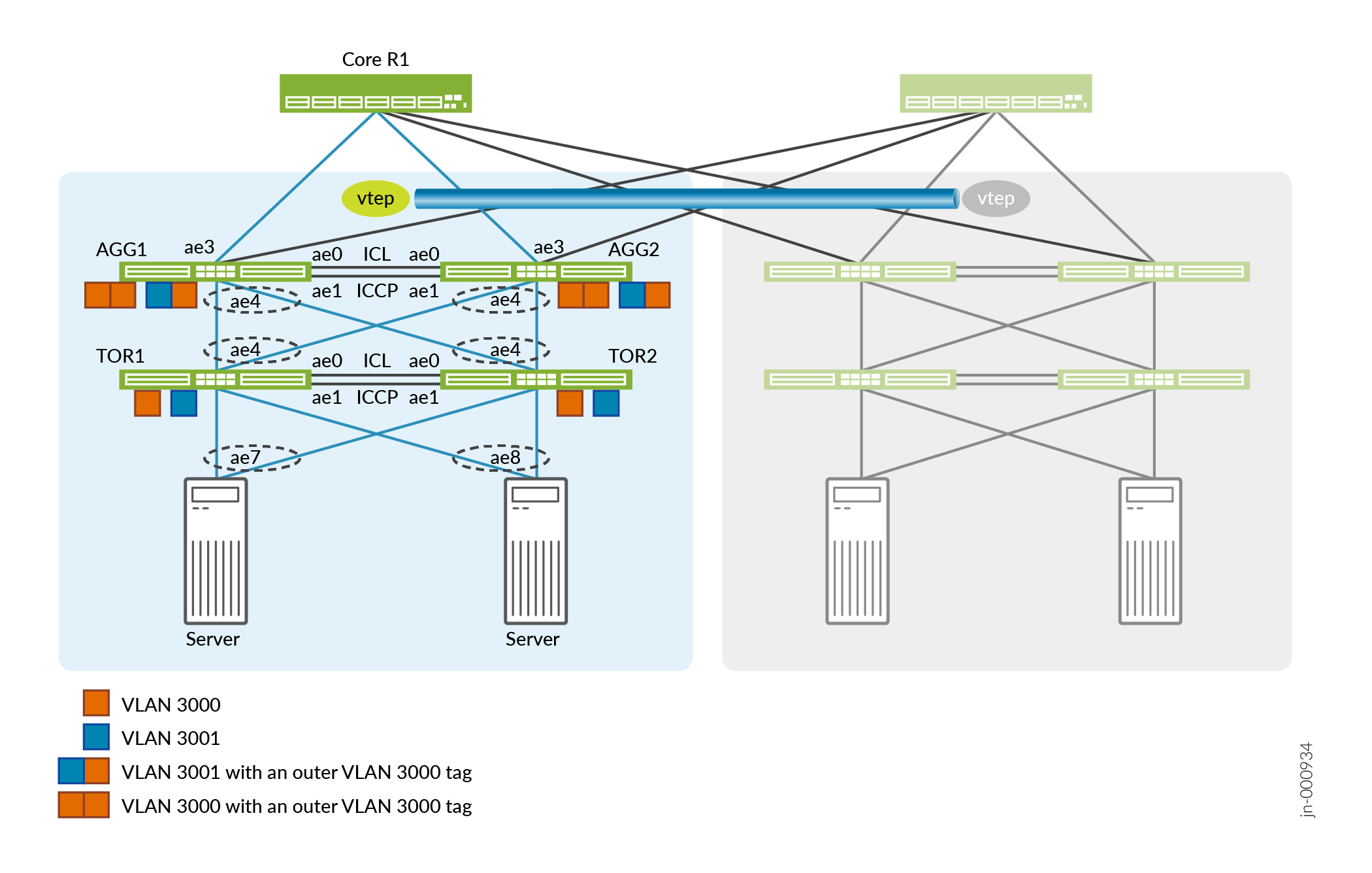
図1 は、スパインリーフデータセンター(POD)の一部を示しています。POD内では、TORデバイス(TOR1およびTOR2)が以下のサーバーからVLANを収集し、VLAN変換(Q-in-Qトンネル)も管理します。アグリゲータは、さまざまなTORデバイスからVLANを収集し、PODのゲートウェイとして機能します。2つのPOD間のゲートウェイとして、静的なVXLANトンネルを使用します。ピア TOR デバイスとピア アグリゲーターの間で MC-LAG を設定します。リファレンステスト環境では、64個のポッドを使用した構成をテストしました。この例では、アグリゲーターと TOR デバイスを 1 つのポッドで構成する方法について説明します。
この例は、既存のIPファブリックの上に構成されています。 IPファブリックアンダーレイネットワークの設計と実装を参照してください。
アグリゲーターの設定
次のセクションでは、アグリゲーターの設定方法について説明します。
- 集合型イーサネットとMC-LAGをサポートするようにアグリゲーターを設定します。
-
集合型イーサネットインターフェイスの最大数を設定します。
-
LAGのサービス識別子(SID)を設定します。
-
ループバックアドレスを設定します。
-
管理ポートを設定します。管理インターフェイスを「常時稼働」ポートとして使用し、ICCPピア間のキープアライブ通信をサポートします。
AGG1およびAGG2
set chassis aggregated-devices ethernet device-count 64
set switch-options service-id 1
AGG1
set interfaces lo0 unit 0 family inet address 192.168.1.4/32 primary
set interfaces em0 unit 0 family inet address 10.48.49.69/221
AGG2
set interfaces lo0 unit 0 family inet address 192.168.1.5/32 primary
set nterfaces em0 unit 0 family inet address 10.48.49.117/22
-
- 集合型イーサネットインターフェイスを割り当てます。
-
ae0とae1は、アグリゲーター間のICLおよびICCPリンクを形成します。
-
AE3は、アグリゲータをスパインデバイスに接続します。
-
ae4 は、アグリゲータを TOR デバイスに接続します。
AGG1およびAGG2
set interfaces xe-0/0/49:0 ether-options 802.3ad ae0
set interfaces xe-0/0/49:1 ether-options 802.3ad ae1
set interfaces xe-0/0/48:0 ether-options 802.3ad ae3
set interfaces xe-0/0/50:0 ether-options 802.3ad ae4
set interfaces xe-0/0/50:1 ether-options 802.3ad ae4
-
- 集合型イーサネットインターフェイスでLACPを有効にします。高速周期間隔でLACPを有効にし、1秒ごとにパケットを送信します。
AGG1およびAGG2
set interfaces ae4 aggregated-ether-options minimum-links 1
set interfaces ae4 aggregated-ether-options lacp active
set interfaces ae4 aggregated-ether-options lacp periodic fast
set interfaces ae4 aggregated-ether-options lacp system-id 00:00:00:00:04:01
set interfaces ae4 aggregated-ether-options lacp admin-key 4
- アグリゲーターからTORデバイスへのMC-LAGインターフェイスを設定し、アクティブ/アクティブモードに設定します。各ピアに固有のシャーシIDを設定します。
AGG1およびAGG2
set interfaces ae4 aggregated-ether-options mc-ae mc-ae-id 4
set interfaces ae4 aggregated-ether-options mc-ae redundancy-group 1
set interfaces ae4 aggregated-ether-options mc-ae mode active-active
set interfaces ae4 aggregated-ether-options mc-ae status-control active
set interfaces ae4 aggregated-ether-options mc-ae init-delay-time 300
AGG1
set interfaces ae4 aggregated-ether-options mc-ae chassis-id 0
AGG2
set interfaces ae4 aggregated-ether-options mc-ae chassis-id 1
- ICL全体でICCPピア(AGG1およびAGG2)を設定します。キープアライブメッセージを交換するために
backup-liveness-detectionを設定するときには、管理リンクのIPアドレスを使用します。AGG1
set interfaces ae0 description "ICCP link Connected to MCLAG peer"
set interfaces ae0 unit 0 family inet address 172.16.10.1/30
set multi-chassis multi-chassis-protection 172.16.10.2 interface ae1
set protocols iccp local-ip-addr 172.16.10.1
set protocols iccp peer 172.16.10.2 session-establishment-hold-time 600
set protocols iccp peer 172.16.10.2 redundancy-group-id-list 1
set protocols iccp peer 172.16.10.2 backup-liveness-detection backup-peer-ip 10.48.49.69
set protocols iccp peer 172.16.10.2 liveness-detection minimum-interval 1000
AGG2
set interfaces ae0 description "ICCP link Connected to MCLAG peer"
set interfaces ae0 unit 0 family inet address 172.16.10.2/30
set multi-chassis multi-chassis-protection 172.16.10.1 interface ae1
set protocols iccp local-ip-addr 172.16.10.2
set protocols iccp peer 172.16.10.1 session-establishment-hold-time 600
set protocols iccp peer 172.16.10.1 redundancy-group-id-list 1
set protocols iccp peer 172.16.10.1 backup-liveness-detection backup-peer-ip 10.48.49.117
set protocols iccp peer 172.16.10.1 liveness-detection minimum-interval 1000
- VLAN をサポートするようにインターフェイスを設定します。
AGG1およびAGG2
set vlans SP-VLAN-3000 vlan-id 3000
set vlans SP-VLAN-3000 interface ae1.3000
set vlans SP-VLAN-3000 interface ae4.3000
set vlans SP-VLAN-3001 vlan-id 3001
set vlans SP-VLAN-3001 interface ae1.3001
set vlans SP-VLAN-3001 interface ae4.3001

set interfaces ae1 unit 3000 encapsulation vlan-bridge
set interfaces ae1 unit 3000 vlan-id 3000
set interfaces ae1 unit 3001 encapsulation vlan-bridge
set interfaces ae1 unit 3001 vlan-id 3001

set interfaces ae4 description "Connected to TOR1 TOR2"
set interfaces ae4 flexible-vlan-tagging
set interfaces ae4 encapsulation flexible-ethernet-services

set interfaces ae4 unit 3000 encapsulation vlan-bridge
set interfaces ae4 unit 3000 vlan-id 3000
set interfaces ae4 unit 3001 encapsulation vlan-bridge
set interfaces ae4 unit 3001 vlan-id 3001
- スパインデバイスへのインターフェイスを設定します。
AGG1
set interfaces ae3 description "Connected to Spine-1"
set interfaces ae3 unit 0 family inet address 192.168.100.2/24
AGG2
set interfaces ae3 description "Connected to Spine-1"
set interfaces ae3 unit 0 family inet address 192.168.200.2/24
- ローカルおよびリモートの VTEP インターフェイスを設定して、静的 VXLAN を有効にします。
AGG1およびAGG2
set switch-options vtep-source-interface lo0.0
set switch-options remote-vtep-list 192.168.1.6
- VLAN をリモート VTEP にマッピングします。
AGG1およびAGG2
set vlans SP-VLAN-3000 vxlan vni 103000
set vlans SP-VLAN-3000 vxlan ingress-node-replication
set vlans SP-VLAN-3000 vxlan static-remote-vtep-list 192.168.1.6
set vlans SP-VLAN-3001 vxlan vni 103001
set vlans SP-VLAN-3001 vxlan ingress-node-replication
set vlans SP-VLAN-3001 vxlan static-remote-vtep-list 192.168.1.6
TOR デバイスの設定
次のセクションでは、TOR デバイスの設定方法について説明します。
- 集合型イーサネットとMC-LAGをサポートするようにTORデバイスを設定します。
-
集合型イーサネットインターフェイスの最大数を設定します。
-
LAGのSIDを設定します。
-
ループバックアドレスを設定します。
-
管理ポートを設定します。管理インターフェイスを「常時稼働」ポートとして使用し、ICCPピア間のキープアライブ通信をサポートします。
TOR1およびTOR2
set chassis aggregated-devices ethernet device-count 64
set switch-options service-id 1
TOR1
set interfaces lo0 unit 0 family inet address 192.168.1.8/32 primary
set interfaces em0 unit 0 family inet address 10.48.49.197/22
TOR2
set interfaces lo0 unit 0 family inet address 192.168.1.9/32 primary
set interfaces em0 unit 0 family inet address 10.48.49.196/22
-
- 集合型イーサネットインターフェイスを割り当てます。
-
ae0 と ae1 は、TOR デバイス間の ICL および ICCP リンクを形成します。
-
ae4 は、TOR デバイスをアグリゲーターに接続します。
-
ae7 と ae8 は、TOR デバイスをサーバーに接続します。
TOR1およびTOR2
set interfaces xe-0/0/0:0 ether-options 802.3ad ae0
set interfaces xe-0/0/0:1 ether-options 802.3ad ae0
set interfaces xe-0/0/0:2 ether-options 802.3ad ae1
set interfaces xe-0/0/0:3 ether-options 802.3ad ae1
set interfaces xe-0/0/1:0 ether-options 802.3ad ae4
set interfaces xe-0/0/1:1 ether-options 802.3ad ae4
set interfaces xe-0/0/2:1 ether-options 802.3ad ae7
set interfaces xe-0/0/2:3 ether-options 802.3ad ae8
-
- 集合型イーサネットインターフェイスでLACPを有効にします。速い周期間隔で LACP を有効にし、1 秒ごとにパケットを送信します。
TOR1およびTOR2
set interfaces ae4 aggregated-ether-options minimum-links 1
set interfaces ae4 aggregated-ether-options lacp active
set interfaces ae4 aggregated-ether-options lacp periodic fast
set interfaces ae4 aggregated-ether-options lacp system-id 00:00:00:00:04:02
set interfaces ae4 aggregated-ether-options lacp admin-key 4

set interfaces ae7 aggregated-ether-options minimum-links 1
set interfaces ae7 aggregated-ether-options lacp active
set interfaces ae7 aggregated-ether-options lacp periodic fast
set interfaces ae7 aggregated-ether-options lacp system-id 00:00:00:00:07:01
set interfaces ae7 aggregated-ether-options lacp admin-key 7

set interfaces ae8 aggregated-ether-options minimum-links 1
set interfaces ae8 aggregated-ether-options lacp active
set interfaces ae8 aggregated-ether-options lacp periodic fast
set interfaces ae8 aggregated-ether-options lacp system-id 00:00:00:00:08:01
set interfaces ae8 aggregated-ether-options lacp admin-key 8
- VLANとQ-in-Q変換をサポートするようにインターフェイスを設定します。
TOR1およびTOR2
set interfaces ae1 description "ICL link Connected to MCLAG peer"
set interfaces ae1 flexible-vlan-tagging
set interfaces ae1 encapsulation encapsulation extended-vlan-bridge
set interfaces ae1 unit 3000 vlan-id 3000

set interfaces ae4 description "Connected to AGG1 AGG2"
set interfaces ae4 flexible-vlan-tagging
set interfaces ae4 encapsulation extended-vlan-bridge
set interfaces ae4 unit 3000 vlan-id-list 3000-3001
set interfaces ae4 unit 3000 input-vlan-map push
set interfaces ae4 unit 3000 output-vlan-map pop

set interfaces ae7 description "Connected to Server1"
set interfaces ae7 flexible-vlan-tagging
set interfaces ae7 encapsulation extended-vlan-bridge
set interfaces ae7 unit 3000 vlan-id-list 3000-3001
set interfaces ae7 unit 3000 input-vlan-map push
set interfaces ae7 unit 3000 output-vlan-map pop

set interfaces ae8 description "Connected to Server2"
set interfaces ae8 flexible-vlan-tagging
set interfaces ae8 encapsulation extended-vlan-bridge
set interfaces ae8 unit 3000 vlan-id-list 3000-3001
set interfaces ae8 unit 3000 input-vlan-map push
set interfaces ae8 unit 3000 output-vlan-map pop

set vlans SP-VLAN-3000 interface ae1.3000
set vlans SP-VLAN-3000 interface ae4.3000
set vlans SP-VLAN-3000 interface ae7.3000
set vlans SP-VLAN-3000 interface ae8.3000
set vlans SP-VLAN-3000 service-id 3000
set vlans SP-VLAN-3001 interface ae4.3001
set vlans SP-VLAN-3001 interface ae7.3001
set vlans SP-VLAN-3001 interface ae8.3001
set vlans SP-VLAN-3001 service-id 3001
- TORデバイスからアグリゲーターおよびサーバーにMC-LAGインターフェイスを設定し、アクティブ/アクティブモードに設定します。各ピアに固有のシャーシIDを設定します。
TOR1およびTOR2
set interfaces ae4 aggregated-ether-options mc-ae mc-ae-id 4
set interfaces ae4 aggregated-ether-options mc-ae redundancy-group 1
set interfaces ae4 aggregated-ether-options mc-ae mode active-active
set interfaces ae4 aggregated-ether-options mc-ae status-control active
set interfaces ae4 aggregated-ether-options mc-ae init-delay-time 300

set interfaces ae7 aggregated-ether-options mc-ae mc-ae-id 7
set interfaces ae7 aggregated-ether-options mc-ae redundancy-group 1
set interfaces ae7 aggregated-ether-options mc-ae mode active-active
set interfaces ae7 aggregated-ether-options mc-ae status-control active
set interfaces ae7 aggregated-ether-options mc-ae init-delay-time 300

set interfaces ae8 aggregated-ether-options mc-ae mc-ae-id 8
set interfaces ae8 aggregated-ether-options mc-ae redundancy-group 1
set interfaces ae8 aggregated-ether-options mc-ae mode active-active
set interfaces ae8 aggregated-ether-options mc-ae status-control active
set interfaces ae8 aggregated-ether-options mc-ae init-delay-time 300
TOR1
set interfaces ae4 aggregated-ether-options mc-ae chassis-id 0
set interfaces ae7 aggregated-ether-options mc-ae chassis-id 0
set interfaces ae8 aggregated-ether-options mc-ae chassis-id 0
TOR2
set interfaces ae4 aggregated-ether-options mc-ae chassis-id 1
set interfaces ae7 aggregated-ether-options mc-ae chassis-id 1
set interfaces ae8 aggregated-ether-options mc-ae chassis-id 1
- 2つのTORピア(TOR1およびTOR2)間のICL全体でICCPを設定します。キープアライブメッセージを交換するために
backup-liveness-detectionを設定するときには、管理リンクのIPアドレスを使用します。TOR1
set interfaces ae0 description "ICCP link Connected to MCLAG peer"
set interfaces ae0 unit 0 family inet address 172.16.20.1/30
set multi-chassis multi-chassis-protection 172.16.20.2 interface ae1
set protocols iccp local-ip-addr 172.16.2.1
set protocols iccp peer 172.16.20.2 session-establishment-hold-time 600
set protocols iccp peer 172.16.20.2 redundancy-group-id-list 1
set protocols iccp peer 172.16.20.2 backup-liveness-detection backup-peer-ip 10.48.49.197
set protocols iccp peer 172.16.20.2 liveness-detection minimum-interval 1000
TOR2
set interfaces ae0 description "ICCP link Connected to MCLAG peer"
set interfaces ae0 unit 0 family inet address 172.16.20.2/30
set multi-chassis multi-chassis-protection 172.16.20.1 interface ae1
set protocols iccp local-ip-addr 172.16.20.2
set protocols iccp peer 172.16.20.1 session-establishment-hold-time 600
set protocols iccp peer 172.16.20.1 redundancy-group-id-list 1
set protocols iccp peer 17.16.20.1 backup-liveness-detection backup-peer-ip 10.48.49.196
set protocols iccp peer 172.16.20.1 liveness-detection minimum-interval 1000
アグリゲーター上のQ-in-Qを使用した静的VXLANトンネルの検証
このセクションでは、静的 VXLAN トンネルを介して VLAN を管理するアグリゲータの動作を検証するVXLAN の方法について説明します。すべてのコマンドはAGG1で発行されます。
- VLAN 情報を表示します。
user@agg1> show vlans default-switch SP-VLAN-3000 NA ae1.3000* ae4.3000* vtep.32769* - マルチシャーシ集約イーサネットリンクの動作ステータスを検証します。
user@agg1> show interfaces mc-ae Member Link : ae4 Current State Machine's State: mcae active state Configuration Error Status : No Error Local Status : active Local State : up Peer Status : active Peer State : up Logical Interface : ae4.3000 Topology Type : bridge Local State : up Peer State : up Peer Ip/MCP/State : 172.16.10.2 ae1.3000 up - AGG1 と AGG2 の間の MC-LAG ステータスを確認します。
user@agg1> show iccp Redundancy Group Information for peer 172.16.10.2 TCP Connection : Established Liveliness Detection : Up Backup liveness peer status: Up Redundancy Group ID Status 1 Up Client Application: lacpd Redundancy Group IDs Joined: 1 Client Application: l2ald_iccpd_client Redundancy Group IDs Joined: 1 - 集合型イーサネットインターフェイスのLACPステータスを確認します。
user@agg1> show lacp interfaces Aggregated interface: ae4 LACP state: Role Exp Def Dist Col Syn Aggr Timeout Activity xe-0/0/50:0 Actor No No Yes Yes Yes Yes Fast Active xe-0/0/50:0 Partner No No Yes Yes Yes Yes Fast Active xe-0/0/50:1 Actor No No Yes Yes Yes Yes Fast Active xe-0/0/50:1 Partner No No Yes Yes Yes Yes Fast Active LACP protocol: Receive State Transmit State Mux State xe-0/0/50:0 Current Fast periodic Collecting distributing xe-0/0/50:1 Current Fast periodic Collecting distributing - 静的 VXLAN のローカルおよびリモート VTEP インターフェイスが動作していることを確認します。
user@agg1> show ethernet-switching vxlan-tunnel-end-point source
Logical System Name       Id  SVTEP-IP         IFL   L3-Idx    SVTEP-Mode    ELP-SVTEP-IP
<default>                 0   192.168.1.4      lo0.0    0
    L2-RTT                   Bridge Domain              VNID     Translation-VNID    MC-Group-IP    Interface
    default-switch           SP-VLAN-3000               103000                       0.0.0.0             vtep.32768


user@agg1> show ethernet-switching vxlan-tunnel-end-point remote
Logical System Name       Id  SVTEP-IP         IFL   L3-Idx    SVTEP-Mode    ELP-SVTEP-IP
<default>                 0   192.168.1.4      lo0.0    0
 RVTEP-IP         L2-RTT                   IFL-Idx   Interface    NH-Id   RVTEP-Mode  ELP-IP        Flags
 192.168.1.5      default-switch           825       vtep.32769   1784    RNVE
    VNID          MC-Group-IP
    103000        0.0.0.0
TOR デバイス上の Q-in-Q トンネルの検証
このセクションでは、TOR デバイスの 1 つで VLAN の動作を検証する方法について説明します。すべてのコマンドは TOR1 で発行されます
- VLAN 情報を表示します。
user@tor1> show vlans default-switch SP-VLAN-3000 NA ae1.3000* ae4.3000* ae7.3000* ae8.3000* - マルチシャーシ集約イーサネットリンクの動作ステータスを検証します。
user@tor1> show interfaces mc-ae Member Link : ae4 Current State Machine's State: mcae active state Configuration Error Status : No Error Local Status : active Local State : up Peer Status : active Peer State : up Logical Interface : ae4.3000 Topology Type : bridge Local State : up Peer State : up Peer Ip/MCP/State : 172.16.20.2 ae1.3000 up Member Link : ae7 Current State Machine's State: mcae active state Configuration Error Status : No Error Local Status : active Peer State : up Logical Interface : ae7.3000 Topology Type : bridge Local State : up Peer State : up Peer Ip/MCP/State : 172.16.20.2 ae1.3000 up Member Link : ae8 Current State Machine's State: mcae active state Configuration Error Status : No Error Local Status : active Local State : up Peer Status : active Peer State : up Logical Interface : ae8.3000 Topology Type : bridge Local State : up Peer State : up Peer Ip/MCP/State : 172.16.20.1 ae1.3000 up - 集合型イーサネットインターフェイスのLACPステータスを確認します。
user@tor1> show lacp interfaces Aggregated interface: ae4 LACP state: Role Exp Def Dist Col Syn Aggr Timeout Activity xe-0/0/1:0 Actor No No Yes Yes Yes Yes Fast Active xe-0/0/1:0 Partner No No Yes Yes Yes Yes Fast Active xe-0/0/1:1 Actor No No Yes Yes Yes Yes Fast Active xe-0/0/1:1 Partner No No Yes Yes Yes Yes Fast Active LACP protocol: Receive State Transmit State Mux State xe-0/0/1:0 Current Fast periodic Collecting distributing xe-0/0/1:1 Current Fast periodic Collecting distributing Aggregated interface: ae7 LACP state: Role Exp Def Dist Col Syn Aggr Timeout Activity xe-0/0/2:1 Actor No No Yes Yes Yes Yes Fast Active xe-0/0/2:1 Partner No No Yes Yes Yes Yes Fast Active LACP protocol: Receive State Transmit State Mux State xe-0/0/2:1 Current Fast periodic Collecting distributing Aggregated interface: ae8 LACP state: Role Exp Def Dist Col Syn Aggr Timeout Activity xe-0/0/2:3 Actor No No Yes Yes Yes Yes Fast Active xe-0/0/2:3 Partner No No Yes Yes Yes Yes Fast Active LACP protocol: Receive State Transmit State Mux State xe-0/0/2:3 Current Fast periodic Collecting distributing - TOR1 と TOR2 の間の MC-LAG ステータスを確認します。
user@tor1> show iccp

Redundancy Group Information for peer 172.16.20.2
  TCP Connection       : Established
  Liveliness Detection : Up
  Backup liveness peer status: Up
  Redundancy Group ID          Status
    1                           Up

Client Application: l2ald_iccpd_client
  Redundancy Group IDs Joined: 1

Client Application: lacpd
  Redundancy Group IDs Joined: 1