例:スポークルーターごとに異なるメッシュグループを使用したBGPベースのH-VPLSの設定
この例では、異なるメッシュグループを使用して階層型仮想プライベートLANサービス(H-VPLS)を設定し、H-VPLS機能を提供する方法を示し、設定を確認する手順を示します。これは、ジュニパーネットワークス実装で可能なH-VPLS設定の1つです。別のタイプの設定については、 例:単一メッシュグループを使用してレイヤー2回線を終端するLDPベースのH-VPLSの設定を参照してください。
メッシュグループを使用することで、LDPベースのVPLSコントロールプレーンの拡張性が向上し、LDPセッションのフルメッシュが不要になります。この例では、BGPベースのVPLSを使用しています。
この例は、以下のセクションにまとめられています。
要件
この例では、以下のハードウェアコンポーネントを使用しています。
ルーターPE1、ルーターPE2、ルーターPE3、ルーターPE4用の4つのMXシリーズ5Gユニバーサルルーティングプラットフォーム
ルーターCE4用M Seriesマルチサービスエッジルーター1台
デバイスCE1およびデバイスCE2用の2つのEXシリーズイーサネットスイッチ
ルーターCE3用Jシリーズサービスルーター1台
概要とトポロジー
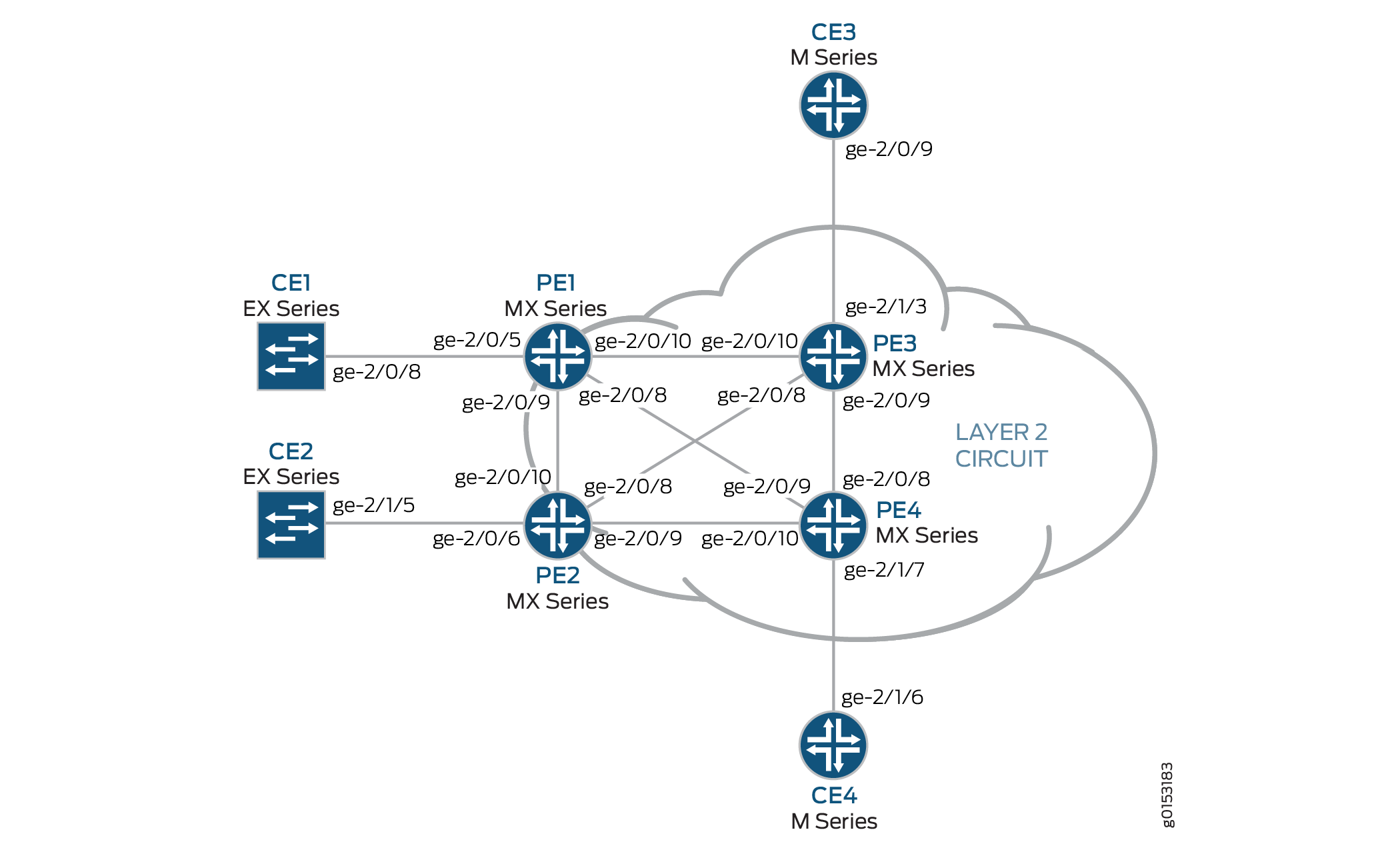
図1 は、この例で使用されている物理トポロジーを示しています。
 の物理的トポロジー
この例で使用されている基本設定を以下に説明します。
ルーターPE1とルーターPE2は、MTUデバイスとして設定されています。
ルーターPE3とルーターPE4はPE-rルーターとして設定され、それぞれLDPベースのVPLSルーティングインスタンスを使用します。
LDP および OSPF プロトコルは、すべての MTU デバイスと PE-r ルーターで設定されています。
コアに面するインターフェイスは、MPLSアドレスファミリーで有効になります。
オプションで、VPLSルーティングインスタンスは
no-tunnel-interfaceステートメントを使用してPE-rルーター上に設定できます。これにより、ルーターでラベルスイッチインターフェイス(LSI)を使用できるようになります。これは、ルーターにトンネルサービスPICがない場合や、トンネルサービスのサポートが組み込まれていない場合に便利です。すべてのルーターは、ループバックIPアドレスで設定されています。
BGPはPE-rルーターで設定されています。オプションで、ルートリフレクションを設定することもできます。これは、内部BGP(IBGP)のスケーリングに有効です。BGP設定には、BGPを使用したレイヤー2 VPNシグナリングをサポートするための
[edit protocols bgp group group-name family l2vpn]階層レベルのsignalingステートメントが含まれています。
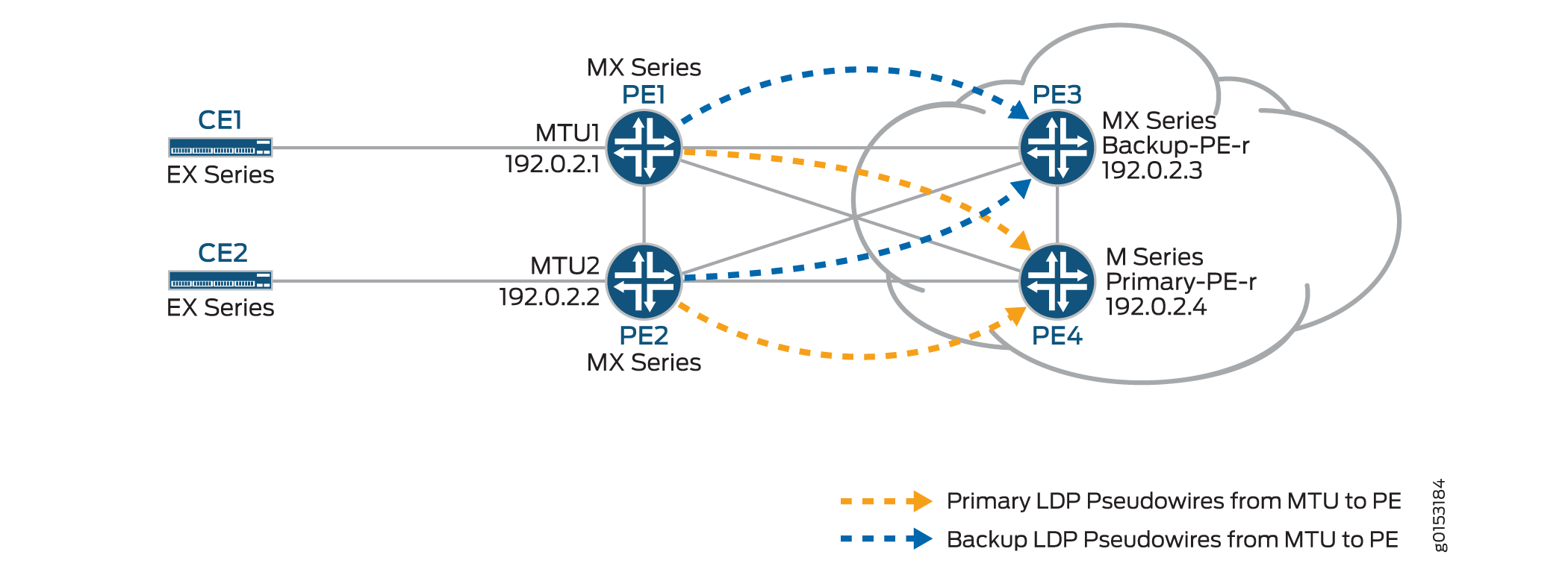
図2 は、この例で使用されている論理トポロジーを示しています。
 の論理トポロジー
図2:
MTUデバイス(ルーターPE1およびルーターPE2)は、PE-rルーター(ルーターPE3およびルーターPE4)へのレイヤー2回線接続を持っています。冗長性のために、PE-rルーターへのレイヤー2回線接続用にバックアップネイバーが設定されています。
[edit protocols]階層のl2circuitステートメントは、MTUデバイスに含まれています。VPLSルーティングインスタンスは、PE-rルーター上に設定されます。
PE-r ルーター上の VPLS ルーティング インスタンスでは、メッシュ グループが作成され、MTU デバイスから発信されるレイヤー 2 回線疑似配線を終端します。
各 MTU デバイスは、異なる仮想回線 ID で設定されます。
各PE-rルーターのメッシュグループ設定には、MTUデバイスで使用される仮想回線IDと一致するVPLS ID値が含まれています。
設定
BGPベースのVPLSを使用して、各スポークPE-rルーターに異なるメッシュグループを持つH-VPLSを設定するには、BGPを実行するには、以下のタスクを実行します。
スポーク MTU PE ルーターの設定
ステップバイステップの手順
ルーターPE1で、ルーターCE1に接続されたギガビットイーサネットインターフェイスを設定します。
encapsulationステートメントを含め、ethernet-cccオプションを指定します。また、familyステートメントを含め、cccオプションを指定することで、論理インターフェイスを設定します。[edit interfaces] ge-2/0/5 { encapsulation ethernet-ccc; unit 0 { family ccc; } }ルーターPE1では、
neighborステートメントを含め、ルーターPE3のIPアドレスをネイバーとして指定して、レイヤー2回線を設定します。ギガビットイーサネット論理インターフェイスを設定するには、virtual-circuit-idステートメントを含め、IDとして100を指定します。また、backup-neighborステートメントを含め、バックアップネイバーとしてルーターPE4のループバックインターフェイスIPアドレスを指定し、standbyステートメントを含めて、レイヤー2回線のバックアップネイバーを設定します。[edit protocols] l2circuit { neighbor 192.0.2.3 { interface ge-2/0/5.0 { virtual-circuit-id 100; backup-neighbor 192.0.2.4 { # Backup H-VPLS PE router standby; } } }ルーターPE2で、ルーターCE2に接続されたギガビットイーサネットインターフェイスを設定します。
encapsulationステートメントを含め、ethernet-cccオプションを指定します。また、familyステートメントを含め、cccオプションを指定することで、論理インターフェイスを設定します。[edit interfaces] ge-2/0/6 { encapsulation ethernet-ccc; unit 0 { family ccc; } }ルーターPE2では、
neighborステートメントを含め、ルーターPE3のIPアドレスをネイバーとして指定して、レイヤー2回線を設定します。ギガビットイーサネット論理インターフェイスを設定するには、virtual-circuit-idステートメントを含め、IDとして200を指定します。encapsulation-typeステートメントを含め、ethernetオプションを指定することで、カプセル化を設定します。また、backup-neighborステートメントを含め、ルーターPE4のループバックインターフェイスIPアドレスをバックアップネイバーとして指定し、standbyステートメントを含めて、レイヤー2回線のバックアップネイバーを設定します。[edit protocols] l2circuit { neighbor 192.0.2.3 { interface ge-1/0/2.0 { virtual-circuit-id 200; # different VC-ID encapsulation-type ethernet; # default encapsulation backup-neighbor 192.0.2.4 { standby; } } } }
ハブ PE(PE-r)の設定
ステップバイステップの手順
ルーターPE3(プライマリハブ)で、ルーターCE3に接続されたギガビットイーサネットインターフェイスを設定します。
encapsulationステートメントを含め、ethernet-vplsオプションを指定します。また、family vplsステートメントを含めて論理インターフェイスを設定します。[edit interfaces] ge-2/0/0 { encapsulation ethernet-vpls; unit 0 { family vpls; } } lo0 { unit 0 { family inet { address 192.0.2.3/24; } } }ルーターPE4(バックアップハブ)で、ルーターCE4に接続されたギガビットイーサネットインターフェイスを設定します。
encapsulationステートメントを含め、ethernet-vplsオプションを指定します。また、family vplsステートメントを含めて論理インターフェイスを設定します。[edit interfaces] ge-2/1/7 { encapsulation ethernet-vpls; unit 0 { description to_CE4; family vpls; } }lo0 { unit 0 { family inet { address 192.0.2.4/24; } } }PE-rルーターPE3では、
[edit routing-instances H-VPLS]階層レベルにinstance-typeステートメントを含め、vplsオプションを指定することで、BGPベースのVPLSルーティングインスタンスを設定します。interfaceステートメントを含め、ルーターCE3に接続されたギガビットイーサネットインターフェイスを指定します。ルート識別子を設定し、ルートアドバタイズメントが一意であることを確認するには、route-distinguisherステートメントを含め、値として192.0.2.3:33を指定します。また、VPLSに参加している他のルーターへのルートアドバタイズメントに含まれるように、VPNルーティングおよび転送(VRF)ルートターゲットを設定します。VRFルートターゲットを設定するには、vrf-targetステートメントを含め、値としてtarget:64510:2を指定します。オプションとして、LSIインターフェイスの使用を有効にするno-tunnel-servicesステートメントを含めます。これは、デバイスにトンネルサービスがない場合に便利です。この例では、no-tunnel-servicesステートメントは省略されています。オプションとして、site-rangeステートメントを含めて、疑似回線の立ち上げを許可するために受け入れ可能な最大サイト識別子の上限を指定することができます。この例では、site-rangeステートメントは省略されています。デフォルトの65,534を使用することを推奨します。各 MTU PE デバイスの VPLS プロトコルとメッシュ グループを設定します。
VPLSプロトコルを設定するには、
[edit routing-instances H-VPLS protocols]階層レベルでvplsステートメントを含めます。siteステートメントを含め、サイトの名前を指定します。interfaceステートメントを含め、デバイスCE3に接続されたギガビットイーサネットインターフェイスを指定します。VPLSインスタンスの下でメッシュグループを設定すると、レイヤー2回線がVPLSインスタンスに終了します。各メッシュグループを設定するには、
mesh-groupステートメントを含め、メッシュグループ名を指定します。この例では、メッシュグループ名は各メッシュグループに関連付けられたMTUデバイスの名前です。vpls-idステートメントを含め、 PE ルーターのスポークMTUの設定で設定された仮想回線 ID と一致する ID を指定します。また、neighborステートメントを含め、各メッシュグループに関連付けられたスポークPEルーターのIPアドレスを指定します。オプションで、VPLS接続のフルメッシュを使用していない場合は、local-switchingステートメントを含めます。local-switchingステートメントは、単一のメッシュグループを設定し、複数のレイヤー2回線疑似配線を終端する場合に便利です。この例では、local-switchingステートメントを省略しています。routing-instances { H-VPLS { instance-type vpls; interface ge-2/1/3.0; route-distinguisher 192.0.2.3:33; vrf-target target:64510:2; protocols { vpls { site pe3 { site-identifier 3; interface ge-2/1/3.0; } mesh-group pe1 { vpls-id 100; neighbor 192.0.2.1; } mesh-group pe2 { vpls-id 200; neighbor 192.0.2.2; } } } } }PE-r ルーター PE4 で、ルーター PE3 のようなルーティング インスタンスを設定します。
routing-instances { H-VPLS { instance-type vpls; interface ge-2/1/7.0; route-distinguisher 192.0.2.4:44; vrf-target target:64510:2; protocols { vpls { site pe4 { site-identifier 4; interface ge-2/1/7.0; } mesh-group pe1 { vpls-id 100; neighbor 192.0.2.1; } mesh-group pe2 { vpls-id 200; neighbor 192.0.2.2; } } } } }
H-VPLS動作の検証
ステップバイステップの手順
このセクションでは、H-VPLSが想定どおりに動作していることを検証するために使用できる運用コマンドについて説明します。
ルーターPE1とルーターPE2で、
show l2circuit connectionsコマンドを使用して、ルーターPE3へのレイヤー2回線がUpされ、ルーターPE4へのレイヤー2回線がstandbyモードになっていることを確認します。出力には、割り当てられたラベル、仮想回線ID、
ETHERNETカプセル化タイプも表示されます。user@PE1> show l2circuit connections Layer-2 Circuit Connections: Legend for connection status (St) EI -- encapsulation invalid NP -- interface h/w not present MM -- mtu mismatch Dn -- down EM -- encapsulation mismatch VC-Dn -- Virtual circuit Down CM -- control-word mismatch Up -- operational VM -- vlan id mismatch CF -- Call admission control failure OL -- no outgoing label IB -- TDM incompatible bitrate NC -- intf encaps not CCC/TCC TM -- TDM misconfiguration BK -- Backup Connection ST -- Standby Connection CB -- rcvd cell-bundle size bad SP -- Static Pseudowire LD -- local site signaled down RS -- remote site standby RD -- remote site signaled down XX -- unknown Legend for interface status Up -- operational Dn -- down Neighbor: 192.0.2.3 Interface Type St Time last up # Up trans ge-2/0/5.0(vc 100) rmt Up Oct 18 15:55:07 2012 1 Remote PE: 192.0.2.3, Negotiated control-word: No Incoming label: 299840, Outgoing label: 800001 Negotiated PW status TLV: No Local interface: ge-2/0/5.0, Status: Up, Encapsulation: ETHERNET Neighbor: 192.0.2.4 Interface Type St Time last up # Up trans ge-2/0/5.0(vc 100) rmt STuser@PE2> show l2circuit connections Layer-2 Circuit Connections: Legend for connection status (St) EI -- encapsulation invalid NP -- interface h/w not present MM -- mtu mismatch Dn -- down EM -- encapsulation mismatch VC-Dn -- Virtual circuit Down CM -- control-word mismatch Up -- operational VM -- vlan id mismatch CF -- Call admission control failure OL -- no outgoing label IB -- TDM incompatible bitrate NC -- intf encaps not CCC/TCC TM -- TDM misconfiguration BK -- Backup Connection ST -- Standby Connection CB -- rcvd cell-bundle size bad SP -- Static Pseudowire LD -- local site signaled down RS -- remote site standby RD -- remote site signaled down XX -- unknown Legend for interface status Up -- operational Dn -- down Neighbor: 192.0.2.3 Interface Type St Time last up # Up trans ge-2/0/6.0(vc 200) rmt Up Oct 18 15:55:07 2012 1 Remote PE: 192.0.2.3, Negotiated control-word: No Incoming label: 299872, Outgoing label: 800002 Negotiated PW status TLV: No Local interface: ge-2/0/6.0, Status: Up, Encapsulation: ETHERNET Neighbor: 192.0.2.4 Interface Type St Time last up # Up trans ge-2/0/6.0(vc 200) rmt STルーターPE1とルーターPE2で、
show ldp neighborコマンドを使用して、ループバックインターフェイスとプライマリおよびバックアップH-VPLSハブネイバーとの間でターゲットLDPセッションが作成されていることを確認します。user@PE1> show ldp neighbor Address Interface Label space ID Hold time 10.10.3.2 ge-2/0/9.0 192.0.2.2:0 13 10.10.1.2 ge-2/0/10.0 192.0.2.3:0 10 192.0.2.3 lo0.0 192.0.2.3:0 36 192.0.2.4 lo0.0 192.0.2.4:0 39 10.10.9.2 ge-2/0/8.0 192.0.2.4:0 14
user@PE2> show ldp neighbor Address Interface Label space ID Hold time 10.10.3.1 ge-2/0/10.0 192.0.2.1:0 12 10.10.5.2 ge-2/0/9.0 192.0.2.4:0 11 10.10.4.1 ge-2/0/8.0 192.0.2.3:0 11 192.0.2.3 lo0.0 192.0.2.3:0 39 192.0.2.4 lo0.0 192.0.2.4:0 38
ルーターPE3とルーターPE4で、
show vpls connectionsコマンドを使用して、終端されたLDPベースのVPLSとBGPベースのVPLSレイヤー2回線の両方でVPLS接続ステータスがUpされていることを確認します。user@PE3> show vpls connections Layer-2 VPN connections: Legend for connection status (St) EI -- encapsulation invalid NC -- interface encapsulation not CCC/TCC/VPLS EM -- encapsulation mismatch WE -- interface and instance encaps not same VC-Dn -- Virtual circuit down NP -- interface hardware not present CM -- control-word mismatch -> -- only outbound connection is up CN -- circuit not provisioned <- -- only inbound connection is up OR -- out of range Up -- operational OL -- no outgoing label Dn -- down LD -- local site signaled down CF -- call admission control failure RD -- remote site signaled down SC -- local and remote site ID collision LN -- local site not designated LM -- local site ID not minimum designated RN -- remote site not designated RM -- remote site ID not minimum designated XX -- unknown connection status IL -- no incoming label MM -- MTU mismatch MI -- Mesh-Group ID not available BK -- Backup connection ST -- Standby connection PF -- Profile parse failure PB -- Profile busy RS -- remote site standby SN -- Static Neighbor LB -- Local site not best-site RB -- Remote site not best-site VM -- VLAN ID mismatch Legend for interface status Up -- operational Dn -- down Instance: H-VPLS BGP-VPLS State Local site: pe3 (3) connection-site Type St Time last up # Up trans 4 rmt Up Oct 18 15:58:39 2012 1 Remote PE: 192.0.2.4, Negotiated control-word: No Incoming label: 800267, Outgoing label: 800266 Local interface: vt-2/0/9.135266562, Status: Up, Encapsulation: VPLS Description: Intf - vpls H-VPLS local site 3 remote site 4 LDP-VPLS State Mesh-group connections: pe1 Neighbor Type St Time last up # Up trans 192.0.2.1(vpls-id 100) rmt Up Oct 18 15:55:07 2012 1 Remote PE: 192.0.2.1, Negotiated control-word: No Incoming label: 800001, Outgoing label: 299840 Negotiated PW status TLV: No Local interface: vt-2/0/10.135266560, Status: Up, Encapsulation: ETHERNET Description: Intf - vpls H-VPLS neighbor 192.0.2.1 vpls-id 100 Mesh-group connections: pe2 Neighbor Type St Time last up # Up trans 192.0.2.2(vpls-id 200) rmt Up Oct 18 15:55:07 2012 1 Remote PE: 192.0.2.2, Negotiated control-word: No Incoming label: 800002, Outgoing label: 299872 Negotiated PW status TLV: No Local interface: vt-2/0/8.135266561, Status: Up, Encapsulation: ETHERNET Description: Intf - vpls H-VPLS neighbor 192.0.2.2 vpls-id 200 user@PE4> show vpls connections Layer-2 VPN connections: Legend for connection status (St) EI -- encapsulation invalid NC -- interface encapsulation not CCC/TCC/VPLS EM -- encapsulation mismatch WE -- interface and instance encaps not same VC-Dn -- Virtual circuit down NP -- interface hardware not present CM -- control-word mismatch -> -- only outbound connection is up CN -- circuit not provisioned <- -- only inbound connection is up OR -- out of range Up -- operational OL -- no outgoing label Dn -- down LD -- local site signaled down CF -- call admission control failure RD -- remote site signaled down SC -- local and remote site ID collision LN -- local site not designated LM -- local site ID not minimum designated RN -- remote site not designated RM -- remote site ID not minimum designated XX -- unknown connection status IL -- no incoming label MM -- MTU mismatch MI -- Mesh-Group ID not available BK -- Backup connection ST -- Standby connection PF -- Profile parse failure PB -- Profile busy RS -- remote site standby SN -- Static Neighbor LB -- Local site not best-site RB -- Remote site not best-site VM -- VLAN ID mismatch Legend for interface status Up -- operational Dn -- down Instance: H-VPLS BGP-VPLS State Local site: pe4 (4) connection-site Type St Time last up # Up trans 3 rmt Up Oct 18 15:58:39 2012 1 Remote PE: 192.0.2.3, Negotiated control-word: No Incoming label: 800266, Outgoing label: 800267 Local interface: vt-2/0/8.17826050, Status: Up, Encapsulation: VPLS Description: Intf - vpls H-VPLS local site 4 remote site 3 LDP-VPLS State Mesh-group connections: pe1 Neighbor Type St Time last up # Up trans 192.0.2.1(vpls-id 100) rmt Up Oct 18 15:58:39 2012 1 Remote PE: 192.0.2.1, Negotiated control-word: No Incoming label: 800002, Outgoing label: 299856 Negotiated PW status TLV: No Local interface: vt-2/0/9.17826048, Status: Up, Encapsulation: ETHERNET Description: Intf - vpls H-VPLS neighbor 192.0.2.1 vpls-id 100 Mesh-group connections: pe2 Neighbor Type St Time last up # Up trans 192.0.2.2(vpls-id 200) rmt Up Oct 18 15:58:39 2012 1 Remote PE: 192.0.2.2, Negotiated control-word: No Incoming label: 800003, Outgoing label: 299888 Negotiated PW status TLV: No Local interface: vt-2/0/10.17826049, Status: Up, Encapsulation: ETHERNET Description: Intf - vpls H-VPLS neighbor 192.0.2.2 vpls-id 200ルーターPE3とルーターPE4で、
show vpls floodコマンドを使用して、H-VPLS PEルーターが各スポークPEサイトのフラッドグループを作成していることを確認します。user@PE3> show vpls flood Name: H-VPLS CEs: 1 VEs: 3 Flood Routes: Prefix Type Owner NhType NhIndex 0x300cc/51 FLOOD_GRP_COMP_NH __ves__ comp 1376 0x300cf/51 FLOOD_GRP_COMP_NH __all_ces__ comp 744 0x300d5/51 FLOOD_GRP_COMP_NH pe1 comp 1702 0x300d3/51 FLOOD_GRP_COMP_NH pe2 comp 1544 0x30001/51 FLOOD_GRP_COMP_NH __re_flood__ comp 740
user@PE4> show vpls flood Name: H-VPLS CEs: 1 VEs: 3 Flood Routes: Prefix Type Owner NhType NhIndex 0x300d1/51 FLOOD_GRP_COMP_NH __ves__ comp 1534 0x300d0/51 FLOOD_GRP_COMP_NH __all_ces__ comp 753 0x300d6/51 FLOOD_GRP_COMP_NH pe1 comp 1378 0x300d4/51 FLOOD_GRP_COMP_NH pe2 comp 1695 0x30002/51 FLOOD_GRP_COMP_NH __re_flood__ comp 750
ルーターPE3とルーターPE4で、
show vpls mac-tableコマンドを使用して、CEデバイスのMACアドレスが学習されたことを確認します。user@PE3> show vpls mac-table MAC flags (S -static MAC, D -dynamic MAC, L -locally learned, C -Control MAC SE -Statistics enabled, NM -Non configured MAC, R -Remote PE MAC) Routing instance : H-VPLS Bridging domain : __H-VPLS__, VLAN : NA MAC MAC Logical NH RTR address flags interface Index ID 00:21:59:0f:35:32 D vt-2/0/8.135266560 00:21:59:0f:35:33 D ge-2/1/3.0 00:21:59:0f:35:d4 D vt-2/0/9.135266561 00:21:59:0f:35:d5 D vt-2/0/10.135266562user@PE4> show vpls mac-table MAC flags (S -static MAC, D -dynamic MAC, L -locally learned, C -Control MAC SE -Statistics enabled, NM -Non configured MAC, R -Remote PE MAC) Logical system : PE4 Routing instance : H-VPLS Bridging domain : __H-VPLS__, VLAN : NA MAC MAC Logical NH RTR address flags interface Index ID 00:21:59:0f:35:32 D vt-2/0/8.17826050 00:21:59:0f:35:33 D vt-2/0/9.17826050 00:21:59:0f:35:d4 D vt-2/0/10.17826050 00:21:59:0f:35:d5 D ge-2/1/7.0CEデバイスが相互にpingを実行できることを確認します。
user@CE1> ping 10.255.14.219 # ping sent from CE1 CE4 PING 10.255.14.219 (10.255.14.219): 56 data bytes 64 bytes from 10.255.14.219: icmp_seq=0 ttl=64 time=10.617 ms 64 bytes from 10.255.14.219: icmp_seq=1 ttl=64 time=9.224 ms ^C --- 10.255.14.219 ping statistics --- 2 packets transmitted, 2 packets received, 0% packet loss round-trip min/avg/max/stddev = 9.224/9.921/10.617/0.697 ms
user@CE2> ping 10.255.14.218 # ping sent from CE2 to CE3 PING 10.255.14.218 (10.255.14.218): 56 data bytes 64 bytes from 10.255.14.218: icmp_seq=0 ttl=64 time=1.151 ms 64 bytes from 10.255.14.218: icmp_seq=1 ttl=64 time=0.674 ms ^C --- 10.255.14.218 ping statistics --- 2 packets transmitted, 2 packets received, 0% packet loss round-trip min/avg/max/stddev = 0.674/0.913/1.151/0.238 ms
関連するルーティングテーブルを確認します。
user@PE1> show route table l2circuit.0 l2circuit.0: 4 destinations, 4 routes (4 active, 0 holddown, 0 hidden) + = Active Route, - = Last Active, * = Both 192.0.2.3:NoCtrlWord:5:100:Local/96 *[L2CKT/7] 00:12:16, metric2 1 > to 10.10.1.2 via ge-2/0/10.0 192.0.2.3:NoCtrlWord:5:100:Remote/96 *[LDP/9] 00:12:16 Discard 192.0.2.4:NoCtrlWord:5:100:Local/96 *[L2CKT/7] 00:12:10, metric2 1 > to 10.10.9.2 via ge-2/0/8.0 192.0.2.4:NoCtrlWord:5:100:Remote/96 *[LDP/9] 00:12:15 Discarduser@PE2> show route table l2circuit.0 l2circuit.0: 4 destinations, 4 routes (4 active, 0 holddown, 0 hidden) + = Active Route, - = Last Active, * = Both 192.0.2.3:NoCtrlWord:5:200:Local/96 *[L2CKT/7] 00:13:13, metric2 1 > to 10.10.4.1 via ge-2/0/8.0 192.0.2.3:NoCtrlWord:5:200:Remote/96 *[LDP/9] 00:13:13 Discard 192.0.2.4:NoCtrlWord:5:200:Local/96 *[L2CKT/7] 00:13:13, metric2 1 > to 10.10.5.2 via ge-2/0/9.0 192.0.2.4:NoCtrlWord:5:200:Remote/96 *[LDP/9] 00:13:13 Discard user@PE3> show route table H-VPLS.l2vpn.0 H-VPLS.l2vpn.0: 2 destinations, 2 routes (2 active, 0 holddown, 0 hidden) + = Active Route, - = Last Active, * = Both 192.0.2.3:33:3:1/96 *[L2VPN/170/-101] 03:19:26, metric2 1 Indirect 192.0.2.4:44:4:1/96 *[BGP/170] 03:15:45, localpref 100, from 192.0.2.4 AS path: I, validation-state: unverified > to 10.10.6.2 via ge-2/0/9.0 user@PE4> show route table H-VPLS.l2vpn.0 H-VPLS.l2vpn.0: 2 destinations, 2 routes (2 active, 0 holddown, 0 hidden) + = Active Route, - = Last Active, * = Both 192.0.2.3:33:3:1/96 *[BGP/170] 03:21:17, localpref 100, from 192.0.2.3 AS path: I, validation-state: unverified > to 10.10.6.1 via ge-2/0/9.0 192.0.2.4:44:4:1/96 *[L2VPN/170/-101] 03:17:47, metric2 1 Indirect
結果
この例の設定と検証の部分は完了しました。次のセクションは参考用です。
ルーターPE1に関連する設定例は以下の通りです。
ルーターPE1
interfaces {
ge-2/0/5 {
encapsulation ethernet-ccc;
unit 0 {
description to_CE1;
family ccc;
}
}
ge-2/0/8 {
unit 0 {
description to_PE4;
family inet {
address 10.10.9.1/30;
}
family mpls;
}
}
ge-2/0/9 {
unit 0 {
description to_PE2;
family inet {
address 10.10.3.1/30;
}
family mpls;
}
}
ge-2/0/10 {
unit 0 {
description to_PE3;
family inet {
address 10.10.1.1/30;
}
family mpls;
}
}
lo0 {
unit 0 {
family inet {
address 192.0.2.1/24;
}
}
}
}
protocols {
mpls {
interface ge-2/0/8.0;
interface ge-2/0/9.0;
interface ge-2/0/10.0;
}
ospf {
traffic-engineering;
area 0.0.0.0 {
interface lo0.0 {
passive;
}
interface ge-2/0/8.0;
interface ge-2/0/9.0;
interface ge-2/0/10.0;
}
}
ldp {
interface ge-2/0/8.0;
interface ge-2/0/9.0;
interface ge-2/0/10.0;
interface lo0.0;
}
l2circuit {
neighbor 192.0.2.3 {
interface ge-2/0/5.0 {
virtual-circuit-id 100;
backup-neighbor 192.0.2.4 {
standby;
}
}
}
}
}
ルーターPE2に関連する設定例は以下の通りです。
ルーターPE2
interfaces {
ge-2/0/6 {
encapsulation ethernet-ccc;
unit 0 {
description to_CE2;
family ccc;
}
}
ge-2/0/8 {
unit 0 {
description to_PE3;
family inet {
address 10.10.4.2/30;
}
family mpls;
}
}
ge-2/0/9 {
unit 0 {
description to_PE4;
family inet {
address 10.10.5.1/30;
}
family mpls;
}
}
ge-2/0/10 {
unit 0 {
description to_PE1;
family inet {
address 10.10.3.2/30;
}
family mpls;
}
}
lo0 {
unit 0 {
family inet {
address 192.0.2.2/24;
}
}
}
}
protocols {
mpls {
interface ge-2/0/8.0;
interface ge-2/0/9.0;
interface ge-2/0/10.0;
}
ospf {
traffic-engineering;
area 0.0.0.0 {
interface lo0.0 {
passive;
}
interface ge-2/0/8.0;
interface ge-2/0/9.0;
interface ge-2/0/10.0;
}
}
ldp {
interface ge-2/0/8.0;
interface ge-2/0/9.0;
interface ge-2/0/10.0;
interface lo0.0;
}
l2circuit {
neighbor 192.0.2.3 {
interface ge-2/0/6.0 {
virtual-circuit-id 200;
backup-neighbor 192.0.2.4 {
standby;
}
}
}
}
}
ルーターPE3に関連する設定例は以下の通りです。
ルーターPE3
interfaces {
ge-2/0/8 {
unit 0 {
description to_PE2;
family inet {
address 10.10.4.1/30;
}
family mpls;
}
}
ge-2/0/9 {
unit 0 {
description to_PE4;
family inet {
address 10.10.6.1/30;
}
family mpls;
}
}
ge-2/0/10 {
unit 0 {
description to_PE1;
family inet {
address 10.10.1.2/30;
}
family mpls;
}
}
ge-2/1/3 {
encapsulation ethernet-vpls;
unit 0 {
description to_CE3;
family vpls;
}
}
lo0 {
unit 0{
family inet {
address 192.0.2.3/24;
}
}
}
}
protocols {
mpls {
interface ge-2/0/8.0;
interface ge-2/0/9.0;
interface ge-2/0/10.0;
}
bgp {
group internal-peers {
type internal;
local-address 192.0.2.3;
family l2vpn {
signaling;
}
neighbor 192.0.2.4;
}
}
ospf {
traffic-engineering;
area 0.0.0.0 {
interface lo0.0 {
passive;
}
interface ge-2/0/8.0;
interface ge-2/0/9.0;
interface ge-2/0/10.0;
}
}
ldp {
interface ge-2/0/8.0;
interface ge-2/0/9.0;
interface ge-2/0/10.0;
interface lo0.0;
}
}
routing-instances {
H-VPLS {
instance-type vpls;
interface ge-2/1/3.0;
route-distinguisher 192.0.2.3:33;
vrf-target target:64510:2;
protocols {
vpls {
site pe3 {
site-identifier 3;
interface ge-2/1/3.0;
}
mesh-group pe1 {
vpls-id 100;
neighbor 192.0.2.1;
}
mesh-group pe2 {
vpls-id 200;
neighbor 192.0.2.2;
}
}
}
}
}
routing-options {
autonomous-system 64510;
}
ルーターPE4に関連する設定例は以下の通りです。
ルーターPE4
interfaces {
ge-2/0/8 {
unit 0 {
description to_PE3;
family inet {
address 10.10.6.2/30;
}
family mpls;
}
}
ge-2/0/9 {
unit 0 {
description to_PE1;
family inet {
address 10.10.9.2/30;
}
family mpls;
}
}
ge-2/0/10 {
unit 0 {
description to_PE2;
family inet {
address 10.10.5.2/30;
}
family mpls;
}
}
ge-2/1/7 {
encapsulation ethernet-vpls;
unit 0 {
description to_CE4;
family vpls;
}
}
lo0 {
    unit 0 {
        family inet {
            address 192.0.2.4/24;
        }
    }
}
}
protocols {
mpls {
interface ge-2/0/8.0;
interface ge-2/0/9.0;
interface ge-2/0/10.0;
}
bgp {
group internal-peers {
type internal;
local-address 192.0.2.4;
family l2vpn {
signaling;
}
neighbor 192.0.2.3;
}
}
ospf {
traffic-engineering;
area 0.0.0.0 {
interface lo0.0 {
passive;
}
interface ge-2/0/8.0;
interface ge-2/0/9.0;
interface ge-2/0/10.0;
}
}
ldp {
interface ge-2/0/8.0;
interface ge-2/0/9.0;
interface ge-2/0/10.0;
interface lo0.0;
}
}
routing-instances {
    H-VPLS {
        instance-type vpls;
        interface ge-2/1/7.0;
        route-distinguisher 192.0.2.4:44;
        vrf-target target:64510:2;
        protocols {
            vpls {
                site pe4 {
                    site-identifier 4;
                    interface ge-2/1/7.0;
                }
                mesh-group pe1 {
                    vpls-id 100;
                    neighbor 192.0.2.1;
                }
                mesh-group pe2 {
                    vpls-id 200;
                    neighbor 192.0.2.2;
                }
            }
        }
    }
}
routing-options {
autonomous-system 64510;
}
以下に、デバイスCE1に関連する設定例を示します。
ルーターCE1
interfaces {
    ge-2/0/8 {
        unit 0 {
            description to_PE1;
            family inet {
                address 172.16.0.1/24;
            }
        }
    }
    lo0 {
        unit 0{
            family inet {
                address 10.255.14.214/32;
            }
        }
    }
}
protocols {
    ospf {
        area 0.0.0.0 {
            interface lo0.0 {
                passive;
            }
            interface ge-2/0/8.0;
        }
    }
}
以下に、デバイスCE2に関連する設定例を示します。
ルーターCE2
interfaces {
    ge-2/1/5 {
        unit 0 {
            description to_PE2;
            family inet {
                address 172.16.0.2/24;
            }
        }
    }
    lo0 {
        unit 0{
            family inet {
                address 10.255.14.215/32;
            }
        }
    }
}
protocols {
    ospf {
        area 0.0.0.0 {
            interface lo0.0 {
                passive;
            }
            interface ge-2/1/5.0;
        }
    }
}
以下は、デバイスCE3に関連する設定例です。
ルーターCE3
interfaces {
    ge-2/0/9 {
        unit 0 {
            description to_PE3;
            family inet {
                address 172.16.0.3/24;
            }
        }
    }
    lo0 {
        unit 0 {
            family inet {
                address 10.255.14.218/32;
            }
        }
    }
}
protocols {
    ospf {
        area 0.0.0.0 {
            interface lo0.0 {
                passive;
            }
            interface ge-2/0/9.0;
        }
    }
}
以下に、デバイスCE4に関連する設定例を示します。
ルーターCE4
interfaces {
    ge-2/1/6 {
        unit 0 {
            description to_PE4;
            family inet {
                address 172.16.0.4/24;
            }
        }
    }
    lo0 {
        unit 0{
            family inet {
                address 10.255.14.219/32;
            }
        }
    }
}
protocols {
    ospf {
        area 0.0.0.0 {
            interface lo0.0 {
                passive;
            }
            interface ge-2/1/6.0;
        }
    }
}