NAT-Tを使用したルートベースVPNおよびポリシーベースVPN
このトピックを読み、NAT-Tを使用したIPsec VPNについて理解してください。
ネットワークアドレス変換トラバーサル(NAT-T)は、IPsecで保護されたデータが、アドレス変換のためにNATで設定されたデバイスを通過するときに発生するNATアドレス変換関連の問題を管理するために使用される方法です。
機能エクスプローラーを使用して、特定の機能のプラットフォームとリリースのサポートを確認します。
プラットフォームに関連する注意事項については、「 IPsec VPNによるプラットフォーム固有のNAT-Tの動作 」セクションを参照してください。
NAT-Tについて
ネットワークアドレス変換トラバーサル(NAT-T)は、IPsecで保護されたデータがアドレス変換のためにNATデバイスを通過する際に発生するNATアドレス変換の問題を回避するための手法です。NATの機能であるIPアドレッシングを変更すると、IKEはパケットを破棄します。フェーズ1交換時にデータパスに沿って1つ以上のNATデバイスを検出した後、NAT-TはIPsecパケットにユーザーデータグラムプロトコル(UDP)カプセル化のレイヤーを追加し、アドレス変換後にパケットが廃棄されないようにします。NAT-Tは、IKEとESPの両方のトラフィックをUDP内でカプセル化し、ポート4500を送信元ポートと宛先ポートの両方として使用します。NATデバイスは古くなったUDP変換を期限切れにするため、ピア間でキープアライブメッセージが必要になります。
NAT-Tはデフォルトで有効になっているため、NAT-Tを無効にするには、[edit security ike gateway gateway-name階層レベルでno-nat-traversalステートメントを使用する必要があります。
NATには2つの大きなカテゴリーがあります。
静的 NAT では、プライベート アドレスとパブリック アドレスの間に 1 対 1 の関係があります。静的 NAT は、インバウンドとアウトバウンドの両方の方向で機能します。
動的NATでは、プライベートアドレスとパブリックアドレスの間に多対1または多対多の関係があります。動的 NAT は、アウトバウンド方向でのみ機能します。
NATデバイスの場所は、以下のようにできます。
IKEv1またはIKEv2開始側のみがNATデバイスの背後にあります。複数の開始側を別々のNATデバイスの背後に置くことができます。開始側は、複数の NAT デバイスを介して応答側に接続することもできます。
IKEv1またはIKEv2応答側のみがNATデバイスの背後にあります。
IKEv1またはIKEv2開始側と応答側の両方がNATデバイスの背後にあります。
動的エンドポイントVPNは、開始側のIKE外部アドレスが固定されておらず、応答側がそのアドレスを知らない状況に対応できます。これは、開始側のアドレスがISPによって動的に割り当てられたり、動的アドレスプールからアドレスを割り当てる動的NATデバイスを開始側の接続が超えたりする場合に発生する可能性があります。
応答側のみが NAT デバイスの背後にあるトポロジーと、開始側と応答側の両方が NAT デバイスの背後にあるトポロジーについて、NAT-NAT の設定例を示します。NAT-T のサイトツーサイト IKE ゲートウェイ設定は、開始側と応答側の両方でサポートされます。リモートIKE IDは、トンネルネゴシエーションのフェーズ1でピアのローカルIKE IDを検証するために使用IKE。開始側と応答側の両方で、 local-identity と remote-identity の設定が必要です。
関連項目
例:NATデバイスの背後にあるレスポンダを使用したルートベースVPNの設定
この例では、支社と本社間の NAT デバイスの背後にレスポンダを使用したルートベース VPN を設定する方法を示します。
要件
開始する前に、 IPsecの概要をお読みください。
概要
この例では、ルートベースVPNを設定します。Host1は、VPNを使用してSRX2上の本社に接続します。
図1 は、NATデバイスの背後にあるレスポンダのみを使用したルートベースVPNのトポロジーの例を示しています。
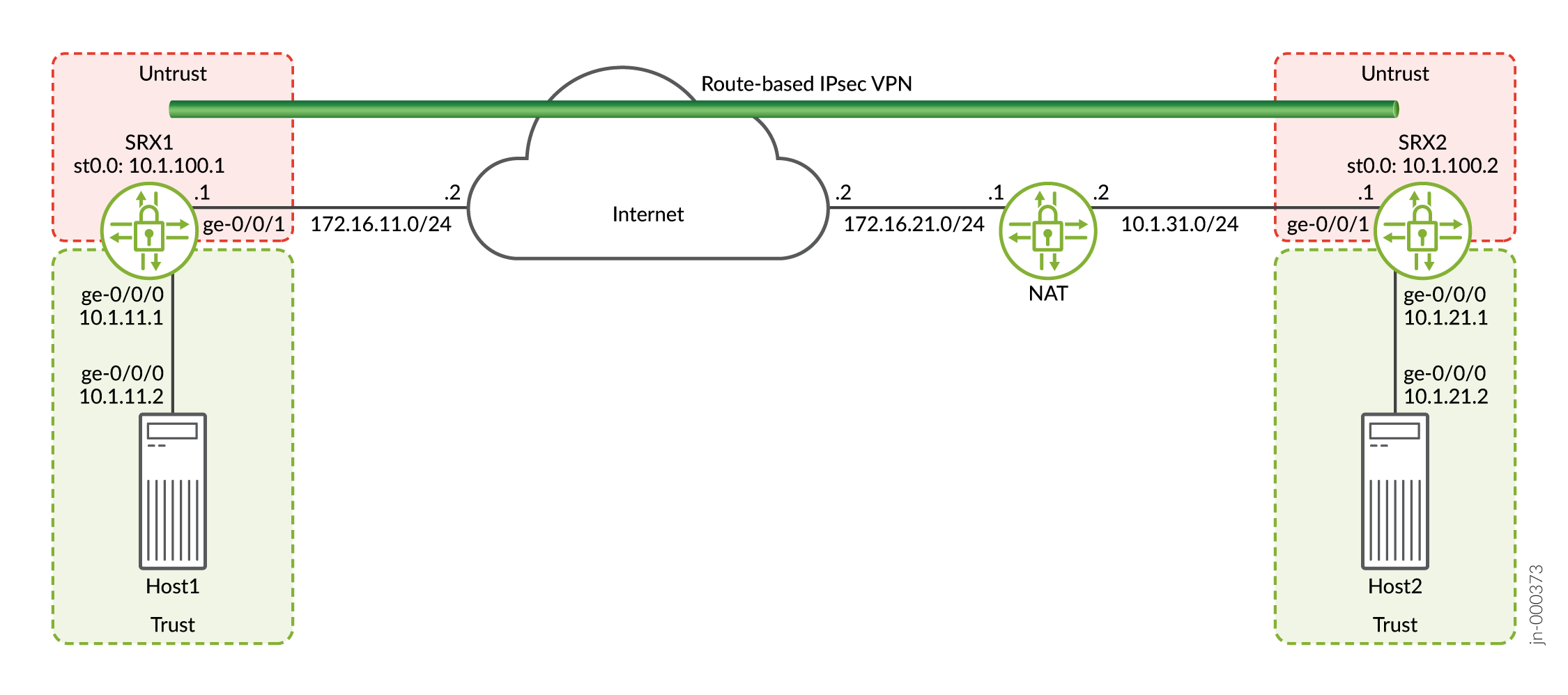
この例では、SRX1 のイニシエータと SRX2 のレスポンダの両方に対して、インターフェイス、IPsec、セキュリティ ポリシーを設定します。次に、IKEフェーズ1およびIPsecフェーズ2のパラメーターを設定します。
SRX1は、宛先アドレスが172.16.21.1のパケットを送信してVPNを確立します。NATデバイスは宛先アドレスを10.1.31.1に変換します。
例でイニシエーターに使用される特定の設定パラメーターについては、 表1 から 表3 を参照してください。
| 機能 |
名前 |
設定パラメータ |
|---|---|---|
| インターフェイス |
ge-0/0/1 |
172.16.11.1/24 |
| ge-0/0/0 |
10.1.11.1/24 |
|
| st0.0(トンネルインターフェイス) |
10.1.100.1/24 |
|
| スタティックルート |
10.1.21.0/24 |
ネクストホップはst0.0です。 |
| 172.16.21.1/32 |
ネクストホップは 172.16.11.2 です。 |
|
| セキュリティゾーン |
信頼できない |
|
| 信頼 |
|
|
| セキュリティポリシー |
SRX2へ |
trustゾーンの10.1.11.0/24からuntrustゾーンの10.1.21.0/24へのトラフィックを許可します。 |
| SRX2から |
untrustゾーンの10.1.21.0/24からtrustゾーンの10.1.11.0/24へのトラフィックを許可します。 |
| 機能 |
名前 |
設定パラメータ |
|---|---|---|
| プロポーザル |
ike_prop |
|
| ポリシー |
ike_pol |
|
| ゲートウェイ |
GW1 |
|
| 機能 |
名前 |
設定パラメータ |
|---|---|---|
| プロポーザル |
ipsec_prop |
|
| ポリシー |
ipsec_pol |
|
| VPN |
VPN1 |
|
例でレスポンダに使用される特定の設定パラメータについては、 表4 から 表6 を参照してください。
| 機能 |
名前 |
設定パラメータ |
|---|---|---|
| インターフェイス |
ge-0/0/1 |
10.1.31.1/24 |
| ge-0/0/0 |
10.1.21.1/24 |
|
| st0.0(トンネルインターフェイス) |
10.1.100.2/24 |
|
| スタティックルート |
172.16.11.1/32 |
ネクストホップは 10.1.31.2 です。 |
| 10.1.11.0/24 |
ネクストホップはst0.0です。 |
|
| セキュリティゾーン |
信頼できない |
|
| 信頼 |
|
|
| セキュリティポリシー |
to-SRX1 |
trustゾーンの10.1.21.0/24からuntrustゾーンの10.1.11.0/24へのトラフィックを許可します。 |
| from-SRX1 |
untrustゾーンの10.1.11.0/24からtrustゾーンの10.1.21.0/24へのトラフィックを許可します。 |
| 機能 |
名前 |
設定パラメータ |
|---|---|---|
| プロポーザル |
ike_prop |
|
| ポリシー |
ike_pol |
|
| ゲートウェイ |
GW1 |
|
| 機能 |
名前 |
設定パラメータ |
|---|---|---|
| プロポーザル |
ipsec_prop |
|
| ポリシー |
ipsec_pol |
|
| VPN |
VPN1 |
|
設定
- SRX1 のインターフェイス、ルーティング オプション、およびセキュリティ パラメーターの設定
- SRX1 の IKE の設定
- SRX1のIPsecの設定
- SRX2のインターフェイス、ルーティングオプション、セキュリティパラメーターの設定
- SRX2 の IKE の設定
- SRX2 の IPsec の設定
- NATデバイスの設定
SRX1 のインターフェイス、ルーティング オプション、およびセキュリティ パラメーターの設定
CLIクイックコンフィグレーション
この例をすばやく設定するには、以下のコマンドをコピーしてテキスト ファイルに貼り付け、改行を削除し、ネットワーク設定に一致させる必要がある詳細情報を変更し、コマンドを [edit] 階層レベルでCLIにコピー アンド ペーストして、設定モードから commit を入力します。
set security address-book book1 address Host1 10.1.11.0/24
set security address-book book1 attach zone trust
set security address-book book2 address Host2 10.1.21.0/24
set security address-book book2 attach zone untrust
set security policies from-zone trust to-zone untrust policy to-SRX2 match source-address Host1
set security policies from-zone trust to-zone untrust policy to-SRX2 match destination-address Host2
set security policies from-zone trust to-zone untrust policy to-SRX2 match application any
set security policies from-zone trust to-zone untrust policy to-SRX2 then permit
set security policies from-zone untrust to-zone trust policy from-SRX2 match source-address Host2
set security policies from-zone untrust to-zone trust policy from-SRX2 match destination-address Host1
set security policies from-zone untrust to-zone trust policy from-SRX2 match application any
set security policies from-zone untrust to-zone trust policy from-SRX2 then permit
set security zones security-zone untrust host-inbound-traffic system-services ike
set security zones security-zone untrust host-inbound-traffic system-services ping
set security zones security-zone untrust interfaces st0.0
set security zones security-zone untrust interfaces ge-0/0/1.0
set security zones security-zone trust host-inbound-traffic system-services all
set security zones security-zone trust host-inbound-traffic protocols all
set security zones security-zone trust interfaces ge-0/0/0.0
set interfaces ge-0/0/0 unit 0 family inet address 10.1.11.1/24
set interfaces ge-0/0/1 unit 0 family inet address 172.16.11.1/24
set interfaces st0 unit 0 family inet address 10.1.100.1/24
set routing-options static route 10.1.21.0/24 next-hop st0.0
set routing-options static route 172.16.21.1/32 next-hop 172.16.11.2
ステップバイステップの手順
次の例では、設定階層のさまざまなレベルに移動する必要があります。その方法の詳細については、『CLIユーザーガイド』の「構成モードでのCLIエディターの使用」を参照してください。
インターフェイス、静的ルート、セキュリティパラメーターを設定するには:
-
VPNに使用されるインターネット、Host1、インターフェイスに接続するインターフェイスを設定します。
[edit]
user@SRX1# set interfaces ge-0/0/0 unit 0 family inet address 10.1.11.1/24
user@SRX1# set interfaces ge-0/0/1 unit 0 family inet address 172.16.11.1/24
user@SRX1# set interfaces st0 unit 0 family inet address 10.1.100.1/24
-
VPNを使用するトラフィックとSRX1の静的ルートを設定して、NATデバイスに到達します。
[edit]
user@SRX1# set routing-options static route 10.1.21.0/24 next-hop st0.0
user@SRX1# set routing-options static route 172.16.21.1/32 next-hop 172.16.11.2
-
untrustセキュリティゾーンを設定します。
[edit]
user@SRX1# set security zones security-zone untrust host-inbound-traffic system-services ike
user@SRX1# set security zones security-zone untrust host-inbound-traffic system-services ping
user@SRX1# set security zones security-zone untrust interfaces st0.0
user@SRX1# set security zones security-zone untrust interfaces ge-0/0/1.0
-
trustセキュリティ ゾーンを設定します。
[edit]
user@SRX1# set security zones security-zone trust host-inbound-traffic system-services all
user@SRX1# set security zones security-zone trust host-inbound-traffic protocols all
user@SRX1# set security zones security-zone trust interfaces ge-0/0/0.0
-
セキュリティポリシーで使用されるネットワークのアドレス帳を設定します。
[edit]
user@SRX1# set security address-book book1 address Host1 10.1.11.0/24
user@SRX1# set security address-book book1 attach zone trust
user@SRX1# set security address-book book2 address Host2 10.1.21.0/24
user@SRX1# set security address-book book2 attach zone untrust
-
セキュリティポリシーを設定して、ホスト間のトラフィックを許可します。
[edit]
user@SRX1# set security policies from-zone trust to-zone untrust policy to-SRX2 match source-address Host1
user@SRX1# set security policies from-zone trust to-zone untrust policy to-SRX2 match destination-address Host2
user@SRX1# set security policies from-zone trust to-zone untrust policy to-SRX2 match application any
user@SRX1# set security policies from-zone trust to-zone untrust policy to-SRX2 then permit
user@SRX1# set security policies from-zone untrust to-zone trust policy from-SRX2 match source-address Host2
user@SRX1# set security policies from-zone untrust to-zone trust policy from-SRX2 match destination-address Host1
user@SRX1# set security policies from-zone untrust to-zone trust policy from-SRX2 match application any
user@SRX1# set security policies from-zone untrust to-zone trust policy from-SRX2 then permit
結果
設定モードから、 show interfaces、 show routing-options、 show security コマンドを入力して設定を確認します。出力に意図した設定が表示されない場合は、この例の手順を繰り返して設定を修正します。
[edit]
user@SRX1# show interfaces
ge-0/0/0 {
    unit 0 {
        family inet {
            address 10.1.11.1/24;
        }
    }
}
ge-0/0/1 {
    unit 0 {
        family inet {
            address 172.16.11.1/24;
        }
    }
}
st0 {
    unit 0 {
        family inet {
            address 10.1.100.1/24;
        }
    }
}
[edit]
user@SRX1# show routing-options
static {
    route 10.1.21.0/24 next-hop st0.0;
    route 172.16.21.1/32 next-hop 172.16.11.2;
}
[edit]
user@SRX1# show security
address-book {
    book1 {
        address Host1 10.1.11.0/24;
        attach {
            zone trust;
        }
    }
    book2 {
        address Host2 10.1.21.0/24;
        attach {
            zone untrust;
        }
    }
}
policies {
    from-zone trust to-zone untrust {
        policy to-SRX2 {
            match {
                source-address Host1;
                destination-address Host2;
                application any;
            }
            then {
                permit;
            }
        }
    }
    from-zone untrust to-zone trust {
        policy from-SRX2 {
            match {
                source-address Host2;
                destination-address Host1;
                application any;
            }
            then {
                permit;
            }
        }
    }
}
zones {
    security-zone untrust {
        host-inbound-traffic {
            system-services {
                ike;
                ping;
            }
        }
        interfaces {
            st0.0;
            ge-0/0/1.0;
        }
    }
    security-zone trust {
        host-inbound-traffic {
            system-services {
                all;
            }
            protocols {
                all;
            }
        }
        interfaces {
            ge-0/0/0.0;
        }
    }
}
デバイスの設定が完了したら、設定モードから commit を入力します。
SRX1 の IKE の設定
CLIクイックコンフィグレーション
この例をすばやく設定するには、以下のコマンドをコピーしてテキスト ファイルに貼り付け、改行を削除し、ネットワーク設定に一致させる必要がある詳細情報を変更し、コマンドを [edit] 階層レベルでCLIにコピー アンド ペーストして、設定モードから commit を入力します。
set security ike proposal ike_prop authentication-method pre-shared-keys
set security ike proposal ike_prop dh-group group2
set security ike proposal ike_prop authentication-algorithm sha1
set security ike proposal ike_prop encryption-algorithm 3des-cbc
set security ike policy ike_pol mode main
set security ike policy ike_pol proposals ike_prop
set security ike policy ike_pol pre-shared-key ascii-text “$ABC123”
set security ike gateway gw1 ike-policy ike_pol
set security ike gateway gw1 address 172.16.21.1
set security ike gateway gw1 local-identity user-at-hostname "srx1@example.com"
set security ike gateway gw1 remote-identity user-at-hostname "srx2@example.com"
set security ike gateway gw1 external-interface ge-0/0/1.0
ステップバイステップの手順
次の例では、設定階層のさまざまなレベルに移動する必要があります。その方法の詳細については、『CLIユーザーガイド』の「構成モードでのCLIエディターの使用」を参照してください。
IKEを設定するには:
-
IKEフェーズ1のプロポーザルを作成します。
[edit]
user@SRX1# set security ike proposal ike_prop authentication-method pre-shared-keys
user@SRX1# set security ike proposal ike_prop dh-group group2
user@SRX1# set security ike proposal ike_prop authentication-algorithm sha1
user@SRX1# set security ike proposal ike_prop encryption-algorithm 3des-cbc
-
IKEフェーズ1ポリシーを作成します。
[edit]
user@SRX1# set security ike policy ike_pol mode main
user@SRX1# set security ike policy ike_pol proposals ike_prop
user@SRX1# set security ike policy ike_pol pre-shared-key ascii-text “$ABC123”
-
IKEフェーズ1ゲートウェイパラメータを設定します。ゲートウェイアドレスは、NATデバイスのIPである必要があります。
[edit security ike gateway gw1]
user@SRX1# set security ike gateway gw1 ike-policy ike_pol
user@SRX1# set security ike gateway gw1 address 172.16.21.1
user@SRX1# set security ike gateway gw1 local-identity user-at-hostname "srx1@example.com"
user@SRX1# set security ike gateway gw1 remote-identity user-at-hostname "srx2@example.com"
user@SRX1# set security ike gateway gw1 external-interface ge-0/0/1.0
結果
設定モードから、 show security ike コマンドを入力して設定を確認します。出力に意図した設定が表示されない場合は、この例の手順を繰り返して設定を修正します。
[edit]
user@SRX1# show security ike
proposal ike_prop {
    authentication-method pre-shared-keys;
    dh-group group2;
    authentication-algorithm sha1;
    encryption-algorithm 3des-cbc;
}
policy ike_pol {
    mode main;
    proposals ike_prop;
    pre-shared-key ascii-text “$9$xPn7-VwsgaJUHqp01IcSs2g”; ## SECRET-DATA
}
gateway gw1 {
    ike-policy ike_pol;
    address 172.16.21.1;
    local-identity user-at-hostname "srx1@example.com";
    remote-identity user-at-hostname "srx2@example.com";
    external-interface ge-0/0/1.0;
}
デバイスの設定が完了したら、設定モードから commit を入力します。
SRX1のIPsecの設定
CLIクイックコンフィグレーション
この例をすばやく設定するには、以下のコマンドをコピーしてテキスト ファイルに貼り付け、改行を削除し、ネットワーク設定に一致させる必要がある詳細情報を変更し、コマンドを [edit] 階層レベルでCLIにコピー アンド ペーストして、設定モードから commit を入力します。
set security ipsec proposal ipsec_prop protocol esp
set security ipsec proposal ipsec_prop authentication-algorithm hmac-sha1-96
set security ipsec proposal ipsec_prop encryption-algorithm 3des-cbc
set security ipsec policy ipsec_pol perfect-forward-secrecy keys group2
set security ipsec policy ipsec_pol proposals ipsec_prop
set security ipsec vpn vpn1 bind-interface st0.0
set security ipsec vpn vpn1 ike gateway gw1
set security ipsec vpn vpn1 ike ipsec-policy ipsec_pol
set security ipsec vpn vpn1 establish-tunnels immediately
ステップバイステップの手順
次の例では、設定階層のさまざまなレベルに移動する必要があります。その方法の詳細については、『CLIユーザーガイド』の「構成モードでのCLIエディターの使用」を参照してください。
IPsecを設定するには:
-
IPsecフェーズ2のプロポーザルを作成します。
[edit]
user@SRX1# set security ipsec proposal ipsec_prop protocol esp
user@SRX1# set security ipsec proposal ipsec_prop authentication-algorithm hmac-sha1-96
user@SRX1# set security ipsec proposal ipsec_prop encryption-algorithm 3des-cbc
-
IPsecフェーズ2のポリシーを作成します。
[edit]
user@SRX1# set security ipsec policy ipsec_pol perfect-forward-secrecy keys group2
user@SRX1# set security ipsec policy ipsec_pol proposals ipsec_prop
-
IPsec VPNパラメーターを設定します。
[edit]
user@SRX1# set security ipsec vpn vpn1 bind-interface st0.0
user@SRX1# set security ipsec vpn vpn1 ike gateway gw1
user@SRX1# set security ipsec vpn vpn1 ike ipsec-policy ipsec_pol
user@SRX1# set security ipsec vpn vpn1 establish-tunnels immediately
結果
設定モードから、 show security ipsec コマンドを入力して設定を確認します。出力に意図した設定が表示されない場合は、この例の手順を繰り返して設定を修正します。
[edit]
user@SRX1# show security ipsec
proposal ipsec_prop {
    protocol esp;
    authentication-algorithm hmac-sha1-96;
    encryption-algorithm 3des-cbc;
}
policy ipsec_pol {
    perfect-forward-secrecy {
        keys group2;
    }
    proposals ipsec_prop;
}
vpn vpn1 {
    bind-interface st0.0;
    ike {
        gateway gw1;
        ipsec-policy ipsec_pol;
    }
    establish-tunnels immediately;
}
デバイスの設定が完了したら、設定モードから commit を入力します。
SRX2のインターフェイス、ルーティングオプション、セキュリティパラメーターの設定
CLIクイックコンフィグレーション
この例をすばやく設定するには、以下のコマンドをコピーしてテキスト ファイルに貼り付け、改行を削除し、ネットワーク設定に一致させる必要がある詳細情報を変更し、コマンドを [edit] 階層レベルでCLIにコピー アンド ペーストして、設定モードから commit を入力します。
set security address-book book1 address Host2 10.1.21.0/24
set security address-book book1 attach zone trust
set security address-book book2 address Host1 10.1.11.0/24
set security address-book book2 attach zone untrust
set security policies from-zone trust to-zone untrust policy to-SRX1 match source-address Host2
set security policies from-zone trust to-zone untrust policy to-SRX1 match destination-address Host1
set security policies from-zone trust to-zone untrust policy to-SRX1 match application any
set security policies from-zone trust to-zone untrust policy to-SRX1 then permit
set security policies from-zone untrust to-zone trust policy from-SRX1 match source-address Host1
set security policies from-zone untrust to-zone trust policy from-SRX1 match destination-address Host2
set security policies from-zone untrust to-zone trust policy from-SRX1 match application any
set security policies from-zone untrust to-zone trust policy from-SRX1 then permit
set security zones security-zone untrust host-inbound-traffic system-services ike
set security zones security-zone untrust host-inbound-traffic system-services ping
set security zones security-zone untrust interfaces ge-0/0/1.0
set security zones security-zone untrust interfaces st0.0
set security zones security-zone trust host-inbound-traffic system-services all
set security zones security-zone trust host-inbound-traffic protocols all
set security zones security-zone trust interfaces ge-0/0/0.0
set interfaces ge-0/0/0 unit 0 family inet address 10.1.21.1/24
set interfaces ge-0/0/1 unit 0 family inet address 10.1.31.1/24
set interfaces st0 unit 0 family inet address 10.1.100.2/24
set routing-options static route 172.16.11.1/32 next-hop 10.1.31.2
set routing-options static route 10.1.11.0/24 next-hop st0.0
ステップバイステップの手順
次の例では、設定階層のさまざまなレベルに移動する必要があります。その方法の詳細については、『CLIユーザーガイド』の「構成モードでのCLIエディターの使用」を参照してください。
インターフェイス、静的ルート、セキュリティパラメーターを設定するには:
-
インターネット、Host2、およびVPNに使用されるインターフェイスに接続するインターフェイスを設定します。
[edit]
user@SRX2# set interfaces ge-0/0/0 unit 0 family inet address 10.1.21.1/24
user@SRX2# set interfaces ge-0/0/1 unit 0 family inet address 10.1.31.1/24
user@SRX2# set interfaces st0 unit 0 family inet address 10.1.100.2/24
-
VPNを使用するトラフィックとSRX2の静的ルートを設定してSRX1に到達します。
[edit]
user@SRX2# set routing-options static route 172.16.11.1/32 next-hop 10.1.31.2
user@SRX2# set routing-options static route 10.1.11.0/24 next-hop st0.0
-
untrustセキュリティゾーンを設定します。
[edit]
user@SRX2# set security zones security-zone untrust host-inbound-traffic system-services ike
user@SRX2# set security zones security-zone untrust host-inbound-traffic system-services ping
user@SRX2# set security zones security-zone untrust interfaces ge-0/0/1.0
user@SRX2# set security zones security-zone untrust interfaces st0.0
-
trustセキュリティ ゾーンを設定します。
[edit]
user@SRX2# set security zones security-zone trust host-inbound-traffic system-services all
user@SRX2# set security zones security-zone trust host-inbound-traffic protocols all
user@SRX2# set security zones security-zone trust interfaces ge-0/0/0.0
-
セキュリティポリシーで使用されるネットワークのアドレス帳を設定します。
[edit]
user@SRX2# set security address-book book1 address Host2 10.1.21.0/24
user@SRX2# set security address-book book1 attach zone trust
user@SRX2# set security address-book book2 address Host1 10.1.11.0/24
user@SRX2# set security address-book book2 attach zone untrust
-
セキュリティポリシーを設定して、ホスト間のトラフィックを許可します。
[edit]
user@SRX2# set security policies from-zone trust to-zone untrust policy to-SRX1 match source-address Host2
user@SRX2# set security policies from-zone trust to-zone untrust policy to-SRX1 match destination-address Host1
user@SRX2# set security policies from-zone trust to-zone untrust policy to-SRX1 match application any
user@SRX2# set security policies from-zone trust to-zone untrust policy to-SRX1 then permit
user@SRX2# set security policies from-zone untrust to-zone trust policy from-SRX1 match source-address Host1
user@SRX2# set security policies from-zone untrust to-zone trust policy from-SRX1 match destination-address Host2
user@SRX2# set security policies from-zone untrust to-zone trust policy from-SRX1 match application any
user@SRX2# set security policies from-zone untrust to-zone trust policy from-SRX1 then permit
結果
設定モードから、 show interfaces、 show routing-options、 show security コマンドを入力して設定を確認します。出力に意図した設定が表示されない場合は、この例の手順を繰り返して設定を修正します。
[edit]
user@SRX2# show interfaces
ge-0/0/0 {
    unit 0 {
        family inet {
            address 10.1.21.1/24;
        }
    }
}
ge-0/0/1 {
    unit 0 {
        family inet {
            address 10.1.31.1/24;
        }
    }
}
st0 {
    unit 0 {
        family inet {
            address 10.1.100.2/24;
        }
    }
}
[edit]
user@SRX2# show routing-options
static {
    route 172.16.11.1/32 next-hop 10.1.31.2;
    route 10.1.11.0/24 next-hop st0.0;
}
[edit]
user@SRX2# show security
address-book {
    book1 {
        address Host2 10.1.21.0/24;
        attach {
            zone trust;
        }
    }
    book2 {
        address Host1 10.1.11.0/24;
        attach {
            zone untrust;
        }
    }
}
policies {
    from-zone trust to-zone untrust {
        policy to-SRX1 {
            match {
                source-address Host2;
                destination-address Host1;
                application any;
            }
            then {
                permit;
            }
        }
    }
    from-zone untrust to-zone trust {
        policy from-SRX1 {
            match {
                source-address Host1;
                destination-address Host2;
                application any;
            }
            then {
                permit;
            }
        }
    }
}
zones {
    security-zone untrust {
        host-inbound-traffic {
            system-services {
                ike;
                ping;
            }
        }
        interfaces {
            ge-0/0/1.0;
            st0.0;
        }
    }
    security-zone trust {
        host-inbound-traffic {
            system-services {
                all;
            }
            protocols {
                all;
            }
        }
        interfaces {
            ge-0/0/0.0;
        }
    }
}
デバイスの設定が完了したら、設定モードから commit を入力します。
SRX2 の IKE の設定
CLIクイックコンフィグレーション
この例をすばやく設定するには、以下のコマンドをコピーしてテキスト ファイルに貼り付け、改行を削除し、ネットワーク設定に一致させる必要がある詳細情報を変更し、コマンドを [edit] 階層レベルでCLIにコピー アンド ペーストして、設定モードから commit を入力します。
set security ike proposal ike_prop authentication-method pre-shared-keys
set security ike proposal ike_prop dh-group group2
set security ike proposal ike_prop authentication-algorithm sha1
set security ike proposal ike_prop encryption-algorithm 3des-cbc
set security ike policy ike_pol mode main
set security ike policy ike_pol proposals ike_prop
set security ike policy ike_pol pre-shared-key ascii-text “$ABC123”
set security ike gateway gw1 ike-policy ike_pol
set security ike gateway gw1 address 172.16.11.1
set security ike gateway gw1 local-identity user-at-hostname "srx2@example.com"
set security ike gateway gw1 remote-identity user-at-hostname "srx1@example.com"
set security ike gateway gw1 external-interface ge-0/0/1.0
ステップバイステップの手順
次の例では、設定階層のさまざまなレベルに移動する必要があります。その方法の詳細については、『CLIユーザーガイド』の「構成モードでのCLIエディターの使用」を参照してください。
IKEを設定するには:
-
IKEフェーズ1のプロポーザルを作成します。
[edit]
user@SRX2# set security ike proposal ike_prop authentication-method pre-shared-keys
user@SRX2# set security ike proposal ike_prop dh-group group2
user@SRX2# set security ike proposal ike_prop authentication-algorithm sha1
user@SRX2# set security ike proposal ike_prop encryption-algorithm 3des-cbc
-
IKEフェーズ1ポリシーを作成します。
[edit]
user@SRX2# set security ike policy ike_pol mode main
user@SRX2# set security ike policy ike_pol proposals ike_prop
user@SRX2# set security ike policy ike_pol pre-shared-key ascii-text “$ABC123”
-
IKEフェーズ1ゲートウェイパラメータを設定します。ゲートウェイアドレスはSRX1のIPである必要があります。
[edit]
user@SRX2# set security ike gateway gw1 ike-policy ike_pol
user@SRX2# set security ike gateway gw1 address 172.16.11.1
user@SRX2# set security ike gateway gw1 local-identity user-at-hostname "srx2@example.com"
user@SRX2# set security ike gateway gw1 remote-identity user-at-hostname "srx1@example.com"
user@SRX2# set security ike gateway gw1 external-interface ge-0/0/1.0
結果
設定モードから、 show security ike コマンドを入力して設定を確認します。出力に意図した設定が表示されない場合は、この例の手順を繰り返して設定を修正します。
[edit]
user@SRX2# show security ike
proposal ike_prop {
    authentication-method pre-shared-keys;
    dh-group group2;
    authentication-algorithm sha1;
    encryption-algorithm 3des-cbc;
}
policy ike_pol {
    mode main;
    proposals ike_prop;
    pre-shared-key ascii-text "$9$mP5QF3/At0IE-VsYoa36/"; ## SECRET-DATA
}
gateway gw1 {
    ike-policy ike_pol;
    address 172.16.11.1;
    local-identity user-at-hostname "srx2@example.com";
    remote-identity user-at-hostname "srx1@example.com";
    external-interface ge-0/0/1.0;
}
デバイスの設定が完了したら、設定モードから commit を入力します。
SRX2 の IPsec の設定
CLIクイックコンフィグレーション
この例をすばやく設定するには、以下のコマンドをコピーしてテキスト ファイルに貼り付け、改行を削除し、ネットワーク設定に一致させる必要がある詳細情報を変更し、コマンドを [edit] 階層レベルでCLIにコピー アンド ペーストして、設定モードから commit を入力します。
set security ipsec proposal ipsec_prop protocol esp
set security ipsec proposal ipsec_prop authentication-algorithm hmac-sha1-96
set security ipsec proposal ipsec_prop encryption-algorithm 3des-cbc
set security ipsec policy ipsec_pol perfect-forward-secrecy keys group2
set security ipsec policy ipsec_pol proposals ipsec_prop
set security ipsec vpn vpn1 bind-interface st0.0
set security ipsec vpn vpn1 ike gateway gw1
set security ipsec vpn vpn1 ike ipsec-policy ipsec_pol
set security ipsec vpn vpn1 establish-tunnels immediately
ステップバイステップの手順
次の例では、設定階層のさまざまなレベルに移動する必要があります。その方法の詳細については、『CLIユーザーガイド』の「構成モードでのCLIエディターの使用」を参照してください。
IPsecを設定するには:
-
IPsecフェーズ2のプロポーザルを作成します。
[edit]
user@SRX2# set security ipsec proposal ipsec_prop protocol esp
user@SRX2# set security ipsec proposal ipsec_prop authentication-algorithm hmac-sha1-96
user@SRX2# set security ipsec proposal ipsec_prop encryption-algorithm 3des-cbc
-
IPsecフェーズ2のポリシーを作成します。
[edit]
user@SRX2# set security ipsec policy ipsec_pol perfect-forward-secrecy keys group2
user@SRX2# set security ipsec policy ipsec_pol proposals ipsec_prop
-
IPsec VPNパラメーターを設定します。
[edit]
user@SRX2# set security ipsec vpn vpn1 bind-interface st0.0
user@SRX2# set security ipsec vpn vpn1 ike gateway gw1
user@SRX2# set security ipsec vpn vpn1 ike ipsec-policy ipsec_pol
user@SRX2# set security ipsec vpn vpn1 establish-tunnels immediately
結果
設定モードから、 show security ipsec コマンドを入力して設定を確認します。出力に意図した設定が表示されない場合は、この例の手順を繰り返して設定を修正します。
[edit]
user@SRX2# show security ipsec
proposal ipsec_prop {
    protocol esp;
    authentication-algorithm hmac-sha1-96;
    encryption-algorithm 3des-cbc;
}
policy ipsec_pol {
    perfect-forward-secrecy {
        keys group2;
    }
    proposals ipsec_prop;
}
vpn vpn1 {
    bind-interface st0.0;
    ike {
        gateway gw1;
        ipsec-policy ipsec_pol;
    }
    establish-tunnels immediately;
}
デバイスの設定が完了したら、設定モードから commit を入力します。
NATデバイスの設定
CLIクイックコンフィグレーション
この例では、静的 NAT を使用しています。静的 NAT は双方向性であるため、10.1.31.1 から 172.16.11.1 へのトラフィックも同じ NAT 設定を使用します。
この例をすばやく設定するには、以下のコマンドをコピーしてテキストファイルに貼り付け、改行を削除し、ネットワーク設定に一致させる必要がある詳細情報を変更し、コマンドを [edit] 階層レベルでCLIにコピーアンドペーストして、設定モードから commit を入力します。
set security nat static rule-set rule1 from zone untrust
set security nat static rule-set rule1 rule ipsec match source-address 172.16.11.1/32
set security nat static rule-set rule1 rule ipsec match destination-address 172.16.21.1/32
set security nat static rule-set rule1 rule ipsec then static-nat prefix 10.1.31.1/32
set security policies from-zone trust to-zone untrust policy allow-out match source-address any
set security policies from-zone trust to-zone untrust policy allow-out match destination-address any
set security policies from-zone trust to-zone untrust policy allow-out match application any
set security policies from-zone trust to-zone untrust policy allow-out then permit
set security policies from-zone untrust to-zone trust policy allow-out-in match source-address any
set security policies from-zone untrust to-zone trust policy allow-out-in match destination-address any
set security policies from-zone untrust to-zone trust policy allow-out-in match application any
set security policies from-zone untrust to-zone trust policy allow-out-in then permit
set security zones security-zone trust host-inbound-traffic system-services ping
set security zones security-zone trust interfaces ge-0/0/1.0
set security zones security-zone untrust host-inbound-traffic system-services ping
set security zones security-zone untrust interfaces ge-0/0/0.0
set interfaces ge-0/0/0 unit 0 family inet address 172.16.21.1/24
set interfaces ge-0/0/1 unit 0 family inet address 10.1.31.2/24
set routing-options static route 172.16.11.0/24 next-hop 172.16.21.2
検証
設定が正常に機能していることを確認するには、以下のタスクを実行します。
- SRX1 の IKE フェーズ 1 ステータスの確認
- SRX1 での IPsec セキュリティ アソシエーションの確認
- SRX2 の IKE フェーズ 1 ステータスの確認
- SRX2 での IPsec セキュリティ アソシエーションの検証
- ホスト間到達可能性の検証
SRX1 の IKE フェーズ 1 ステータスの確認
目的
IKEフェーズ1ステータスを確認します。
アクション
動作モードから、 show security ike security-associations コマンドを入力します。より詳細な出力には、 show security ike security-associations detail コマンドを使用します。
user@SRX1> show security ike security-associations
Index   State  Initiator cookie  Responder cookie  Mode           Remote Address
302301  UP     84e8fc61d0750278  ea9a07ef032805b6  Main           172.16.21.1
user@SRX1> show security ike security-associations detail
IKE peer 172.16.21.1, Index 302301, Gateway Name: gw1
  Role: Initiator, State: UP
  Initiator cookie: 84e8fc61d0750278, Responder cookie: ea9a07ef032805b6
  Exchange type: Main, Authentication method: Pre-shared-keys
  Local: 172.16.11.1:4500, Remote: 172.16.21.1:4500
  Lifetime: Expires in 19657 seconds
  Reauth Lifetime: Disabled
  IKE Fragmentation: Disabled, Size: 0
  Remote Access Client Info: Unknown Client
  Peer ike-id: srx2@example.com
  AAA assigned IP: 0.0.0.0
  Algorithms:
   Authentication        : hmac-sha1-96
   Encryption            : 3des-cbc
   Pseudo random function: hmac-sha1
   Diffie-Hellman group  : DH-group-2
  Traffic statistics:
   Input  bytes  :                 1780
   Output bytes  :                 2352
   Input  packets:                    7
   Output packets:                   14
   Input  fragmentated packets:       0
   Output fragmentated packets:       0
  IPSec security associations: 4 created, 0 deleted
  Phase 2 negotiations in progress: 1

    Negotiation type: Quick mode, Role: Initiator, Message ID: 0
    Local: 172.16.11.1:4500, Remote: 172.16.21.1:4500
    Local identity: srx1@example.com
    Remote identity: srx2@example.com
    Flags: IKE SA is created
意味
show security ike security-associationsコマンドは、すべてのアクティブなIKEフェーズ1のSAを一覧表示します。SAが表示されない場合は、フェーズ1の確立に問題があったことを示しています。設定でIKEポリシーパラメータと外部インターフェイスの設定を確認してください。
SAが表示される場合は、以下の情報を確認します。
-
インデックス—この値はIKE SAごとに固有で、
show security ike security-associations index detailコマンドで使用すると、SAに関する詳細情報を得ることができます。 -
リモートアドレス—リモートIPアドレスが正しく、ポート4500がピアツーピア通信に使用されていることを確認します。NAT-T は、ポート 4500 で UDP 内の IKE トラフィックと ESP トラフィックの両方をカプセル化することを忘れないでください。
-
ロールイニシエータの状態
-
Up—フェーズ1 SAが確立されています。
-
Down - フェーズ 1 SA の確立に問題がありました。
-
IPsec SAペアの両方のピアがポート4500を使用しています。
-
ピア IKE ID—リモート アドレスが正しいことを確認します。
-
ローカルIDとリモートID—これらが正しいことを確認します。
-
-
モード—正しいモードが使用されていることを確認します。
設定で以下が適切か検証します。
-
外部インターフェイス(インターフェイスはIKEパケットを受信するインターフェイスである必要があります)
-
IKEポリシーパラメータ
-
事前共有鍵情報
-
フェーズ1のプロポーザルパラメーター(両方のピアで一致する必要があります)
show security ike security-associationsコマンドは、セキュリティアソシエーションに関する以下の追加情報を一覧表示します。
-
使用される認証および暗号化アルゴリズム
-
フェーズ1のライフタイム
-
トラフィック統計情報(トラフィックが双方向に正しく流れていることを検証するために使用できます)
-
ロール情報
トラブルシューティングは、レスポンダ ロールを使用してピア上で実行するのが最適です。
-
開始側と応答側の情報
-
作成されたIPsec SAの数
-
進行中のフェーズ2ネゴシエーションの数
SRX1 での IPsec セキュリティ アソシエーションの確認
目的
IPsecステータスを確認します。
アクション
動作モードから、 show security ipsec security-associations コマンドを入力します。より詳細な出力には、 show security ipsec security-associations detail コマンドを使用します。
user@SRX1> show security ipsec security-associations
  Total active tunnels: 1     Total Ipsec sas: 1
  ID    Algorithm       SPI      Life:sec/kb  Mon lsys Port  Gateway
  <131073 ESP:3des/sha1   fc5dbac4 2160/ unlim  -   root 4500  172.16.21.1
  >131073 ESP:3des/sha1   45fed9d8 2160/ unlim  -   root 4500  172.16.21.1
user@SRX1> show security ipsec security-associations detail
ID: 131073 Virtual-system: root, VPN Name: vpn1
  Local Gateway: 172.16.11.1, Remote Gateway: 172.16.21.1
  Local Identity: ipv4_subnet(any:0,[0..7]=0.0.0.0/0)
  Remote Identity: ipv4_subnet(any:0,[0..7]=0.0.0.0/0)
  Version: IKEv1
  DF-bit: clear, Copy-Outer-DSCP Disabled, Bind-interface: st0.0
  Port: 4500, Nego#: 7, Fail#: 0, Def-Del#: 0 Flag: 0x600a29
  Multi-sa, Configured SAs# 1, Negotiated SAs#: 1
  Tunnel events:
    Fri Jul 22 2022 11:07:40 -0700: IPSec SA rekey successfully completed (3 times)
    Fri Jul 22 2022 08:38:41 -0700: IPSec SA negotiation successfully completed (1 times)
    Fri Jul 22 2022 08:38:41 -0700: User cleared IPSec SA from CLI (1 times)
    Fri Jul 22 2022 08:38:41 -0700: IKE SA negotiation successfully completed (3 times)
    Fri Jul 22 2022 08:38:26 -0700: IPSec SA negotiation successfully completed (1 times)
    Fri Jul 22 2022 08:38:26 -0700: User cleared IPSec SA from CLI (1 times)
    Fri Jul 22 2022 08:38:25 -0700: IPSec SA negotiation successfully completed (1 times)
    Fri Jul 22 2022 08:38:24 -0700: User cleared IPSec SA from CLI (1 times)
    Fri Jul 22 2022 08:37:37 -0700: IPSec SA negotiation successfully completed (1 times)
  Direction: inbound, SPI: fc5dbac4, AUX-SPI: 0
                              , VPN Monitoring: -
    Hard lifetime: Expires in 2153 seconds
    Lifesize Remaining:  Unlimited
    Soft lifetime: Expires in 1532 seconds
    Mode: Tunnel(0 0), Type: dynamic, State: installed
    Protocol: ESP, Authentication: hmac-sha1-96, Encryption: 3des-cbc
    Anti-replay service: counter-based enabled, Replay window size: 64
  Direction: outbound, SPI: 45fed9d8, AUX-SPI: 0
                              , VPN Monitoring: -
    Hard lifetime: Expires in 2153 seconds
    Lifesize Remaining:  Unlimited
    Soft lifetime: Expires in 1532 seconds
    Mode: Tunnel(0 0), Type: dynamic, State: installed
    Protocol: ESP, Authentication: hmac-sha1-96, Encryption: 3des-cbc
    Anti-replay service: counter-based enabled, Replay window size: 64
意味
show security ipsec security-associationsコマンドからの出力には、以下の情報が表示されます。
-
リモートゲートウェイのアドレスは172.16.21.1です。
-
IPsec SAペアの両方のピアがポート4500を使用しています。
-
両方向のSPI、ライフタイム(秒)、使用制限(またはKBで示したライフサイズ)が表示されます。2160/ unlim値は、フェーズ2のライフタイムが2160秒で期限が切れ、ライフサイズが指定されていないことを示し、無制限であることを示しています。フェーズ2のライフタイムはフェーズ1のライフタイムと異なる場合があります。これはVPNが起動した後にフェーズ2はフェーズ1に依存しないためです。
-
月曜の列にあるハイフンで示されているように、このSAではVPN監視が有効になっていません。VPN監視が有効な場合、Uは監視が稼働していることを示し、Dは監視が停止していることを示します。
-
仮想システム(vsys)はルート システムであり、常に 0 が表示されます。
SRX2 の IKE フェーズ 1 ステータスの確認
目的
IKEフェーズ1ステータスを確認します。
アクション
動作モードから、 show security ike security-associations コマンドを入力します。より詳細な出力には、 show security ike security-associations detail コマンドを使用します。
user@SRX2> show security ike security-associations
Index   State  Initiator cookie  Responder cookie  Mode           Remote Address
5567091 UP     84e8fc61d0750278  ea9a07ef032805b6  Main           172.16.11.1
user@SRX2> show security ike security-associations detail
IKE peer 172.16.11.1, Index 5567091, Gateway Name: gw1
  Role: Responder, State: UP
  Initiator cookie: 84e8fc61d0750278, Responder cookie: ea9a07ef032805b6
  Exchange type: Main, Authentication method: Pre-shared-keys
  Local: 10.1.31.1:4500, Remote: 172.16.11.1:4500
  Lifetime: Expires in 18028 seconds
  Reauth Lifetime: Disabled
  IKE Fragmentation: Disabled, Size: 0
  Remote Access Client Info: Unknown Client
  Peer ike-id: srx1@example.com
  AAA assigned IP: 0.0.0.0
  Algorithms:
   Authentication        : hmac-sha1-96
   Encryption            : 3des-cbc
   Pseudo random function: hmac-sha1
   Diffie-Hellman group  : DH-group-2
  Traffic statistics:
   Input  bytes  :                 2352
   Output bytes  :                 1780
   Input  packets:                   14
   Output packets:                    7
   Input  fragmentated packets:       0
   Output fragmentated packets:       0
  IPSec security associations: 4 created, 3 deleted
  Phase 2 negotiations in progress: 1

    Negotiation type: Quick mode, Role: Responder, Message ID: 0
    Local: 10.1.31.1:4500, Remote: 172.16.11.1:4500
    Local identity: srx2@example.com
    Remote identity: srx1@example.com
    Flags: IKE SA is created
意味
show security ike security-associationsコマンドは、すべてのアクティブなIKEフェーズ1のSAを一覧表示します。SAが表示されない場合は、フェーズ1の確立に問題があったことを示しています。設定でIKEポリシーパラメータと外部インターフェイスの設定を確認してください。
SAが表示される場合は、以下の情報を確認します。
-
インデックス—この値はIKE SAごとに固有で、
show security ike security-associations detailコマンドで使用すると、SAに関する詳細情報を得ることができます。 -
リモートアドレス—リモートIPアドレスが正しく、ポート4500がピアツーピア通信に使用されていることを確認します。
-
ロールレスポンダーの状態
-
Up:フェーズ1SAが確立されました。
-
Down - フェーズ 1 SA の確立に問題がありました。
-
ピア IKE ID—アドレスが正しいことを確認します。
-
ローカルIDとリモートID—これらのアドレスが正しいことを確認してください。
-
-
モード—正しいモードが使用されていることを確認します。
設定で以下が適切か検証します。
-
外部インターフェイス(インターフェイスはIKEパケットを受信するインターフェイスである必要があります)
-
IKEポリシーパラメータ
-
事前共有鍵情報
-
フェーズ1のプロポーザルパラメーター(両方のピアで一致する必要があります)
show security ike security-associationsコマンドは、セキュリティアソシエーションに関する以下の追加情報を一覧表示します。
-
使用される認証および暗号化アルゴリズム
-
フェーズ1のライフタイム
-
トラフィック統計情報(トラフィックが双方向に正しく流れていることを検証するために使用できます)
-
ロール情報
トラブルシューティングは、レスポンダ ロールを使用してピア上で実行するのが最適です。
-
開始側と応答側の情報
-
作成されたIPsec SAの数
-
進行中のフェーズ2ネゴシエーションの数
SRX2 での IPsec セキュリティ アソシエーションの検証
目的
IPsecステータスを確認します。
アクション
動作モードから、 show security ipsec security-associations コマンドを入力します。より詳細な出力には、 show security ipsec security-associations detail コマンドを使用します。
user@SRX2> show security ipsec security-associations
  Total active tunnels: 1     Total Ipsec sas: 1
  ID    Algorithm       SPI      Life:sec/kb  Mon lsys Port  Gateway
  <131073 ESP:3des/sha1   45fed9d8 1526/ unlim  -   root 4500  172.16.11.1
  >131073 ESP:3des/sha1   fc5dbac4 1526/ unlim  -   root 4500  172.16.11.1
user@SRX2> show security ipsec security-associations detail
ID: 131073 Virtual-system: root, VPN Name: vpn1
  Local Gateway: 10.1.31.1, Remote Gateway: 172.16.11.1
  Local Identity: ipv4_subnet(any:0,[0..7]=0.0.0.0/0)
  Remote Identity: ipv4_subnet(any:0,[0..7]=0.0.0.0/0)
  Version: IKEv1
  DF-bit: clear, Copy-Outer-DSCP Disabled, Bind-interface: st0.0
  Port: 4500, Nego#: 25, Fail#: 0, Def-Del#: 0 Flag: 0x600a29
  Multi-sa, Configured SAs# 1, Negotiated SAs#: 1
  Tunnel events:
    Fri Jul 22 2022 11:07:40 -0700: IPSec SA negotiation successfully completed (4 times)
    Fri Jul 22 2022 08:38:41 -0700: Initial-Contact received from peer. Stale IKE/IPSec SAs cleared (1 times)
    Fri Jul 22 2022 08:38:41 -0700: IKE SA negotiation successfully completed (5 times)
    Fri Jul 22 2022 08:38:26 -0700: IPSec SA negotiation successfully completed (1 times)
    Fri Jul 22 2022 08:38:26 -0700: IPSec SA delete payload received from peer, corresponding IPSec SAs cleared (1 times)
    Fri Jul 22 2022 08:38:25 -0700: IPSec SA negotiation successfully completed (1 times)
    Fri Jul 22 2022 08:38:25 -0700: Initial-Contact received from peer. Stale IKE/IPSec SAs cleared (1 times)
    Fri Jul 22 2022 08:37:37 -0700: IPSec SA negotiation successfully completed (1 times)
    Fri Jul 22 2022 08:37:37 -0700: IPSec SA delete payload received from peer, corresponding IPSec SAs cleared (1 times)
    Thu Jul 21 2022 17:57:09 -0700: Peer's IKE-ID validation failed during negotiation (1 times)
    Thu Jul 21 2022 17:49:30 -0700: IKE SA negotiation successfully completed (4 times)
  Direction: inbound, SPI: 45fed9d8, AUX-SPI: 0
                              , VPN Monitoring: -
    Hard lifetime: Expires in 1461 seconds
    Lifesize Remaining:  Unlimited
    Soft lifetime: Expires in 885 seconds
    Mode: Tunnel(0 0), Type: dynamic, State: installed
    Protocol: ESP, Authentication: hmac-sha1-96, Encryption: 3des-cbc
    Anti-replay service: counter-based enabled, Replay window size: 64
  Direction: outbound, SPI: fc5dbac4, AUX-SPI: 0
                              , VPN Monitoring: -
    Hard lifetime: Expires in 1461 seconds
    Lifesize Remaining:  Unlimited
    Soft lifetime: Expires in 885 seconds
    Mode: Tunnel(0 0), Type: dynamic, State: installed
    Protocol: ESP, Authentication: hmac-sha1-96, Encryption: 3des-cbc
    Anti-replay service: counter-based enabled, Replay window size: 64
意味
show security ipsec security-associationsコマンドからの出力には、以下の情報が表示されます。
-
リモートゲートウェイのIPアドレスは172.16.11.1です。
-
IPsec SAペアの両方のピアがポート4500を使用しています。
-
両方向のSPI、ライフタイム(秒)、使用制限(またはKBで示したライフサイズ)が表示されます。1562/unlim値は、フェーズ2のライフタイムの期限が1562秒であり、ライフサイズが指定されていないことを示し、無制限であることを示しています。フェーズ2のライフタイムはフェーズ1のライフタイムと異なる場合があります。これはVPNが起動した後にフェーズ2はフェーズ1に依存しないためです。
-
月曜の列にあるハイフンで示されているように、このSAではVPN監視が有効になっていません。VPN監視が有効な場合、Uは監視が稼働していることを示し、Dは監視が停止していることを示します。
-
仮想システム(vsys)はルート システムであり、常に 0 が表示されます。
show security ipsec security-associations index index_iddetailコマンドからの出力には、以下の情報が表示されます。
-
ローカル ID とリモート ID により、SA のプロキシ ID が構成されます。
プロキシIDの不一致は、フェーズ2の失敗で最もよくある原因の1つです。IPsec SAが表示されない場合は、プロキシID設定を含むフェーズ2のプロポーザルが両方のピアで正しいことを確認します。ルートベースVPNの場合、デフォルトのプロキシIDはローカル = 0.0.0.0/0、リモート = 0.0.0.0/0、サービス = anyです。同じピアIPからの複数のルートベースVPNで問題が発生する可能性があります。この場合、各IPsec SAに固有のプロキシIDを指定する必要があります。一部のサードパーティベンダーでは、プロキシIDを手動で入力して照合する必要があります。
-
フェーズ2の失敗でよくある理由のもう1つに、STインターフェイスのバインディングが指定されていないことがあります。IPsecを完了できない場合は、kmdログを確認するか、トレースオプションを設定します。
ホスト間到達可能性の検証
目的
Host1がHost2に到達できることを確認します。
アクション
Host1からHost2にpingを実行します。トラフィックがVPNを使用しているかどうかを確認するには、SRX1でコマンド show security ipsec statistics を使用します。pingコマンドを実行する前に、コマンド clear security ipsec statistics を使用して統計情報をクリアします。
user@Host1> ping 10.1.21.2 count 10 rapid
PING 10.1.21.2 (10.1.21.2): 56 data bytes
!!!!!!!!!!
--- 10.1.21.2 ping statistics ---
10 packets transmitted, 10 packets received, 0% packet loss
round-trip min/avg/max/stddev = 3.437/4.270/7.637/1.158 ms
user@SRX1> show security ipsec statistics
ESP Statistics:
  Encrypted bytes:             1360
  Decrypted bytes:              840
  Encrypted packets:             10
  Decrypted packets:             10
AH Statistics:
  Input bytes:                    0
  Output bytes:                   0
  Input packets:                  0
  Output packets:                 0
Errors:
  AH authentication failures: 0, Replay errors: 0
  ESP authentication failures: 0, ESP decryption failures: 0
  Bad headers: 0, Bad trailers: 0
意味
この出力は、Host1がHost2にpingを実行できること、トラフィックがVPNを使用していることを示しています。
例:NATデバイスの背後にイニシエーターとレスポンダーの両方を備えたポリシーベースのVPNを構成する
この例では、NATデバイスの背後にイニシエーターとレスポンダーの両方を備えたポリシーベースのVPNを設定し、支社と本社の間で安全にデータを転送する方法を示します。
要件
開始する前に、 IPsecの概要をお読みください。
概要
この例では、イリノイ州シカゴにある支社にポリシーベースのVPNを設定します。それは、トンネルリソースを節約しながらも、VPNトラフィックをきめ細かく制限することを目的とするからです。支店のユーザーは、このVPNを使用してカリフォルニア州サニーベールの本社に接続します。
この例では、イニシエーターとレスポンダーの両方に対して、インターフェイス、ルーティングオプション、セキュリティゾーン、セキュリティポリシーを設定します。
図2 は、静的NATデバイスの背後にイニシエーターとレスポンダーの両方を備えたVPNのトポロジーの例を示しています。
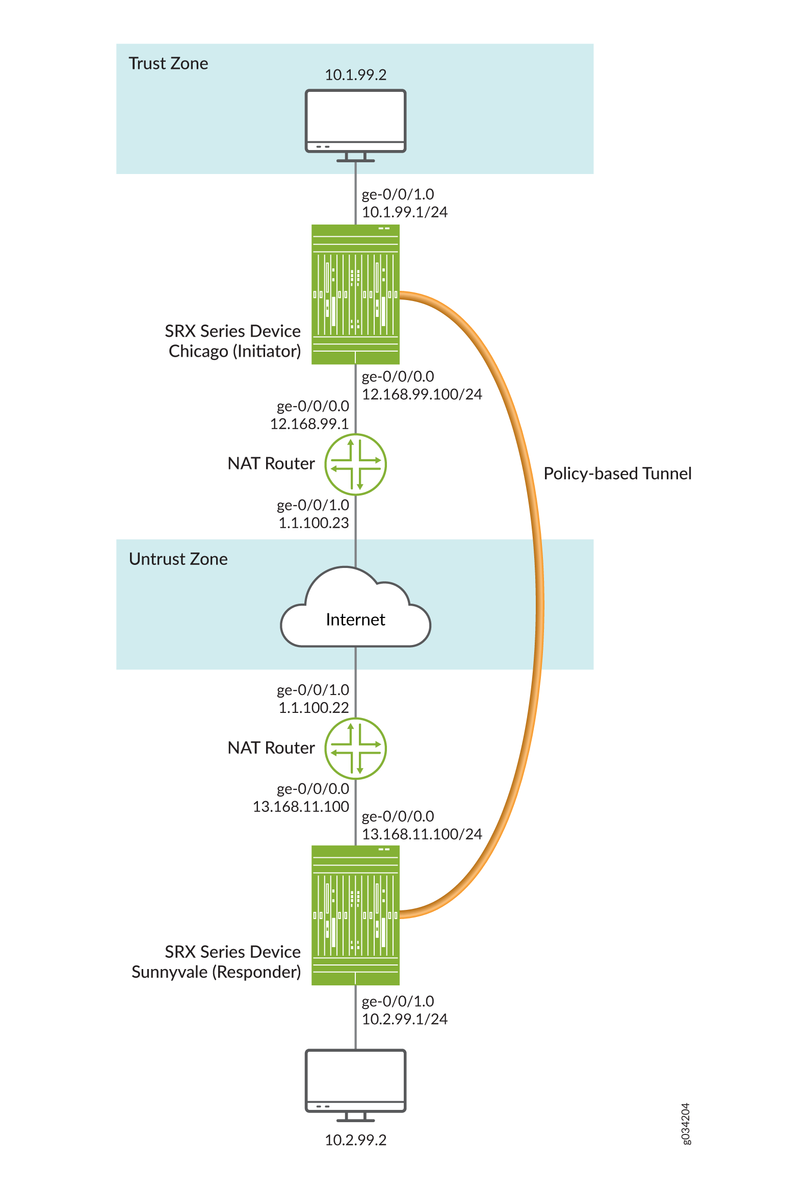
この例では、インターフェイス、IPv4 デフォルト ルート、およびセキュリティ ゾーンを設定します。次に、ローカルピアとリモートピアを含むIKEフェーズ1、IPsecフェーズ2、セキュリティポリシーを設定します。なお、上記の例では、レスポンダーのプライベート IP アドレス 13.168.11.1 は静的 NAT デバイスによって非表示にされ、パブリック IP アドレス 1.1.100.1 にマップされています。
例でイニシエーターに使用される特定の設定パラメーターについては、 表7 から 表10 を参照してください。
機能 |
名前 |
設定パラメータ |
|---|---|---|
インターフェイス |
ge-0/0/0 |
12.168.99.100/24 |
ge-0/0/1 |
10.1.99.1/24 |
|
スタティックルート |
10.2.99.0/24(デフォルトルート) |
ネクスト ホップは 12.168.99.100 です。 |
1.1.100.0/24 |
12.168.99.100 |
|
セキュリティゾーン |
信頼 |
|
信頼できない |
|
機能 |
名前 |
設定パラメータ |
|---|---|---|
プロポーザル |
ike_prop |
|
ポリシー |
ike_pol |
|
ゲートウェイ |
ゲート |
|
機能 |
名前 |
設定パラメータ |
|---|---|---|
プロポーザル |
ipsec_prop |
|
ポリシー |
ipsec_pol |
|
VPN |
first_vpn |
|
目的 |
名前 |
設定パラメータ |
|---|---|---|
セキュリティポリシーは、trustゾーンからuntrustゾーンへのトンネルトラフィックを許可します。 |
POL1 |
|
セキュリティポリシーは、untrustゾーンからtrustゾーンへのトンネルトラフィックを許可します。 |
POL1 |
|
例でレスポンダに使用される特定の設定パラメータについては、 表11 から 表14 を参照してください。
機能 |
名前 |
設定パラメータ |
|---|---|---|
インターフェイス |
ge-0/0/0 |
13.168.11.100/24 |
ge-0/0/1 |
10.2.99.1/24 |
|
スタティックルート |
10.1.99.0/24(デフォルトルート) |
ネクスト ホップは 13.168.11.100 です |
1.1.100.0/24 |
13.168.11.100 |
|
セキュリティゾーン |
信頼 |
|
信頼できない |
|
機能 |
名前 |
設定パラメータ |
|---|---|---|
プロポーザル |
ike_prop |
|
ポリシー |
ike_pol |
|
ゲートウェイ |
ゲート |
|
機能 |
名前 |
設定パラメータ |
|---|---|---|
プロポーザル |
ipsec_prop |
|
ポリシー |
ipsec_pol |
|
VPN |
first_vpn |
|
目的 |
名前 |
設定パラメータ |
|---|---|---|
セキュリティポリシーは、trustゾーンからuntrustゾーンへのトンネルトラフィックを許可します。 |
POL1 |
|
セキュリティポリシーは、untrustゾーンからtrustゾーンへのトンネルトラフィックを許可します。 |
POL1 |
|
設定
- イニシエーターのインターフェイス、ルーティング オプション、およびセキュリティ ゾーンの設定
- イニシエーターの IKE の設定
- イニシエーターのIPsecの設定
- イニシエーターのセキュリティポリシーの設定
- イニシエーターの NAT の設定
- レスポンダーのインターフェイス、ルーティング オプション、セキュリティ ゾーンの設定
- レスポンダの IKE の設定
- レスポンダのIPsecの設定
- レスポンダのセキュリティポリシーの設定
- レスポンダーの NAT の設定
イニシエーターのインターフェイス、ルーティング オプション、およびセキュリティ ゾーンの設定
CLIクイックコンフィグレーション
この例をすばやく設定するには、以下のコマンドをコピーしてテキスト ファイルに貼り付け、改行を削除し、ネットワーク設定に一致させる必要がある詳細情報を変更し、コマンドを [edit] 階層レベルでCLIにコピー アンド ペーストして、設定モードから commit を入力します。
[edit]
set interfaces ge-0/0/0 unit 0 family inet address 12.168.99.100/24
set interfaces ge-0/0/1 unit 0 family inet address 10.1.99.1/24
set routing-options static route 10.2.99.0/24 next-hop 12.168.99.1
set routing-options static route 1.1.100.0/24 next-hop 12.168.99.1
set security zones security-zone trust host-inbound-traffic system-services all
set security zones security-zone trust host-inbound-traffic protocols all
set security zones security-zone trust interfaces ge-0/0/1.0
set security zones security-zone untrust interfaces ge-0/0/0.0
ステップバイステップの手順
次の例では、設定階層のさまざまなレベルに移動する必要があります。その方法の詳細については、『CLIユーザーガイド』の「構成モードでのCLIエディターの使用」を参照してください。
インターフェイス、静的ルート、セキュリティゾーンを設定するには:
イーサネット インターフェイス情報を設定します。
[edit]
user@host# set interfaces ge-0/0/0 unit 0 family inet address 12.168.99.100/24
user@host# set interfaces ge-0/0/1 unit 0 family inet address 10.1.99.1/24
静的ルート情報を設定します。
[edit]
user@host# set routing-options static route 10.2.99.0/24 next-hop 12.168.99.1
user@host# set routing-options static route 1.1.100.0/24 next-hop 12.168.99.1
trustセキュリティ ゾーンを設定します。
[edit ]
user@host# set security zones security-zone trust host-inbound-traffic protocols all
trustセキュリティゾーンにインターフェイスを割り当てます。
[edit security zones security-zone trust]
user@host# set interfaces ge-0/0/1.0
trust セキュリティ ゾーンのシステム サービスを指定します。
[edit security zones security-zone trust]
user@host# set host-inbound-traffic system-services all
untrustセキュリティゾーンにインターフェイスを割り当てます。
[edit security zones security-zone untrust]
user@host# set interfaces ge-0/0/0.0
結果
設定モードから、 show interfaces、 show routing-options、 show security zones コマンドを入力して設定を確認します。 出力に意図した設定が表示されない場合は、この例の手順を繰り返して設定を修正します。
[edit]
user@host# show interfaces
    ge-0/0/0 {
        unit 0 {
            family inet {
                address 12.168.99.100/24;
            }
        }
    }
    ge-0/0/1 {
        unit 0 {
            family inet {
                address 10.1.99.1/24;
            }
        }
    }
[edit]
user@host# show routing-options
    static {
        route 10.2.99.0/24 next-hop 12.168.99.1;
        route 1.1.100.0/24 next-hop 12.168.99.1;
    }
[edit]
user@host# show security zones
    security-zone trust {
        host-inbound-traffic {
            system-services {
                all;
            }
            protocols {
                all;
            }
        }
        interfaces {
            ge-0/0/1.0;
        }
    }
    security-zone untrust {
        host-inbound-traffic {
        }
        interfaces {
            ge-0/0/0.0;
        }
    }
デバイスの設定が完了したら、設定モードから commit を入力します。
イニシエーターの IKE の設定
CLIクイックコンフィグレーション
この例をすばやく設定するには、以下のコマンドをコピーしてテキスト ファイルに貼り付け、改行を削除し、ネットワーク設定に一致させる必要がある詳細情報を変更し、コマンドを [edit] 階層レベルでCLIにコピー アンド ペーストして、設定モードから commit を入力します。
set security ike proposal ike_prop authentication-method pre-shared-keys
set security ike proposal ike_prop dh-group group2
set security ike proposal ike_prop authentication-algorithm md5
set security ike proposal ike_prop encryption-algorithm 3des-cbc
set security ike policy ike_pol mode aggressive
set security ike policy ike_pol proposals ike_prop
set security ike policy ike_pol pre-shared-key ascii-text "$ABC123”
set security ike gateway gate ike-policy ike_pol
set security ike gateway gate address 13.168.11.100
set security ike gateway gate external-interface ge-0/0/0.0
set security ike gateway gate local-identity hostname chicago
ステップバイステップの手順
次の例では、設定階層のさまざまなレベルに移動する必要があります。その方法の詳細については、『CLIユーザーガイド』の「構成モードでのCLIエディターの使用」を参照してください。
IKEを設定するには:
IKEフェーズ1のプロポーザルを作成します。
[edit security ike]
user@host# edit proposal ike_prop
IKEプロポーザルの認証方法を定義します。
[edit security ike proposal ike_prop]
user@host# set authentication-method pre-shared-keys
IKEプロポーザルのDiffie-Hellmanグループを定義します。
[edit security ike proposal ike_prop]
user@host# set dh-group group2
IKEプロポーザルの認証アルゴリズムを定義します。
[edit security ike proposal ike_prop]
user@host# set authentication-algorithm md5
IKEプロポーザルの暗号化アルゴリズムを定義します。
[edit security ike proposal ike_prop]
user@host# set encryption-algorithm 3des-cbc
IKEフェーズ1ポリシーを作成します。
[edit security ike policy ]
user@host# edit policy ike_pol
IKEフェーズ1ポリシーモードを設定します。
[edit security ike policy ike_pol]
user@host# set mode aggressive
IKEプロポーザルへのリファレンスを指定します。
[edit security ike policy ike_pol]
user@host# set proposals ike_prop
IKEフェーズ1ポリシー認証方法を定義します。
[edit security ike policy ike_pol pre-shared-key]
user@host# set ascii-text "$ABC123”
IKEフェーズ1ゲートウェイを作成し、その外部インターフェイスを定義します。
[edit security ike ]
user@host# set gateway gate external-interface ge-0/0/0.0
IKEフェーズ1ゲートウェイアドレスを作成します。
[edit security ike gateway gate]
set address 13.168.11.100
IKEフェーズ1ポリシーリファレンスを定義します。
[edit security ike gateway gate]
set ike-policy ike_pol
ローカルピアの
local-identityを設定します。[edit security ike gateway gate] user@host# set local-identity hostname chicago
結果
設定モードから、 show security ike コマンドを入力して設定を確認します。出力に意図した設定が表示されない場合は、この例の手順を繰り返して設定を修正します。
[edit]
user@host# show security ike
    proposal ike_prop {
        authentication-method pre-shared-keys;
        dh-group group2;
        authentication-algorithm md5;
        encryption-algorithm 3des-cbc;
    }
    policy ike_pol {
        mode aggressive;
        proposals ike_prop;
        pre-shared-key ascii-text "$ABC123”
    }
    gateway gate {
        ike-policy ike_pol;
        address 13.168.11.100;
        local-identity hostname chicago;
        external-interface ge-0/0/0.0;
    }
デバイスの設定が完了したら、設定モードから commit を入力します。
イニシエーターのIPsecの設定
CLIクイックコンフィグレーション
この例をすばやく設定するには、以下のコマンドをコピーしてテキスト ファイルに貼り付け、改行を削除し、ネットワーク設定に一致させる必要がある詳細情報を変更し、コマンドを [edit] 階層レベルでCLIにコピー アンド ペーストして、設定モードから commit を入力します。
set security ipsec proposal ipsec_prop protocol esp
set security ipsec proposal ipsec_prop authentication-algorithm hmac-md5-96
set security ipsec proposal ipsec_prop encryption-algorithm 3des-cbc
set security ipsec policy ipsec_pol perfect-forward-secrecy keys group1
set security ipsec policy ipsec_pol proposals ipsec_prop
set security ipsec vpn first_vpn ike gateway gate
set security ipsec vpn first_vpn ike ipsec-policy ipsec_pol
set security ipsec vpn first_vpn establish-tunnels immediately
ステップバイステップの手順
次の例では、設定階層のさまざまなレベルに移動する必要があります。その方法の詳細については、『CLIユーザーガイド』の「構成モードでのCLIエディターの使用」を参照してください。
IPsecを設定するには:
IPsecフェーズ2のプロポーザルを作成します。
[edit]
user@host# edit security ipsec proposal ipsec_prop
IPsecフェーズ2のプロポーザルプロトコルを指定します。
[edit security ipsec proposal ipsec_prop]
user@host# set protocol esp
IPsecフェーズ2のプロポーザル認証アルゴリズムを指定します。
[edit security ipsec proposal ipsec_prop]
user@host# set authentication-algorithm hmac-md5-96
IPsecフェーズ2のプロポーザルの暗号化アルゴリズムを指定します。
[edit security ipsec proposal ipsec_prop]
user@host# set encryption-algorithm 3des-cbc
IPsecフェーズ2のプロポーザルのリファレンスを指定します。
[edit security ipsec policy ipsec_pol]
user@host# set proposals ipsec_prop
PFS(完全転送秘密)グループ1を使用するIPsecフェーズ2を指定します。
[edit security ipsec policy ipsec_pol ]
user@host# set perfect-forward-secrecy keys group1
IKEゲートウェイを指定します。
[edit security ipsec]
user@host# set vpn first_vpn ike gateway gate
IPsecフェーズ2ポリシーを指定します。
[edit security ipsec]
user@host# set vpn first_vpn ike ipsec-policy ipsec_pol
結果
設定モードから、 show security ipsec コマンドを入力して設定を確認します。出力に意図した設定が表示されない場合は、この例の手順を繰り返して設定を修正します。
[edit]
user@host# show security ipsec
    proposal ipsec_prop {
        protocol esp;
        authentication-algorithm hmac-md5-96;
        encryption-algorithm 3des-cbc;
    }
    policy ipsec_pol {
        perfect-forward-secrecy {
            keys group1;
        }
        proposals ipsec_prop;
    }
    vpn first_vpn {
        ike {
            gateway gate;
            ipsec-policy ipsec_pol;
        }
        establish-tunnels immediately;
    }
デバイスの設定が完了したら、設定モードから commit を入力します。
イニシエーターのセキュリティポリシーの設定
CLIクイックコンフィグレーション
この例をすばやく設定するには、以下のコマンドをコピーしてテキスト ファイルに貼り付け、改行を削除し、ネットワーク設定に一致させる必要がある詳細情報を変更し、コマンドを [edit] 階層レベルでCLIにコピー アンド ペーストして、設定モードから commit を入力します。
set security policies from-zone trust to-zone untrust policy pol1 match source-address any
set security policies from-zone trust to-zone untrust policy pol1 match destination-address any
set security policies from-zone trust to-zone untrust policy pol1 match application any
set security policies from-zone trust to-zone untrust policy pol1 then permit tunnel ipsec-vpn first_vpn
set security policies from-zone untrust to-zone trust policy pol1 match application any
set security policies from-zone untrust to-zone trust policy pol1 then permit tunnel ipsec-vpn first_vpn
ステップバイステップの手順
次の例では、設定階層のさまざまなレベルに移動する必要があります。その方法の詳細については、『CLIユーザーガイド』の「構成モードでのCLIエディターの使用」を参照してください。
セキュリティポリシーを設定するには:
trustゾーンからuntrustゾーンへのトラフィックを許可するセキュリティポリシーを作成します。
[edit security policies from-zone trust to-zone untrust]
user@host# set policy pol1 match source-address any
user@host# set policy pol1 match destination-address any
user@host# set policy pol1 match application any
user@host# set policy pol1 then permit tunnel ipsec-vpn first_vpn
untrust ゾーンから trust ゾーンへのトラフィックを許可するセキュリティ ポリシーを作成します。
[edit security policies from-zone untrust to-zone trust]
user@host# set policy pol1 match application any
user@host# set policy pol1 then permit tunnel ipsec-vpn first_vpn
結果
設定モードから、 show security policies コマンドを入力して設定を確認します。出力に意図した設定が表示されない場合は、この例の手順を繰り返して設定を修正します。
[edit]
user@host# show security policies
    from-zone trust to-zone untrust {
        policy pol1 {
            match {
                source-address any;
                destination-address any;
                application any;
            }
            then {
                permit {
                    tunnel {
                        ipsec-vpn first_vpn;
                    }
                }
            }
        }
    }
    from-zone untrust to-zone trust {
        policy pol1 {
            match {
                application any;
            }
            then {
                permit {
                    tunnel {
                        ipsec-vpn first_vpn;
                    }
                }
            }
        }
    }
デバイスの設定が完了したら、設定モードから commit を入力します。
イニシエーターの NAT の設定
CLIクイックコンフィグレーション
この例をすばやく設定するには、以下のコマンドをコピーしてテキスト ファイルに貼り付け、改行を削除し、ネットワーク設定に一致させる必要がある詳細情報を変更し、コマンドを [edit] 階層レベルでCLIにコピー アンド ペーストして、設定モードから commit を入力します。
set security nat source rule-set ipsec from zone trust
set security nat source rule-set ipsec to zone untrust
set security nat source rule-set ipsec rule 1 match source-address 0.0.0.0/0
set security nat source rule-set ipsec rule 1 then source-nat interface
set security policies from-zone trust to-zone untrust policy allow-all match source-address any
set security policies from-zone trust to-zone untrust policy allow-all match destination-address any
set security policies from-zone trust to-zone untrust policy allow-all match application any
set security policies from-zone trust to-zone untrust policy allow-all then permit
set security policies from-zone untrust to-zone trust policy allow-all match application any
set security policies from-zone untrust to-zone trust policy allow-all then permit
set security zones security-zone trust host-inbound-traffic system-services all
set security zones security-zone trust host-inbound-traffic protocols all
set security zones security-zone trust interfaces ge-0/0/0.0
set security zones security-zone untrust interfaces ge-0/0/1.0
set interfaces ge-0/0/0 unit 0 family inet address 12.168.99.1/24
set interfaces ge-0/0/1 unit 0 family inet address 1.1.100.23/24
set routing-options static route 0.0.0.0/0 next-hop 1.1.100.22
ステップバイステップの手順
次の例では、設定階層のさまざまなレベルに移動する必要があります。その方法の詳細については、『CLIユーザーガイド』の「構成モードでのCLIエディターの使用」を参照してください。
NATを提供するイニシエーターを設定するには:
インターフェイスを設定します。
[edit interfaces]
user@host# set ge-0/0/0 unit 0 family inet address 12.168.99.1/24
user@host# set ge-0/0/1 unit 0 family inet address 1.1.100.23/24
ゾーンを設定します。
[edit security zones security-zone trust]
user@host# set host-inbound-traffic system-services all
user@host# set host-inbound-traffic protocols all
user@host# set interfaces ge-0/0/0.0
[edit security zones security-zone untrust]
user@host# set interfaces ge-0/0/1.0
NATを設定します。
[edit security nat source rule-set ipsec]
user@host# set from zone trust
user@host# set to zone untrust
user@host# set rule 1 match source-address 0.0.0.0/0
user@host# set rule 1 then source-nat interface
デフォルトのセキュリティポリシーを設定します。
[edit security policies]
user@host# set from-zone trust to-zone untrust policy allow-all match source-address any
user@host# set from-zone trust to-zone untrust policy allow-all match destination-address any
user@host# set from-zone trust to-zone untrust policy allow-all match application any
user@host# set from-zone trust to-zone untrust policy allow-all then permit
user@host# set from-zone untrust to-zone trust policy allow-all match application any
user@host# set from-zone untrust to-zone trust policy allow-all then permit
ルーティングオプションを設定します。
[edit routing-options
user@host# set static route 0.0.0.0/0 next-hop 1.1.100.22
結果
設定モードから、 show security nat コマンドを入力して設定を確認します。出力に意図した設定が表示されない場合は、この例の手順を繰り返して設定を修正します。
[edit]
user@host# show security nat
        source {
            rule-set ipsec {
                from zone trust;
                to zone untrust;
                rule 1 {
                    match {
                        source-address 0.0.0.0/0;
                    }
                    then {
                        source-nat {
                            interface;
                        }
                    }
                }
            }
        }
    }
    policies {
        from-zone trust to-zone untrust {
            policy allow-all {
                match {
                    source-address any;
                    destination-address any;
                    application any;
                }
                then {
                    permit;
                }
            }
        }
        from-zone untrust to-zone trust {
            policy allow-all {
                match {
                    application any;
                }
                then {
                    permit;
                }
            }
        }
    }
    zones {
        security-zone trust {
            host-inbound-traffic {
                system-services {
                    all;
                }
                protocols {
                    all;
                }
            }
            interfaces {
                ge-0/0/0.0;
            }
        }
        security-zone untrust {
            host-inbound-traffic {
            }
            interfaces {
                ge-0/0/1.0;
            }
        }
    }
}
interfaces {
    ge-0/0/0 {
        unit 0 {
            family inet {
                address 12.168.99.1/24;
            }
        }
    }
    ge-0/0/1 {
        unit 0 {
            family inet {
                address 1.1.100.23/24;
            }
        }
    }
}
routing-options {
    static {
        route 0.0.0.0/0 next-hop 1.1.100.22;
    }
デバイスの設定が完了したら、設定モードから commit を入力します。
レスポンダーのインターフェイス、ルーティング オプション、セキュリティ ゾーンの設定
CLIクイックコンフィグレーション
この例をすばやく設定するには、以下のコマンドをコピーしてテキスト ファイルに貼り付け、改行を削除し、ネットワーク設定に一致させる必要がある詳細情報を変更し、コマンドを [edit] 階層レベルでCLIにコピー アンド ペーストして、設定モードから commit を入力します。
set interfaces ge-0/0/0 unit 0 family inet address 13.168.11.100/24
set interfaces ge-0/0/1 unit 0 family inet address 10.2.99.1/24
set routing-options static route 10.1.99.0/24 next-hop 13.168.11.1
set routing-options static route 1.1.100.0/24 next-hop 13.168.11.1
set security zones security-zone untrust interfaces ge-0/0/0.0
set security zones security-zone trust host-inbound-traffic system-services all
set security zones security-zone trust host-inbound-traffic protocols all
set security zones security-zone trust interfaces ge-0/0/1.0
ステップバイステップの手順
次の例では、設定階層のさまざまなレベルに移動する必要があります。その方法の詳細については、『CLIユーザーガイド』の「構成モードでのCLIエディターの使用」を参照してください。
インターフェイス、静的ルート、セキュリティゾーン、セキュリティポリシーを設定するには:
イーサネット インターフェイス情報を設定します。
[edit]
user@host# set interfaces ge-0/0/0 unit 0 family inet address 13.168.11.100/24
user@host# set interfaces ge-0/0/1 unit 0 family inet address 10.2.99.1/24
静的ルート情報を設定します。
[edit]
user@host# set routing-options static route 10.1.99.0/24 next-hop 13.168.11.1
user@host# set routing-options static route 1.1.100.0/24 next-hop 13.168.11.1
untrustセキュリティゾーンにインターフェイスを割り当てます。
[edit security zones security-zone untrust]
user@host# set interfaces ge-0/0/0.0
trustセキュリティ ゾーンを設定します。
[edit]
user@host# set security zones security-zone trust host-inbound-traffic protocols all
trustセキュリティゾーンにインターフェイスを割り当てます。
[edit security zones security-zone trust]
user@host# set interfaces ge-0/0/1.0
trust セキュリティ ゾーンで許可されたシステム サービスを指定します。
[edit security zones security-zone trust]
user@host# set host-inbound-traffic system-services all
結果
設定モードから、 show interfaces、 show routing-options、 show security zones コマンドを入力して設定を確認します。出力に意図した設定が表示されない場合は、この例の手順を繰り返して設定を修正します。
[edit]
user@host# show interfaces
    ge-0/0/0 {
        unit 0 {
            family inet {
                address 13.168.11.100/24;
            }
        }
    }
    ge-0/0/1 {
        unit 0 {
            family inet {
                address 10.2.99.1/24;
            }
        }
    }
[edit]
user@host# show routing-options
    static {
        route 10.1.99.0/24 next-hop 13.168.11.1;
        route 1.1.100.0/24 next-hop 13.168.11.1;
    }
[edit]
user@host# show security zones
    security-zone untrust {
        host-inbound-traffic {
        }
        interfaces {
            ge-0/0/0.0;
        }
    }
    security-zone trust {
        host-inbound-traffic {
            system-services {
                all;
            }
            protocols {
                all;
            }
        }
        interfaces {
            ge-0/0/1.0;
        }
    }
デバイスの設定が完了したら、設定モードから commit を入力します。
レスポンダの IKE の設定
CLIクイックコンフィグレーション
この例をすばやく設定するには、以下のコマンドをコピーしてテキスト ファイルに貼り付け、改行を削除し、ネットワーク設定に一致させる必要がある詳細情報を変更し、コマンドを [edit] 階層レベルでCLIにコピー アンド ペーストして、設定モードから commit を入力します。
set security ike proposal ike_prop authentication-method pre-shared-keys
set security ike proposal ike_prop dh-group group2
set security ike proposal ike_prop authentication-algorithm md5
set security ike proposal ike_prop encryption-algorithm 3des-cbc
set security ike policy ike_pol mode aggressive
set security ike policy ike_pol proposals ike_prop
set security ike policy ike_pol pre-shared-key ascii-text "$ABC123"
set security ike gateway gate ike-policy ike_pol
set security ike gateway gate dynamic hostname chicago
set security ike gateway gate external-interface ge-0/0/0.0
ステップバイステップの手順
次の例では、設定階層のさまざまなレベルに移動する必要があります。その方法の詳細については、『CLIユーザーガイド』の「構成モードでのCLIエディターの使用」を参照してください。
IKEを設定するには:
IKEプロポーザルの認証方法を定義します。
[edit security ike proposal ike_prop]
user@host# set authentication-method pre-shared-key
IKEプロポーザルのDiffie-Hellmanグループを定義します。
[edit security ike proposal ike_prop]
user@host# set dh-group group2
IKEプロポーザルの認証アルゴリズムを定義します。
[edit security ike proposal ike_prop]
user@host# set authentication-algorithm md5
IKEプロポーザルの暗号化アルゴリズムを定義します。
[edit security ike proposal ike_prop]
user@host# set encryption-algorithm 3des-cbc
IKEフェーズ1ポリシーを作成します。
[edit security ike]
user@host# edit policy ike_pol
IKEフェーズ1ポリシーモードを設定します。
[edit security ike policy ike_pol]
user@host# set mode aggressive
IKEプロポーザルへのリファレンスを指定します。
[edit security ike policy ike_pol]
user@host# set proposals ike_prop
IKEフェーズ1ポリシー認証方法を定義します。
[edit security ike policy ike_pol]
user@host# set pre-shared-key ascii-text "$ABC123"
IKEフェーズ1ゲートウェイを作成し、その動的ホスト名を定義します。
[edit security ike gateway gate]
user@host# set dynamic hostname chicago
IKEフェーズ1ゲートウェイを作成し、その外部インターフェイスを定義します。
[edit security ike gateway gate]
user@host# set external-interface ge-0/0/0.0
IKEフェーズ1ポリシーリファレンスを定義します。
[edit security ike gateway gate]
user@host# set ike-policy ike_pol
結果
設定モードから、 show security ike コマンドを入力して設定を確認します。出力に意図した設定が表示されない場合は、この例の手順を繰り返して設定を修正します。
[edit]
user@host# show security ike
    proposal ike_prop {
        authentication-method pre-shared-keys;
        dh-group group2;
        authentication-algorithm md5;
        encryption-algorithm 3des-cbc;
    }
    policy ike_pol {
        mode aggressive;
        proposals ike_prop;
        pre-shared-key ascii-text "$ABC123";
    }
    gateway gate {
        ike-policy ike_pol;
        dynamic hostname chicago;
        external-interface ge-0/0/0.0;
    }
デバイスの設定が完了したら、設定モードから commit を入力します。
レスポンダのIPsecの設定
CLIクイックコンフィグレーション
この例をすばやく設定するには、以下のコマンドをコピーしてテキスト ファイルに貼り付け、改行を削除し、ネットワーク設定に一致させる必要がある詳細情報を変更し、コマンドを [edit] 階層レベルでCLIにコピー アンド ペーストして、設定モードから commit を入力します。
set security ipsec proposal ipsec_prop protocol esp
set security ipsec proposal ipsec_prop authentication-algorithm hmac-md5-96
set security ipsec proposal ipsec_prop encryption-algorithm 3des-cbc
set security ipsec policy ipsec_pol perfect-forward-secrecy keys group1
set security ipsec policy ipsec_pol proposals ipsec_prop
set security ipsec vpn first_vpn ike gateway gate
set security ipsec vpn first_vpn ike ipsec-policy ipsec_pol
ステップバイステップの手順
次の例では、設定階層のさまざまなレベルに移動する必要があります。その方法の詳細については、『CLIユーザーガイド』の「構成モードでのCLIエディターの使用」を参照してください。
IPsecを設定するには:
IPsecフェーズ2のプロポーザルを作成します。
[edit]
user@host# edit security ipsec proposal ipsec_prop
IPsecフェーズ2のプロポーザルプロトコルを指定します。
[edit security security ipsec proposal ipsec_prop]
user@host# set protocol esp
IPsecフェーズ2のプロポーザル認証アルゴリズムを指定します。
[edit security ipsec proposal ipsec_prop]
user@host# set authentication-algorithm hmac-md5-96
IPsecフェーズ2のプロポーザルの暗号化アルゴリズムを指定します。
[edit security ipsec proposal ipsec_prop]
user@host# set encryption-algorithm 3des-cbc
IPsecフェーズ2のポリシーを作成します。
[edit security ipsec]
user@host# edit policy ipsec_pol
Perfect Forward Secrecy(PFS)グループ1を使用するようにIPsecフェーズ2を設定します。
[edit security ipsec policy ipsec_pol]
user@host# set perfect-forward-secrecy keys group1
IPsecフェーズ2のプロポーザルのリファレンスを指定します。
[edit security ipsec policy ipsec_pol]
user@host# set proposals ipsec_prop
IKEゲートウェイを指定します。
[edit security ipsec]
user@host# set vpn first_vpn ike gateway gate
IPsecフェーズ2ポリシーを指定します。
[edit security ipsec]
user@host# set vpn first_vpn ike ipsec-policy ipsec_pol
結果
設定モードから、 show security ipsec コマンドを入力して設定を確認します。出力に意図した設定が表示されない場合は、この例の手順を繰り返して設定を修正します。
[edit]
user@host# show security ipsec
    proposal ipsec_prop {
        protocol esp;
        authentication-algorithm hmac-md5-96;
        encryption-algorithm 3des-cbc;
    }
    policy ipsec_pol {
        perfect-forward-secrecy {
            keys group1;
        }
        proposals ipsec_prop;
    }
    vpn first_vpn {
        ike {
            gateway gate;
            ipsec-policy ipsec_pol;
        }
    }
デバイスの設定が完了したら、設定モードから commit を入力します。
レスポンダのセキュリティポリシーの設定
CLIクイックコンフィグレーション
この例をすばやく設定するには、以下のコマンドをコピーしてテキスト ファイルに貼り付け、改行を削除し、ネットワーク設定に一致させる必要がある詳細情報を変更し、コマンドを [edit] 階層レベルでCLIにコピー アンド ペーストして、設定モードから commit を入力します。
set security policies from-zone trust to-zone untrust policy pol1 match source-address any
set security policies from-zone trust to-zone untrust policy pol1 match destination-address any
set security policies from-zone trust to-zone untrust policy pol1 match application any
set security policies from-zone trust to-zone untrust policy pol1 then permit tunnel ipsec-vpn first_vpn
set security policies from-zone untrust to-zone trust policy pol1 match application any
set security policies from-zone untrust to-zone trust policy pol1 then permit tunnel ipsec-vpn first_vpn
ステップバイステップの手順
次の例では、設定階層のさまざまなレベルに移動する必要があります。その方法の詳細については、『CLIユーザーガイド』の「構成モードでのCLIエディターの使用」を参照してください。
セキュリティポリシーを設定するには:
trustゾーンからuntrustゾーンへのトラフィックを許可するセキュリティポリシーを作成します。
[edit security policies from-zone trust to-zone untrust]
user@host# set policy pol1 match source-address any
user@host# set policy pol1 match destination-address any
user@host# set policy pol1 match application any
user@host# set policy pol1 then permit tunnel ipsec-vpn first_vpn
untrust ゾーンから trust ゾーンへのトラフィックを許可するセキュリティ ポリシーを作成します。
[edit security policies from-zone untrust to-zone trust]
user@host# set policy pol1 match application any
user@host# set policy pol1 then permit tunnel ipsec-vpn first_vpn
結果
設定モードから、 show security policies コマンドを入力して設定を確認します。出力に意図した設定が表示されない場合は、この例の手順を繰り返して設定を修正します。
[edit]
user@host# show security policies
    from-zone trust to-zone untrust {
        policy pol1 {
            match {
                source-address any;
                destination-address any;
                application any;
            }
            then {
                permit {
                    tunnel {
                        ipsec-vpn first_vpn;
                    }
                }
            }
        }
    }
    from-zone untrust to-zone trust {
        policy pol1 {
            match {
                application any;
            }
            then {
                permit {
                    tunnel {
                        ipsec-vpn first_vpn;
                    }
                }
            }
        }
    }
デバイスの設定が完了したら、設定モードから commit を入力します。
レスポンダーの NAT の設定
CLIクイックコンフィグレーション
この例をすばやく設定するには、以下のコマンドをコピーしてテキスト ファイルに貼り付け、改行を削除し、ネットワーク設定に一致させる必要がある詳細情報を変更し、コマンドを [edit] 階層レベルでCLIにコピー アンド ペーストして、設定モードから commit を入力します。
set security nat source rule-set ipsec from zone trust
set security nat source rule-set ipsec to zone untrust
set security nat source rule-set ipsec rule 1 match source-address 0.0.0.0/0
set security nat source rule-set ipsec rule 1 then source-nat interface
set security policies from-zone trust to-zone untrust policy allow-all match source-address any
set security policies from-zone trust to-zone untrust policy allow-all match destination-address any
set security policies from-zone trust to-zone untrust policy allow-all match application any
set security policies from-zone trust to-zone untrust policy allow-all then permit
set security policies from-zone untrust to-zone trust policy allow-all match application any
set security policies from-zone untrust to-zone trust policy allow-all then permit
set security zones security-zone trust host-inbound-traffic system-services all
set security zones security-zone trust host-inbound-traffic protocols all
set security zones security-zone trust interfaces ge-0/0/0.0
set security zones security-zone untrust interfaces ge-0/0/1.0
set interfaces ge-0/0/0 unit 0 family inet address 13.168.11.1/24
set interfaces ge-0/0/1 unit 0 family inet address 1.1.100.22/24
set routing-options static route 0.0.0.0/0 next-hop 1.1.100.23
ステップバイステップの手順
次の例では、設定階層のさまざまなレベルに移動する必要があります。その方法の詳細については、『CLIユーザーガイド』の「構成モードでのCLIエディターの使用」を参照してください。
NAT を提供するレスポンダを設定するには:
インターフェイスを設定します。
[edit interfaces]
user@host# set ge-0/0/0 unit 0 family inet address 13.168.11.1/24
user@host# set ge-0/0/1 unit 0 family inet address 1.1.100.22/24
ゾーンを設定します。
[edit security zones security-zone trust]
user@host# set host-inbound-traffic system-services all
user@host# set host-inbound-traffic protocols all
user@host# set interfaces ge-0/0/0.0
[edit security zones security-zone untrust]
user@host# set interfaces ge-0/0/1.0
NATを設定します。
[edit security nat source rule-set ipsec]
user@host# set from zone trust
user@host# set to zone untrust
user@host# set rule 1 match source-address 0.0.0.0/0
user@host# set rule 1 then source-nat interface
デフォルトのセキュリティポリシーを設定します。
[edit security policies]
user@host# set from-zone trust to-zone untrust policy allow-all match source-address any
user@host# set from-zone trust to-zone untrust policy allow-all match destination-address any
user@host# set from-zone trust to-zone untrust policy allow-all match application any
user@host# set from-zone trust to-zone untrust policy allow-all then permit
user@host# set from-zone untrust to-zone trust policy allow-all match application any
user@host# set from-zone untrust to-zone trust policy allow-all then permit
ルーティングオプションを設定します。
[edit routing-options
user@host# set static route 0.0.0.0/0 next-hop 1.1.100.23
結果
設定モードから、 show security nat コマンドを入力して設定を確認します。出力に意図した設定が表示されない場合は、この例の手順を繰り返して設定を修正します。
[edit]
user@host# show security nat
    nat {
        source {
            rule-set ipsec {
                from zone trust;
                to zone untrust;
                rule 1 {
                    match {
                        source-address 0.0.0.0/0;
                    }
                    then {
                        source-nat {
                            interface;
                        }
                    }
                }
            }
        }
    }
    policies {
        from-zone trust to-zone untrust {
            policy allow-all {
                match {
                    source-address any;
                    destination-address any;
                    application any;
                }
                then {
                    permit;
                }
            }
        }
        from-zone untrust to-zone trust {
            policy allow-all {
                match {
                    application any;
                }
                then {
                    permit;
                }
            }
        }
    }
    zones {
        security-zone trust {
            host-inbound-traffic {
                system-services {
                    all;
                }
                protocols {
                    all;
                }
            }
            interfaces {
                ge-0/0/0.0;
            }
        }
        security-zone untrust {
            host-inbound-traffic {
            }
            interfaces {
                ge-0/0/1.0;
            }
        }
    }
}
interfaces {
    ge-0/0/0 {
        unit 0 {
            family inet {
                address 13.168.11.1/24;
            }
        }
    }
    ge-0/0/1 {
        unit 0 {
            family inet {
                address 1.1.100.22/24;
            }
        }
    }
}
routing-options {
    static {
        route 0.0.0.0/0 next-hop 1.1.100.23;
    }
デバイスの設定が完了したら、設定モードから commit を入力します。
検証
設定が正常に機能していることを確認するには、以下のタスクを実行します。
- イニシエーターの IKE フェーズ 1 ステータスの確認
- イニシエーターのIPsecセキュリティ関連付けの確認
- レスポンダーの IKE フェーズ 1 ステータスの確認
- レスポンダーのIPsecセキュリティ関連付けの確認
イニシエーターの IKE フェーズ 1 ステータスの確認
目的
IKEフェーズ1ステータスを確認します。
アクション
検証プロセスを開始する前に、10.1.99.0ネットワーク内のホストから10.2.99.0ネットワーク内のホストにトラフィックを送信する必要があります。ルートベースVPNの場合、ファイアウォールはトンネルを介してトラフィックを開始します。IPsecトンネルをテストする場合は、VPNの片側にある別のデバイスからVPNの反対側にある第2デバイスにテストトラフィックを送信することをお勧めします。例えば、10.1.99.2 から 10.2.99.2 に ping 操作を開始します。
動作モードから、 show security ike security-associations コマンドを入力します。コマンドからインデックス番号を取得した後、 show security ike security-associations index index_number detail コマンドを使用します。
user@host> show security ike security-associations
Index   State  Initiator cookie  Responder cookie  Mode           Remote Address
5649304 UP     c3193077d38e426f  011f0ef28d928f4c  Aggressive     13.168.11.
user@host> show security ike security-associations index 5649304 detail
IKE peer 13.168.11.100, Index 5649304, Gateway Name: gate
  Role: Initiator, State: UP
  Initiator cookie: c3193077d38e426f, Responder cookie: 011f0ef28d928f4c
  Exchange type: Aggressive, Authentication method: Pre-shared-keys
  Local: 12.168.99.100:4500, Remote: 13.168.11.100:4500
  Lifetime: Expires in 26359 seconds
  Reauth Lifetime: Disabled
  IKE Fragmentation: Disabled, Size: 0
  Remote Access Client Info: Unknown Client
  Peer ike-id: 13.168.11.100
  AAA assigned IP: 0.0.0.0
  Algorithms:
   Authentication        : hmac-md5-96
   Encryption            : 3des-cbc
   Pseudo random function: hmac-md5
   Diffie-Hellman group  : DH-group-2
  Traffic statistics:
   Input  bytes  :                 1140
   Output bytes  :                 1203
   Input  packets:                    6
   Output packets:                    6
   Input  fragmentated packets:       0
   Output fragmentated packets:       0
  IPSec security associations: 2 created, 3 deleted
  Phase 2 negotiations in progress: 1

    Negotiation type: Quick mode, Role: Initiator, Message ID: 0
    Local: 12.168.99.100:4500, Remote: 13.168.11.100:4500
    Local identity: chicago
    Remote identity: 13.168.11.100
    Flags: IKE SA is created
意味
show security ike security-associationsコマンドは、すべてのアクティブなIKEフェーズ1のSAを一覧表示します。SAが表示されない場合は、フェーズ1の確立に問題があったことを示しています。設定でIKEポリシーパラメータと外部インターフェイスの設定を確認してください。
SAが表示される場合は、以下の情報を確認します。
インデックス—この値はIKE SAごとに固有で、
show security ike security-associations index detailコマンドで使用すると、SAに関する詳細情報を得ることができます。リモートアドレス—リモートIPアドレスが正しく、ポート4500がピアツーピア通信に使用されていることを確認します。
ロールイニシエータの状態
Up:フェーズ1SAが確立されました。
Down - フェーズ 1 SA の確立に問題がありました。
IPsec SAペアの両方のピアがポート4500を使用しています。これはNAT-Tが実装されたことを示しています。(NAT-T は、ポート 4500 またはその他のランダムな大きな番号のポートを使用します)。
ピア IKE ID—リモート(レスポンダー)ID が正しいことを確認します。この例のホスト名はsunnyvaleです。
ローカルIDとリモートID—これらが正しいことを確認します。
モード—正しいモードが使用されていることを確認します。
設定で以下が適切か検証します。
外部インターフェイス(インターフェイスはIKEパケットを受信するインターフェイスである必要があります)
IKEポリシーパラメータ
事前共有鍵情報
フェーズ1のプロポーザルパラメーター(両方のピアで一致する必要があります)
show security ike security-associationsコマンドは、セキュリティアソシエーションに関する以下の追加情報を一覧表示します。
使用される認証および暗号化アルゴリズム
フェーズ1のライフタイム
トラフィック統計情報(トラフィックが双方向に正しく流れていることを検証するために使用できます)
ロール情報
トラブルシューティングは、レスポンダ ロールを使用してピア上で実行するのが最適です。
開始側と応答側の情報
作成されたIPsec SAの数
進行中のフェーズ2ネゴシエーションの数
イニシエーターのIPsecセキュリティ関連付けの確認
目的
IPsecステータスを確認します。
アクション
動作モードから、 show security ipsec security-associations コマンドを入力します。コマンドからインデックス番号を取得した後、 show security ipsec security-associations index index_number detail コマンドを使用します。
user@host> show security ipsec security-associations

Total active tunnels: 1     Total Ipsec sas: 1
  ID    Algorithm       SPI      Life:sec/kb  Mon lsys Port  Gateway
  <2      ESP:3des/md5    aff3ac30 1103/ unlim  -   root 4500  13.168.11.100
  >2      ESP:3des/md5    40539d12 1103/ unlim  -   root 4500  13.168.11.100
user@host> show security ipsec security-associations detail

ID: 2 Virtual-system: root, VPN Name: first_vpn
  Local Gateway: 12.168.99.100, Remote Gateway: 13.168.11.100
  Local Identity: ipv4_subnet(any:0,[0..7]=0.0.0.0/0)
  Remote Identity: ipv4_subnet(any:0,[0..7]=0.0.0.0/0)
  Version: IKEv1
  DF-bit: clear, Copy-Outer-DSCP Disabled                             , Policy-name: pol1
  Port: 4500, Nego#: 7, Fail#: 0, Def-Del#: 0 Flag: 0x600829
  Multi-sa, Configured SAs# 1, Negotiated SAs#: 1
  Tunnel events:
    Wed Apr 08 2020 19:13:53: IPSec SA negotiation successfully completed (1 times)
    Wed Apr 08 2020
    : IPSec SA delete payload received from peer, corresponding IPSec SAs cleared (1 times)
    Wed Apr 08 2020 19:13:09: IPSec SA negotiation successfully completed (1 times)
    Wed Apr 08 2020 19:13:09: User cleared IPSec SA from CLI (1 times)
    Wed Apr 08 2020 19:13:09: IKE SA negotiation successfully completed (5 times)
    Wed Apr 08 2020 19:12:18: IPSec SA negotiation successfully completed (1 times)
    Wed Apr 08 2020 19:12:18: User cleared IPSec SA from CLI (1 times)
    Wed Apr 08 2020 19:12:12: IPSec SA negotiation successfully completed (1 times)
    Wed Apr 08 2020 19:12:12: User cleared IPSec SA from CLI (1 times)
    Wed Apr 08 2020 19:06:52: Peer's IKE-ID validation failed during negotiation (2 times)
    Wed Apr 08 2020
    : Negotiation failed  with error code NO_PROPOSAL_CHOSEN received from peer (2 times)
    Wed Apr 08 2020 19:05:26: Peer's IKE-ID validation failed during negotiation (1 times)
    Wed Apr 08 2020
    : Negotiation failed  with error code NO_PROPOSAL_CHOSEN received from peer (1 times)
    Wed Apr 08 2020 19:04:26: Peer's IKE-ID validation failed during negotiation (1 times)
    Wed Apr 08 2020
    : Negotiation failed  with error code NO_PROPOSAL_CHOSEN received from peer (1 times)
    Wed Apr 08 2020 19:03:26: Peer's IKE-ID validation failed during negotiation (1 times)
  Direction: inbound, SPI: aff3ac30, AUX-SPI: 0
                              , VPN Monitoring: -
    Hard lifetime: Expires in 1093 seconds
    Lifesize Remaining:  Unlimited
    Soft lifetime: Expires in 453 seconds
    Mode: Tunnel(0 0), Type: dynamic, State: installed
    Protocol: ESP, Authentication: hmac-md5-96, Encryption: 3des-cbc
    Anti-replay service: counter-based enabled, Replay window size: 64
  Direction: outbound, SPI: 40539d12, AUX-SPI: 0
                              , VPN Monitoring: -
    Hard lifetime: Expires in 1093 seconds
    Lifesize Remaining:  Unlimited
    Soft lifetime: Expires in 453 seconds
    Mode: Tunnel(0 0), Type: dynamic, State: installed
    Protocol: ESP, Authentication: hmac-md5-96, Encryption: 3des-cbc
    Anti-replay service: counter-based enabled, Replay window size: 64
意味
show security ipsec security-associationsコマンドからの出力には、以下の情報が表示されます。
リモートゲートウェイのNATアドレスは13.168.11.100です。
IPsec SAペアの両方のピアがポート4500を使用しています。これはNAT-Tが実装されたことを示しています。(NAT-T は、ポート 4500 またはその他のランダムな大きな番号のポートを使用します)。
両方向のSPI、ライフタイム(秒)、使用制限(またはKBで示したライフサイズ)が表示されます。3390/ unlimited という値は、フェーズ2のライフタイムの有効期限は3390秒であり、ライフサイズは指定されていないため、無制限であることを示しています。フェーズ2のライフタイムはフェーズ1のライフタイムと異なる場合があります。これはVPNが起動した後にフェーズ2はフェーズ1に依存しないためです。
月曜の列にあるハイフンで示されているように、このSAではVPN監視が有効になっていません。VPN監視が有効な場合、Uは監視が稼働していることを示し、Dは監視が停止していることを示します。
仮想システム(vsys)はルート システムであり、常に 0 が表示されます。
レスポンダーの IKE フェーズ 1 ステータスの確認
目的
IKEフェーズ1ステータスを確認します。
アクション
動作モードから、 show security ike security-associations コマンドを入力します。コマンドからインデックス番号を取得した後、 show security ike security-associations index index_number detail コマンドを使用します。
user@host> show security ike security-associations

Index   State  Initiator cookie  Responder cookie  Mode           Remote Address
2914355 UP     c3193077d38e426f  011f0ef28d928f4c  Aggressive     1.1.100.23
user@host> show security ike security-associations index 2914355 detail

  IKE peer 1.1.100.23, Index 2914355, Gateway Name: gate
  Role: Responder, State: UP
  Initiator cookie: c3193077d38e426f, Responder cookie: 011f0ef28d928f4c
  Exchange type: Aggressive, Authentication method: Pre-shared-keys
  Local: 13.168.11.100:4500, Remote: 1.1.100.23:23434
  Lifetime: Expires in 26137 seconds
  Reauth Lifetime: Disabled
  IKE Fragmentation: Disabled, Size: 0
  Remote Access Client Info: Unknown Client
  Peer ike-id: chicago
  AAA assigned IP: 0.0.0.0
  Algorithms:
   Authentication        : hmac-md5-96
   Encryption            : 3des-cbc
   Pseudo random function: hmac-md5
   Diffie-Hellman group  : DH-group-2
  Traffic statistics:
   Input  bytes  :                 1203
   Output bytes  :                 1140
   Input  packets:                    6
   Output packets:                    6
   Input  fragmentated packets:       0
   Output fragmentated packets:       0
  IPSec security associations: 2 created, 0 deleted
  Phase 2 negotiations in progress: 1

    Negotiation type: Quick mode, Role: Responder, Message ID: 0
    Local: 13.168.11.100:4500, Remote: 1.1.100.23:23434
    Local identity: 13.168.11.100
    Remote identity: chicago
    Flags: IKE SA is created
意味
show security ike security-associationsコマンドは、すべてのアクティブなIKEフェーズ1のSAを一覧表示します。SAが表示されない場合は、フェーズ1の確立に問題があったことを示しています。設定でIKEポリシーパラメータと外部インターフェイスの設定を確認してください。
SAが表示される場合は、以下の情報を確認します。
インデックス—この値はIKE SAごとに固有で、
show security ike security-associations index detailコマンドで使用すると、SAに関する詳細情報を得ることができます。リモートアドレス—リモートIPアドレスが正しく、ポート4500がピアツーピア通信に使用されていることを確認します。
ロールレスポンダーの状態
Up:フェーズ1SAが確立されました。
Down - フェーズ 1 SA の確立に問題がありました。
ピア IKE ID - ピアのローカル ID が正しいことを確認します。この例のホスト名はchicagoです。
ローカルIDとリモートID—これらが正しいことを確認します。
モード—正しいモードが使用されていることを確認します。
設定で以下が適切か検証します。
外部インターフェイス(インターフェイスはIKEパケットを受信するインターフェイスである必要があります)
IKEポリシーパラメータ
事前共有鍵情報
フェーズ1のプロポーザルパラメーター(両方のピアで一致する必要があります)
show security ike security-associationsコマンドは、セキュリティアソシエーションに関する以下の追加情報を一覧表示します。
使用される認証および暗号化アルゴリズム
フェーズ1のライフタイム
トラフィック統計情報(トラフィックが双方向に正しく流れていることを検証するために使用できます)
ロール情報
トラブルシューティングは、レスポンダ ロールを使用してピア上で実行するのが最適です。
開始側と応答側の情報
作成されたIPsec SAの数
進行中のフェーズ2ネゴシエーションの数
レスポンダーのIPsecセキュリティ関連付けの確認
目的
IPsecステータスを確認します。
アクション
動作モードから、 show security ipsec security-associations コマンドを入力します。コマンドからインデックス番号を取得した後、 show security ipsec security-associations index index_number detail コマンドを使用します。
user@host> show security ipsec security-associations

Total active tunnels: 1     Total Ipsec sas: 1
  ID    Algorithm       SPI      Life:sec/kb  Mon lsys Port  Gateway
  <67108878 ESP:3des/md5  40539d12 939/ unlim   -   root 23434 1.1.100.23
  >67108878 ESP:3des/md5  aff3ac30 939/ unlim   -   root 23434 1.1.100.23
user@host> show security ipsec security-associations detail

  ID: 67108878 Virtual-system: root, VPN Name: first_vpn
  Local Gateway: 13.168.11.100, Remote Gateway: 1.1.100.23
  Local Identity: ipv4_subnet(any:0,[0..7]=0.0.0.0/0)
  Remote Identity: ipv4_subnet(any:0,[0..7]=0.0.0.0/0)
  Version: IKEv1
  DF-bit: clear, Copy-Outer-DSCP Disabled                             , Policy-name: pol1
  Port: 23434, Nego#: 8, Fail#: 0, Def-Del#: 0 Flag: 0x608829
  Multi-sa, Configured SAs# 1, Negotiated SAs#: 1
  Tunnel events:
    Wed Apr 08 2020 19:14:22: IPSec SA negotiation successfully completed (1 times)
    Wed Apr 08 2020 19:14:15: User cleared IPSec SA from CLI (1 times)
    Wed Apr 08 2020 19:13:39: IPSec SA negotiation successfully completed (3 times)
    Wed Apr 08 2020 19:13:39: IKE SA negotiation successfully completed (4 times)
    Wed Apr 08 2020
    : IPSec SA delete payload received from peer, corresponding IPSec SAs cleared (1 times)
    Wed Apr 08 2020 19:10:39: IPSec SA negotiation successfully completed (1 times)
    Wed Apr 08 2020 19:10:20: User cleared IPSec SA from CLI (1 times)
    Wed Apr 08 2020 19:10:08: IPSec SA negotiation successfully completed (1 times)
    Wed Apr 08 2020
    : Tunnel is ready. Waiting for trigger event or peer to trigger negotiation (1 times)
  Direction: inbound, SPI: 40539d12, AUX-SPI: 0
                              , VPN Monitoring: -
    Hard lifetime: Expires in 930 seconds
    Lifesize Remaining:  Unlimited
    Soft lifetime: Expires in 335 seconds
    Mode: Tunnel(0 0), Type: dynamic, State: installed
    Protocol: ESP, Authentication: hmac-md5-96, Encryption: 3des-cbc
    Anti-replay service: counter-based enabled, Replay window size: 64
  Direction: outbound, SPI: aff3ac30, AUX-SPI: 0
                              , VPN Monitoring: -
    Hard lifetime: Expires in 930 seconds
    Lifesize Remaining:  Unlimited
    Soft lifetime: Expires in 335 seconds
    Mode: Tunnel(0 0), Type: dynamic, State: installed
    Protocol: ESP, Authentication: hmac-md5-96, Encryption: 3des-cbc
    Anti-replay service: counter-based enabled, Replay window size: 64
意味
show security ipsec security-associationsコマンドからの出力には、以下の情報が表示されます。
リモートゲートウェイのNATアドレスは1.1.100.23です。
IPsec SAペアの両方のピアがポート4500を使用しています。これはNAT-Tが実装されたことを示しています。(NAT-T は、ポート 4500 またはその他のランダムな大きな番号のポートを使用します)。
両方向のSPI、ライフタイム(秒)、使用制限(またはKBで示したライフサイズ)が表示されます。3571/unlim値は、フェーズ2のライフタイムが3571秒で終了し、ライフサイズが指定されていないことを示し、無制限であることを示しています。フェーズ2のライフタイムはフェーズ1のライフタイムと異なる場合があります。これはVPNが起動した後にフェーズ2はフェーズ1に依存しないためです。
月曜の列にあるハイフンで示されているように、このSAではVPN監視が有効になっていません。VPN監視が有効な場合、Uは監視が稼働していることを示し、Dは監視が停止していることを示します。
仮想システム(vsys)はルート システムであり、常に 0 が表示されます。
例:動的エンドポイントVPNによるNAT-Tの設定
この例では、IKEv2イニシエーターがNATデバイスの背後にある動的エンドポイントであるルートベースのVPNを設定する方法を示しています。
要件
この例では、以下のハードウェアおよびソフトウェアコンポーネントを使用しています。
シャーシクラスター内に設定された2台のファイアウォール
NATを提供する1つのファイアウォール
支社にネットワークアクセスを提供する1つのファイアウォール
IKEv2 NAT-TをサポートするJunos OSリリース
概要
この例では、支社(IKEv2イニシエーター)と本社(IKEv2レスポンダー)の間にIPsec VPNを設定し、2つの拠点間のネットワークトラフィックを保護します。支社は NAT デバイスの背後にあります。支社のアドレスは動的に割り当てられ、レスポンダーには分かりません。イニシエータには、トンネルネゴシエーション用にレスポンダーのリモートIDが設定されます。この設定により、NATデバイスを介したピア間に動的なエンドポイントVPNが確立されます。
図3 は、NATトラバーサル(NAT-T)と動的エンドポイントVPNを使用したトポロジーの例を示しています。
この例では、デバイスに動的に割り当てられたイニシエータのIPアドレス192.179.100.50は、NATデバイスによって隠され、100.10.1.253に変換されます。
この例では、以下の設定オプションが適用されます。
イニシエーターで設定されたローカルIDは、レスポンダーで設定されたリモートゲートウェイIDと一致する必要があります。
フェーズ1とフェーズ2のオプションは、イニシエーターとレスポンダー間で一致する必要があります。
この例では、すべてのトラフィックを許可するデフォルトのセキュリティポリシーがすべてのデバイスで使用されています。実稼働環境では、より制限の厳しいセキュリティポリシーを設定する必要があります。 「セキュリティポリシーの概要」を参照してください。
設定
支社デバイス(IKEv2イニシエーター)の設定
CLIクイックコンフィグレーション
この例をすばやく設定するには、以下のコマンドをコピーしてテキスト ファイルに貼り付け、改行を削除し、ネットワーク設定に一致させる必要がある詳細情報を変更し、コマンドを [edit] 階層レベルでCLIにコピー アンド ペーストして、設定モードから commit を入力します。
set interfaces ge-0/0/1 unit 0 family inet address 192.179.100.50/24
set interfaces ge-0/0/2 unit 0 family inet address 192.179.2.20/24
set interfaces st0 unit 0 family inet address 172.168.100.1/16
set routing-options static route 192.179.1.0/24 next-hop st0.0
set security zones security-zone trust host-inbound-traffic system-services all
set security zones security-zone trust host-inbound-traffic protocols all
set security zones security-zone trust interfaces ge-0/0/2.0
set security zones security-zone untrust host-inbound-traffic system-services all
set security zones security-zone untrust host-inbound-traffic protocols all
set security zones security-zone untrust interfaces ge-0/0/1.0
set security zones security-zone untrust interfaces st0.0
set security ike proposal IKE_PROP authentication-method pre-shared-keys
set security ike proposal IKE_PROP dh-group group5
set security ike proposal IKE_PROP authentication-algorithm sha1
set security ike proposal IKE_PROP encryption-algorithm aes-256-cbc
set security ike policy IKE_POL proposals IKE_PROP
set security ike policy IKE_POL pre-shared-key ascii-text "$ABC123"
set security ike gateway HQ_GW ike-policy IKE_POL
set security ike gateway HQ_GW address 100.10.1.50
set security ike gateway HQ_GW local-identity hostname branch.example.net
set security ike gateway HQ_GW external-interface ge-0/0/1.0
set security ike gateway HQ_GW version v2-only
set security ipsec proposal IPSEC_PROP protocol esp
set security ipsec proposal IPSEC_PROP authentication-algorithm hmac-sha1-96
set security ipsec proposal IPSEC_PROP encryption-algorithm aes-256-cbc
set security ipsec policy IPSEC_POL perfect-forward-secrecy keys group5
set security ipsec policy IPSEC_POL proposals IPSEC_PROP
set security ipsec vpn HQ_VPN bind-interface st0.0
set security ipsec vpn HQ_VPN ike gateway HQ_GW
set security ipsec vpn HQ_VPN ike ipsec-policy IPSEC_POL
set security ipsec vpn HQ_VPN establish-tunnels immediately
set security policies default-policy permit-all
ステップバイステップの手順
次の例では、設定階層のさまざまなレベルに移動する必要があります。その方法の詳細については、『CLIユーザーガイド』の「構成モードでのCLIエディターの使用」を参照してください。
支社デバイスを設定するには:
インターフェイスを設定します。
[edit interfaces]
user@host# set ge-0/0/1 unit 0 family inet address 192.179.100.50/24
user@host# set ge-0/0/2 unit 0 family inet address 192.179.2.20/24
user@host# set st0 unit 0 family inet address 172.168.100.1/16
ルーティングオプションを設定します。
[edit routing-options]
user@host# set static route 192.179.1.0/24 next-hop st0.0
ゾーンを設定します。
[edit security zones security-zones trust]
user@host# set host-inbound-traffic system-services all
user@host# set host-inbound-traffic protocols all
user@host# set interfaces ge-0/0/2.0
[edit security zones security-zones untrust]
user@host# set host-inbound-traffic system-services all
user@host# set host-inbound-traffic protocols all
user@host# set interfaces ge-0/0/1.0
user@host#set interfaces st0.0
フェーズ1のオプションを設定します。
[edit security ike proposal IKE_PROP]
user@host# set authentication-method pre-shared-keys
user@host# set dh-group group5
user@host# set authentication-algorithm sha1
user@host# set encryption-algorithm aes-256-cbc
[edit security ike policy IKE_POL]
user@host# set proposals IKE_PROP
user@host# set pre-shared-key ascii-text "$ABC123"
 [edit security ike gateway HQ_GW]
user@host# set ike-policy IKE_POL
user@host# set address 100.10.1.50
user@host# set local-identity hostname branch.example.net
user@host# set external-interface ge-0/0/1.0
user@host# set version v2-only
フェーズ2のオプションを設定します。
[edit security ipsec proposal IPSEC_PROP]
user@host# set protocol esp
user@host# set authentication-algorithm hmac-sha1-96
user@host# set encryption-algorithm aes-256-cbc
[edit security ipsec policy IPSEC_POL]
user@host# set proposals IPSEC_PROP
user@host# set perfect-forward-secrecy keys group5
[edit security ipsec vpn HQ_VPN]
user@host# set bind-interface st0.0
user@host# set ike gateway HQ_GW
user@host# set ike ipsec-policy IPSEC_POL
user@host# set establish-tunnels immediately
セキュリティポリシーを設定します。
[edit security policies]
user@host# set default-policy permit-all
結果
設定モードから、 show interfaces、 show routing-options、 show security zones、 show security ike、 show security ipsec、および show security policies コマンドを入力して設定を確認します。出力に意図した設定が表示されない場合は、この例の設定手順を繰り返して修正します。
[edit]
user@host# show interfaces
ge-0/0/1 {
    unit 0 {
        family inet {
            address 192.179.100.50/24;
        }
    }
}
ge-0/0/2 {
    unit 0 {
        family inet {
            address 192.179.2.20/24;
        }
    }
}
st0 {
    unit 0 {
        family inet {
            address 172.168.100.1/16;
        }
    }
}
[edit]
user@host# show routing-options
static {
    route 192.179.1.0/24 next-hop st0.0;
}
[edit]
user@host# show security zones
security-zone trust {
    host-inbound-traffic {
        system-services {
            all;
        }
        protocols {
            all;
        }
    }
    interfaces {
        ge-0/0/2.0;
    }
}
security-zone untrust {
    host-inbound-traffic {
        system-services {
            all;
        }
        protocols {
            all;
        }
    }
    interfaces {
        ge-0/0/1.0;
        st0.0;
    }
}
[edit]
user@host# show security ike
proposal IKE_PROP {
    authentication-method pre-shared-keys;
    dh-group group5;
    authentication-algorithm sha1;
    encryption-algorithm aes-256-cbc;
}
policy IKE_POL {
    proposals IKE_PROP;
    pre-shared-key ascii-text "$ABC123”
}
gateway HQ_GW{
    ike-policy IKE_POL;
    address 100.10.1.50;
    local-identity hostname branch.example.net;
    external-interface ge-0/0/1.0;
    version v2-only;
}
[edit]
user@host# show security ipsec
proposal IPSEC_PROP {
    protocol esp;
    authentication-algorithm hmac-sha1-96;
    encryption-algorithm aes-256-cbc;
}
policy IPSEC_POL {
    perfect-forward-secrecy {
        keys group5;
    }
    proposals IPSEC_PROP;
}
vpn HQ_VPN {
    bind-interface st0.0;
    ike {
        gateway HQ_GW;
        ipsec-policy IPSEC_POL;
    }
    establish-tunnels immediately;
}
[edit]
user@host# show security policies
default-policy {
    permit-all;
}
デバイスの設定が完了したら、設定モードから commit を入力します。
NATデバイスの設定
CLIクイックコンフィグレーション
この例をすばやく設定するには、以下のコマンドをコピーしてテキスト ファイルに貼り付け、改行を削除し、ネットワーク設定に一致させる必要がある詳細情報を変更し、コマンドを [edit] 階層レベルでCLIにコピー アンド ペーストして、設定モードから commit を入力します。
set interfaces ge-0/0/1 unit 0 family inet address 100.10.1.253/24
set interfaces fe-0/0/2 unit 0 family inet address 192.179.100.253/24
set security zones security-zone untrust host-inbound-traffic system-services all
set security zones security-zone untrust host-inbound-traffic protocols all
set security zones security-zone untrust interfaces ge-0/0/1.0
set security zones security-zone trust host-inbound-traffic system-services all
set security zones security-zone trust host-inbound-traffic protocols all
set security zones security-zone trust interfaces fe-0/0/2.0
set security nat source rule-set DYNAMIC from zone trust
set security nat source rule-set DYNAMIC to zone untrust
set security nat source rule-set DYNAMIC rule R2R3 match source-address 0.0.0.0/0
set security nat source rule-set DYNAMIC rule R2R3 then source-nat interface
set security policies default-policy permit-all
ステップバイステップの手順
次の例では、設定階層のさまざまなレベルに移動する必要があります。その方法の詳細については、『CLIユーザーガイド』の「構成モードでのCLIエディターの使用」を参照してください。
NAT を提供する中間ルーターを設定するには:
インターフェイスを設定します。
[edit interfaces]
user@host# set ge-0/0/1 unit 0 family inet address 100.10.1.253/24
user@host# set fe-0/0/2 unit 0 family inet address 192.179.100.253/24
ゾーンを設定します。
[edit security zones security-zone untrust]
user@host# set host-inbound-traffic system-services all
user@host# set host-inbound-traffic protocols all
user@host# set interfaces ge-0/0/1.0
[edit security zones security-zone trust]
user@host# set host-inbound-traffic system-services all
user@host# set host-inbound-traffic protocols all
user@host# set interfaces fe-0/0/2.0
NATを設定します。
[edit security nat source rule-set DYNAMIC]
user@host# set from zone trust
user@host# set to zone untrust
user@host# set rule R2R3 match source-address 0.0.0.0/0
user@host# set rule R2R3 then source-nat interface
デフォルトのセキュリティポリシーを設定します。
[edit security policies]
user@host# set default-policy permit-all
結果
設定モードから、 show interfaces、 show security zones、 show security nat source、 show security policies コマンドを入力して設定を確認します。出力に意図した設定が表示されない場合は、この例の設定手順を繰り返して修正します。
[edit]
user@host# show interfaces
ge-0/0/1 {
    unit 0 {
        family inet {
            address 100.10.1.253/24;
        }
    }
}
fe-0/0/2 {
    unit 0 {
        family inet {
            address 192.179.100.253/24;
        }
    }
}
[edit]
user@host# show security zones
security-zone trust {
    host-inbound-traffic {
        system-services {
            all;
        }
        protocols {
            all;
        }
    }
    interfaces {
        ge-0/0/1.0;
    }
}
security-zone untrust {
    host-inbound-traffic {
        system-services {
            all;
        }
        protocols {
            all;
        }
    }
    interfaces {
        fe-0/0/2.0;
    }
}
[edit]
user@host# show security nat source
rule-set DYNAMIC {
    from zone untrust;
    to zone trust;
    rule R2R3 {
        match {
            source-address 0.0.0.0/0;
        }
        then {
            source-nat {
                interface;
            }
        }
    }
}
[edit]
user@host# show security policies
default-policy {
    permit-all;
}
デバイスの設定が完了したら、設定モードから commit を入力します。
本社デバイス(IKEv2レスポンダー)の設定
CLIクイックコンフィグレーション
この例をすばやく設定するには、以下のコマンドをコピーしてテキスト ファイルに貼り付け、改行を削除し、ネットワーク設定に一致させる必要がある詳細情報を変更し、コマンドを [edit] 階層レベルでCLIにコピー アンド ペーストして、設定モードから commit を入力します。
set chassis cluster reth-count 5
set chassis cluster redundancy-group 1 node 0 priority 220
set chassis cluster redundancy-group 1 node 1 priority 149
set chassis cluster redundancy-group 1 interface-monitor ge-0/0/1 weight 255
set chassis cluster redundancy-group 1 interface-monitor ge-8/0/1 weight 255
set chassis cluster redundancy-group 1 interface-monitor ge-0/0/2 weight 255
set chassis cluster redundancy-group 1 interface-monitor ge-8/0/2 weight 255
set interfaces ge-0/0/1 gigether-options redundant-parent reth0
set interfaces ge-0/0/2 gigether-options redundant-parent reth1
set interfaces ge-8/0/1 gigether-options redundant-parent reth0
set interfaces ge-8/0/2 gigether-options redundant-parent reth1
set interfaces reth0 redundant-ether-options redundancy-group 1
set interfaces reth0 unit 0 family inet address 192.179.1.10/24
set interfaces reth1 redundant-ether-options redundancy-group 1
set interfaces reth1 unit 0 family inet address 100.10.1.50/24
set interfaces st0 unit 0 family inet address 172.168.100.2/16
set routing-options static route 192.179.2.0/24 next-hop st0.0
set routing-options static route 192.179.100.0/24 next-hop 100.10.1.253
set security zones security-zone untrust host-inbound-traffic system-services all
set security zones security-zone untrust host-inbound-traffic protocols all
set security zones security-zone untrust interfaces st0.0
set security zones security-zone untrust interfaces reth1.0
set security zones security-zone trust host-inbound-traffic system-services all
set security zones security-zone trust host-inbound-traffic protocols all
set security zones security-zone trust interfaces reth0.0
set security ike proposal IKE_PROP authentication-method pre-shared-keys
set security ike proposal IKE_PROP dh-group group5
set security ike proposal IKE_PROP authentication-algorithm sha1
set security ike proposal IKE_PROP encryption-algorithm aes-256-cbc
set security ike policy IKE_POL proposals IKE_PROP
set security ike policy IKE_POL pre-shared-key ascii-text "$ABC123"
set security ike gateway Branch_GW ike-policy IKE_POL
set security ike gateway Branch_GW dynamic hostname branch.example.net
set security ike gateway Branch_GW dead-peer-detection optimized
set security ike gateway Branch_GW external-interface reth1.0
set security ike gateway Branch_GW version v2-only
set security ipsec proposal IPSEC_PROP protocol esp
set security ipsec proposal IPSEC_PROP authentication-algorithm hmac-sha1-96
set security ipsec proposal IPSEC_PROP encryption-algorithm aes-256-cbc
set security ipsec policy IPSEC_POL perfect-forward-secrecy keys group5
set security ipsec policy IPSEC_POL proposals IPSEC_PROP
set security ipsec vpn Branch_VPN bind-interface st0.0
set security ipsec vpn Branch_VPN ike gateway Branch_GW
set security ipsec vpn Branch_VPN ike ipsec-policy IPSEC_POL
set security policies default-policy permit-all
ステップバイステップの手順
次の例では、設定階層のさまざまなレベルに移動する必要があります。その方法の詳細については、『CLIユーザーガイド』の「構成モードでのCLIエディターの使用」を参照してください。
2つのノードをシャーシクラスターとして設定します。
[edit chassis cluster]
user@host# set reth-count 5
user@host# set redundancy-group 1 node 0 priority 220
user@host# set redundancy-group 1 node 1 priority 149
user@host# set redundancy-group 1 interface-monitor ge-0/0/1 weight 255
user@host# set redundancy-group 1 interface-monitor ge-8/0/1 weight 255
user@host# set redundancy-group 1 interface-monitor ge-0/0/2 weight 255
user@host# set redundancy-group 1 interface-monitor ge-8/0/2 weight 255
インターフェイスを設定します。
[edit interfaces]
user@host# set ge-0/0/1 gigether-options redundant-parent reth0
user@host# set ge-0/0/2 gigether-options redundant-parent reth1
user@host# set ge-8/0/1 gigether-options redundant-parent reth0
user@host# set ge-8/0/2 gigether-options redundant-parent reth1
user@host# set reth0 redundant-ether-options redundancy-group 1
user@host# set reth0 unit 0 family inet address 192.179.1.10/24
user@host# set reth1 redundant-ether-options redundancy-group 1
user@host# set reth1 unit 0 family inet address 100.10.1.50/24
user@host# set st0 unit 0 family inet address 172.168.100.2/16
ルーティングオプションを設定します。
[edit routing-options]
user@host# set static route 192.179.2.0/24 next-hop st0.0
user@host# set static route 192.179.100.0/24 next-hop 100.10.1.253
ゾーンを設定します。
[edit security zones security-zone untrust]
user@host# set host-inbound-traffic protocols all
user@host# set host-inbound-traffic system-services all
user@host# set interfaces st0.0
user@host# set interfaces reth1.0
[edit security zones security-zone trust]
user@host# set host-inbound-traffic system-services all
user@host# set host-inbound-traffic protocols all
user@host# set interfaces reth0.0
フェーズ1のオプションを設定します。
[edit security ike proposal IKE_PROP]
user@host# set authentication-method pre-shared-keys
user@host# set dh-group group5
user@host# set authentication-algorithm sha1
user@host# set encryption-algorithm aes-256-cbc
[edit security ike policy IKE_POL]
user@host# set proposals IKE_PROP
user@host# set pre-shared-key ascii-text "$ABC123"
[edit security ike gateway Branch_GW]
user@host# set ike-policy IKE_POL
user@host# set dynamic hostname branch.example.net
user@host# set dead-peer-detection optimized
user@host# set external-interface reth1.0
user@host# set version v2-only
フェーズ2のオプションを設定します。
[edit security ipsec proposal IPSEC_PROP]
user@host# set protocol esp
user@host# set authentication-algorithm hmac-sha1-96
user@host# set encryption-algorithm aes-256-cbc
[edit security ipsec policy IPSEC_POL]
user@host# set perfect-forward-secrecy keys group5
user@host# set proposals IPSEC_PROP
[edit security ipsec vpn Branch_VPN]
user@host# set bind-interface st0.0
user@host# set ike gateway Branch_GW
user@host# set ike ipsec-policy IPSEC_POL
デフォルトのセキュリティポリシーを設定します。
[edit security policies]
user@host# set default-policy permit-all
結果
設定モードから、 show chassis cluster、 show interfaces、 show routing-options、 show security zones、 show security ike、 show security ipsec、および show security policies コマンドを入力して、設定を確認します。出力に意図した設定が表示されない場合は、この例の設定手順を繰り返して修正します。
[edit]
user@host# show chassis cluster
reth-count 5;
redundancy-group 1 {
    node 0 priority 220;
    node 1 priority 149;
    interface-monitor {
        ge-0/0/1 weight 255;
        ge-8/0/1 weight 255;
        ge-0/0/2 weight 255;
        ge-8/0/2 weight 255;
    }
}
[edit]
user@host# show interfaces
ge-0/0/1 {
    gigether-options {
        redundant-parent reth0;
    }
}
ge-0/0/2 {
    gigether-options {
        redundant-parent reth1;
    }
}
ge-8/0/1 {
    gigether-options {
        redundant-parent reth0;
    }
}
ge-8/0/2 {
    gigether-options {
        redundant-parent reth1;
    }
}
reth0 {
    redundant-ether-options {
        redundancy-group 1;
    }
    unit 0 {
        family inet {
            address 192.179.1.10/24;
        }
    }
}
reth1 {
    redundant-ether-options {
        redundancy-group 1;
    }
    unit 0 {
        family inet {
            address 100.10.1.50/24;
        }
    }
}
st0 {
    unit 0{
        family inet {
            address 172.168.100.2/16;
        }
    }
}
[edit]
user@host# show routing-options
static {
    route 192.179.2.0/24 next-hop st0.0;
    route 192.179.100.0/24 next-hop 100.10.1.253;
}
[edit]
user@host# show security zones
security-zone trust {
    host-inbound-traffic {
        system-services {
            all;
        }
        protocols {
            all;
        }
    }
    interfaces {
        reth0.0;
    }
}
security-zone untrust {
    host-inbound-traffic {
        system-services {
            all;
        }
        protocols {
            all;
        }
    }
    interfaces {
        st0.0;
        reth1.0;
    }
}
[edit]
user@host# show security ike
proposal IKE_PROP {
    authentication-method pre-shared-keys;
    dh-group group5;
    authentication-algorithm sha1;
    encryption-algorithm aes-256-cbc;
}
policy IKE_POL {
    proposals IKE_PROP;
    pre-shared-key ascii-text “$ABC123”
}
gateway Branch_GW {
    ike-policy IKE_POL;

    dynamic hostname branch.example.net;
    dead-peer-detection optimized;
    external-interface reth1.0;
    version v2-only;
}
[edit]
user@host# show security ipsec
proposal IPSEC_PROP {
    protocol esp;
    authentication-algorithm hmac-sha1-96;
    encryption-algorithm aes-256-cbc;
}
policy IPSEC_POL {
    perfect-forward-secrecy {
        keys group5;
    }
    proposals IPSEC_PROP;
}
vpn Branch_VPN {
    bind-interface st0.0;
    ike {
        gateway Branch_GW;
        ipsec-policy IPSEC_POL;
    }
}
[edit]
user@host# show security policies
default-policy {
    permit-all;
}
検証
設定が正常に機能していることを確認します。
レスポンダーの IKE フェーズ 1 ステータスの確認
目的
IKEフェーズ1ステータスを確認します。
アクション
ノード0の動作モードから、 show security ike security-associations コマンドを入力します。コマンドからインデックス番号を取得した後、 show security ike security-associations detail コマンドを使用します。
user@host# show security ike security-associations
node0:
Index      State  Initiator cookie   Responder cookie  Mode    Remote Address
1367024684 UP     f82c54347e2f3fb1   020e28e1e4cae003  IKEv2    100.10.1.253
user@host# show security ike security-associations detail
node0:
IKE peer 100.10.1.253, Index 1367024684, Gateway Name: Branch_GW
  Location: FPC 5, PIC 0, KMD-Instance 2
  Role: Responder, State: UP
  Initiator cookie: f82c54347e2f3fb1, Responder cookie: 020e28e1e4cae003
  Exchange type: IKEv2, Authentication method: Pre-shared-keys
  Local: 100.10.1.50:4500, Remote: 100.10.1.253:2541
  Lifetime: Expires in 3593 seconds
  Peer ike-id: branch.example.net
  Xauth assigned IP: 0.0.0.0
  Algorithms:
   Authentication        : hmac-sha1-96
   Encryption            : aes256-cbc
   Pseudo random function: hmac-sha1
   Diffie-Hellman group  : DH-group-5
  Traffic statistics:
   Input  bytes  :                  683
   Output bytes  :                  400
   Input  packets:                    2
   Output packets:                    1
  IPSec security associations: 0 created, 0 deleted
  Phase 2 negotiations in progress: 1
意味
show security ike security-associationsコマンドは、すべてのアクティブなIKEフェーズ1のSAを一覧表示します。SAが表示されない場合は、フェーズ1の確立に問題があったことを示しています。設定でIKEポリシーパラメータと外部インターフェイスの設定を確認してください。
SAが表示される場合は、以下の情報を確認します。
インデックス—この値はIKE SAごとに固有で、
show security ike security-associations index index_id detailコマンドで使用すると、SAに関する詳細情報を得ることができます。リモートアドレス—ローカルIPアドレスが正しいことと、ポート4500がピアツーピア通信に使用されていることを確認します。
ロールレスポンダーの状態
Up:フェーズ1SAが確立されました。
Down - フェーズ 1 SA の確立に問題がありました。
ピア IKE ID—アドレスが正しいことを確認します。
ローカルIDとリモートID—これらのアドレスが正しいことを確認してください。
モード—正しいモードが使用されていることを確認します。
設定で以下が適切か検証します。
外部インターフェイス(インターフェイスはIKEパケットを送信するインターフェイスである必要があります)
IKEポリシーパラメータ
事前共有鍵情報
フェーズ1のプロポーザルパラメーター(両方のピアで一致する必要があります)
show security ike security-associationsコマンドは、セキュリティアソシエーションに関する以下の追加情報を一覧表示します。
使用される認証および暗号化アルゴリズム
フェーズ1のライフタイム
トラフィック統計情報(トラフィックが双方向に正しく流れていることを検証するために使用できます)
ロール情報
トラブルシューティングは、レスポンダ ロールを使用してピア上で実行するのが最適です。
開始側と応答側の情報
作成されたIPsec SAの数
進行中のフェーズ2ネゴシエーションの数
レスポンダーのIPsecセキュリティ関連付けの確認
目的
IPsecステータスを確認します。
アクション
ノード0の動作モードから、 show security ipsec security-associations コマンドを入力します。コマンドからインデックス番号を取得した後、 show security ipsec security-associations detail コマンドを使用します。
user@host# show security ipsec security-associations
node0
  Total active tunnels: 1
  ID        Algorithm            SPI      Life:sec/kb  Mon lsys Port Gateway
  <77856771 ESP:aes-cbc-256/sha1 4ad5af40 7186/unlim   - root   2541 100.10.1.253
  >77856771 ESP:aes-cbc-256/sha1 5bb0a5ee 7186/unlim   - root   2541 100.10.1.253
user@host# show security ipsec security-associations detail
node0
  ID: 77856771 Virtual-system: root, VPN Name: Branch_VPN
  Local Gateway: 100.10.1.50, Remote Gateway: 100.10.1.253
  Local Identity: ipv4_subnet(any:0,[0..7]=0.0.0.0/0)
  Remote Identity: ipv4_subnet(any:0,[0..7]=0.0.0.0/0)
  Version: IKEv2
    DF-bit: clear
    Bind-interface: st0.0

  Port: 2541, Nego#: 0, Fail#: 0, Def-Del#: 0 Flag: 608a29
  Tunnel Down Reason: SA not initiated
    Location: FPC 5, PIC 0, KMD-Instance 2
    Direction: inbound, SPI: 4ad5af40, AUX-SPI: 0
                              , VPN Monitoring: -
    Hard lifetime: Expires in 7182 seconds
    Lifesize Remaining:  Unlimited
    Soft lifetime: Expires in 6587 seconds
    Mode: Tunnel(0 0), Type: dynamic, State: installed
    Protocol: ESP, Authentication: hmac-sha1-96, Encryption: aes-cbc (256 bits)
    Anti-replay service: counter-based enabled, Replay window size: 64
意味
show security ipsec security-associationsコマンドからの出力には、以下の情報が表示されます。
リモートゲートウェイのIPアドレスは100.10.1.253です。
両方向のSPI、ライフタイム(秒)、使用制限(またはKBで示したライフサイズ)が表示されます。ライフタイムという値は、フェーズ2のライフタイムの有効期限は7186秒であり、ライフサイズは指定されていないため、無制限であることを示しています。フェーズ2のライフタイムはフェーズ1のライフタイムと異なる場合があります。これはVPNが起動した後にフェーズ2はフェーズ1に依存しないためです。
仮想システム(vsys)はルート システムであり、常に 0 が表示されます。
show security ipsec security-associations index index_id detailコマンドからの出力には、以下の情報が表示されます。
ローカル ID とリモート ID により、SA のプロキシ ID が構成されます。
プロキシIDの不一致は、フェーズ2の失敗で最もよくある原因の1つです。IPsec SAが表示されない場合は、プロキシIDの設定を含むフェーズ2のプロポーザルが両方のピアで一致することを確認します。ルートベースVPNの場合、デフォルトのプロキシIDはローカル = 0.0.0.0/0、リモート = 0.0.0.0/0、サービス = anyです。同じピアIPからの複数のルートベースVPNで問題が発生する可能性があります。この場合、各IPsec SAに固有のプロキシIDを指定する必要があります。一部のサードパーティベンダーでは、プロキシIDを手動で入力して照合する必要があります。
フェーズ2の失敗でよくある理由のもう1つに、STインターフェイスのバインディングが指定されていないことがあります。IPsecを完了できない場合は、kmdログを確認するか、トレースオプションを設定します。
IPsec VPNの動作を持つプラットフォーム固有のNAT-T
機能エクスプローラーを使用して、特定の機能のプラットフォームとリリースのサポートを確認します。
お使いのプラットフォームに固有の動作を確認するには、以下の表を使用して下さい。
| プラットフォーム | 違い |
|---|---|
| SRXシリーズ |
|
変更履歴テーブル
サポートされる機能は、使用しているプラットフォームとリリースによって決まります。 機能エクスプローラー を使用して、機能がお使いのプラットフォームでサポートされているかどうかを確認します。