例:MXルーターをSAEGW-Uとして設定する
この例では、JunosマルチアクセスユーザープレーンソリューションのMXシリーズルーターをSAEGW-Uとして設定する方法を示しています。
この例は、MXシリーズルーターを5GセッションのUPFとして設定する場合にも有効です。Junosマルチアクセスユーザープレーンは、4Gと5Gのセッションを同時にサポートできます。
要件
この例では、以下のハードウェアとソフトウェアのコンポーネントを使用しています。
MX480(MX240、MX960も可能)ルーターには、以下が含まれます。
GTP-U 処理を処理するアンカー パケット転送エンジン(PFE)として機能する 2 つの MPC7
2 つの MPC2(MPC3、MPC5、MPC7、MPC10 も可能)は、イングレスおよびエグレス PFS として機能します。
-
Junos OS リリース 21.3R1 以降
図 1 は、この例のハードウェアを示しています。
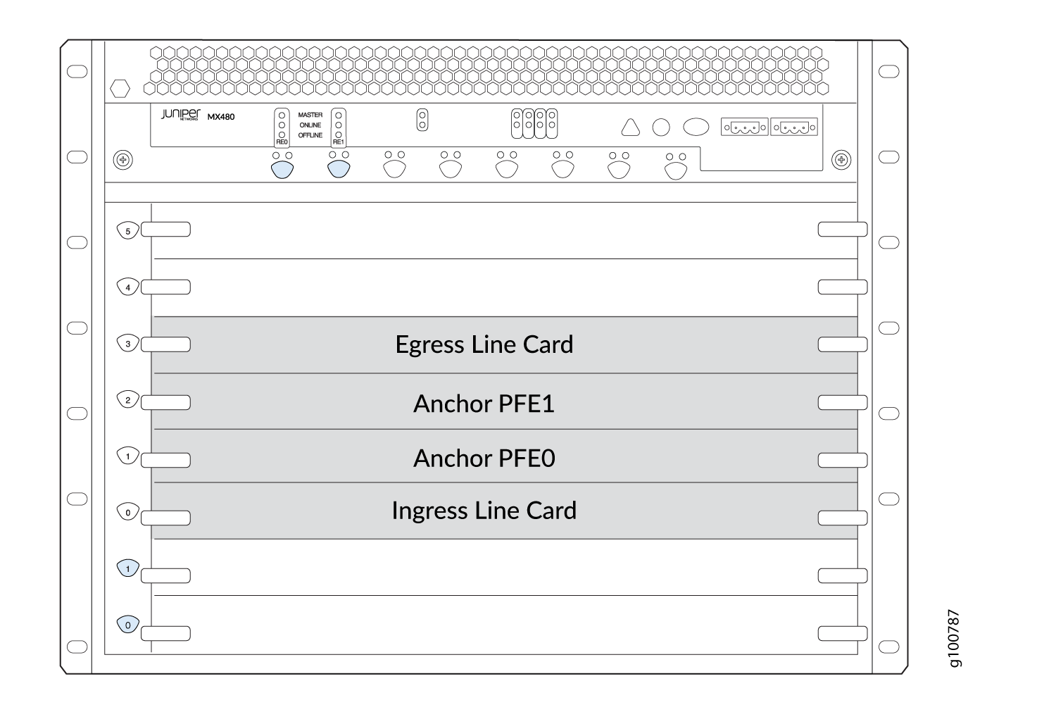
イングレスラインカード(スロット0)は、S1-Uインターフェイスを提供し、無線アクセスネットワーク(RAN)に接続し、Sxa/Sxbインターフェイスを組み合わせてSAEGW-Cに接続します。
アンカー PFE ライン カード(スロット 1 および 2)は、内部
pfe-インターフェイスを介したデータ トラフィックのコア処理を提供します。少なくとも1つのアンカーPFEカードが必要ですが、冗長性を提供するには2つが推奨されます。エグレスラインカード(スロット3)は、コアインターネットに接続するSGiインターフェイスを提供します。
MXシリーズルーターをJunosマルチアクセスユーザープレーンソリューションのSAEGW-Uとして設定する前に、以下を確認してください。
提供する少なくとも1つの設定SAEGW-C
eNodeB のリース時
パケット データ ネットワーク(PDN)へのアクセス
概要
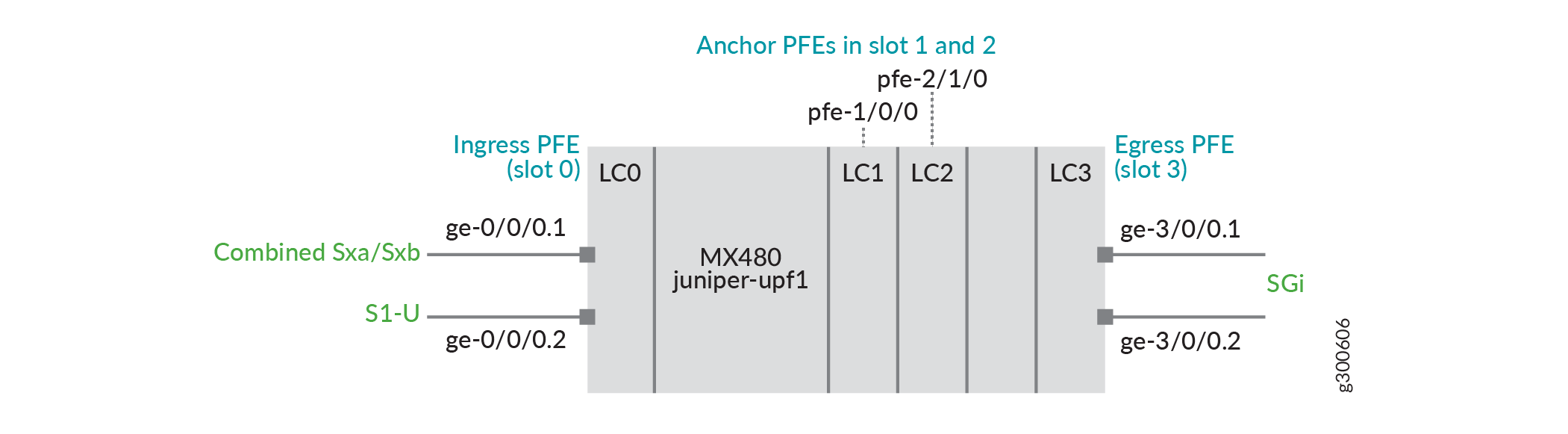
トポロジ
この例では( 図 2 を参照)。
MPC2はスロット0にge-0/0/0.1があり、Sxa/Sxbインターフェイスとge-0/0/0.2を組み合わせてS1-Uインターフェイスを提供します。
MPC7 は、アンカー PFE インターフェイスを提供するためにスロット 1 および 2 にあります。
MPC2はスロット3にge-3/0/0.1とge-3/0/0.2があり、SGiインターフェイスを提供しています。
 として設定する
構成
CLI クイックコンフィギュレーション
この例を迅速に設定するには、以下のコマンドをコピーしてテキスト ファイルに貼り付け、改行を削除し、ネットワーク設定に合わせて必要な詳細を変更し、コマンドを 階層レベルの CLI [edit] にコピー アンド ペーストします。
set system ddos-protection protocols pfcp aggregate bandwidth 20000
set system ddos-protection protocols pfcp aggregate burst 9000
set system ddos-protection protocols pfcp aggregate recover-time 30
set system ddos-protection protocols gtp-path-mgmt aggregate bandwidth 8400
set system ddos-protection protocols gtp-path-mgmt aggregate burst 8400
set system ddos-protection protocols gtp-path-mgmt aggregate recover-time 30
set chassis redundancy graceful-switchover
set chassis fpc 1 pfe 0 forwarding-packages mobility user-plane
set chassis fpc 2 pfe 1 forwarding-packages mobility user-plane
set chassis network-services enhanced-ip
set interfaces ge-0/0/0 vlan-tagging
set interfaces ge-0/0/0 unit 1 vlan-id 101
set interfaces ge-0/0/0 unit 2 vlan-id 102
set interfaces ge-0/0/0 unit 1 family inet address 10.0.0.1/24
set interfaces ge-0/0/0 unit 2 family inet address 20.0.0.1/24

set interfaces ge-3/0/0 vlan-tagging
set interfaces ge-3/0/0 unit 1 vlan-id 101
set interfaces ge-3/0/0 unit 2 vlan-id 102
set interfaces ge-3/0/0 unit 1 family inet address 30.0.1.1/24
set interfaces ge-3/0/0 unit 2 family inet address 30.0.2.1/24
set interfaces lo0 unit 0 family inet address 100.0.0.1/32
set interfaces mif unit 0 family inet
set interfaces mif unit 1 family inet
set interfaces apfe0 anchoring-options primary-list pfe-1/0/0
set interfaces apfe0 anchoring-options secondary pfe-2/1/0
set services mobile-edge gateways saegw juniper-upf1 control-plane-peers local-address 10.0.0.1
set services mobile-edge gateways saegw juniper-upf1 control-plane-peers path-management enable
set services mobile-edge gateways saegw juniper-upf1 control-plane-peers heartbeat-interval 60
set services mobile-edge gateways saegw juniper-upf1 control-plane-peers apn-services apns apn-default mobile-interface mif.0
set services mobile-edge gateways saegw juniper-upf1 control-plane-peers apn-services apns apn-vrf1 mobile-interface mif.1
set services mobile-edge gateways saegw juniper-upf1 access-network-peers local-address 20.0.0.1
set services mobile-edge gateways saegw juniper-upf1 system anchor-pfes interface apfe0
set routing-instances vrf1 instance-type virtual-router
set routing-instances vrf1 interface mif.1
set routing-instances vrf1 interface ge-3/0/0.2
set routing-instances vrf1 routing-options static route 0.0.0.0/0 next-table inet.0
手順
手順
次の例では、設定階層内のさまざまなレベルに移動する必要があります。CLIのナビゲーションについては、 設定モードでのCLIエディターの使用を参照してください。
MXルーターをSAEGW-Uとして設定するには::
-
PFCP プロトコル トラフィックの DDoS 攻撃防御を有効にします。
[edit system ddos-protection protocols]
user@host# set pfcp aggregate bandwidth 20000
user@host# set pfcp aggregate burst 9000
user@host# set pfcp aggregate recover-time 30
user@host# set gtp-path-mgmt aggregate bandwidth 8400
user@host# set gtp-path-mgmt aggregate burst 8400
user@host# set gtp-path-mgmt aggregate recover-time 30
-
グレースフル リスタート(GRES)を設定します。
[edit chassis]
user@host# set redundancy graceful-switchover
-
アンカー PFE 処理用にスロット 1 とスロット 2 を設定します。
[edit chassis]
user@host# set fpc 1 pfe 0 forwarding-packages mobility user-plane
user@host# set fpc 2 pfe 1 forwarding-packages mobility user-plane
-
拡張 IP ネットワーク サービスを実現します。
[edit chassis]
user@host# set network-services enhanced-ip
-
vlanを使用してイングレス論理インターフェイスを設定します。
[edit interfaces ge-0/0/0]
user@host# set vlan-tagging
user@host# set unit 1 vlan-id 101
user@host# set unit 2 vlan-id 102
user@host# set unit 1 family inet address 10.0.0.1/24
user@host# set unit 2 family inet address 20.0.0.1/24
-
VRF デフォルト(apn1)の加入者のコア/インターネットへのルーティングにエグレス PFE を設定します。
[edit interfaces ge-3/0/0]
user@host# set vlan-tagging
user@host# set unit 1 vlan-id 101
user@host# set unit 2 vlan-id 102
user@host# set unit 1 family inet address 30.0.1.1/24
user@host# set unit 2 family inet address 30.0.2.1/24
-
加入者 VRF のループバック アドレスとモバイル インターフェイスを設定します。
[edit interfaces lo0]
user@host# set unit 0 family inet address 100.0.0.1/32
[edit interfaces mif]
user@host# set unit 0 family inet
user@host# set unit 1 family inet
-
冗長性アンカー PFE インターフェイスを定義します。
[edit interfaces]
user@host# set apfe0 anchoring-options primary-list pfe-1/0/0
user@host# set apfe0 anchoring-options secondary pfe-2/1/0
-
SAEGW-Uゲートウェイ
juniper-upf1に名前を付け、PFCPピアがSAEGW-Uに接続するアドレスを設定します。また、SAEGW-U用に2つのAPNを設定します(apn-defaultデフォルトのルーティングインスタンスにセッションを配置し、apn-vrf1セッションを にVRF1設定します)。[edit services mobile-edge gateways] user@host# set saegw juniper-upf1 control-plane-peers local-address 10.0.0.1 [edit services mobile-edge gateways saegw juniper-upf1 control-plane-peers] user@host# set path-management enable user@host# set heartbeat-interval 60 user@host# set apn-services apns apn-default mobile-interface mif.0 user@host# set apn-services apns apn-vrf1 mobile-interface mif.1
-
GTP-UピアがSAEGW-Uに接続するアドレスを設定します。
メモ:これは、前のステップとは異なるコマンド階層で行われます。
[edit services mobile-edge gateways saegw juniper-upf1 access-network-peers]
user@host# set local-address 20.0.0.1
-
PFCP 処理のための集約インターフェイス
apfe0を設定します。[edit services mobile-edge gateways saegw juniper-upf1 system] user@host# set anchor-pfes interface apfe0
-
VRF vrf1(apn2)の加入者のコア/インターネットへのルーティングにエグレス PFE を設定します。
[edit routing-instances vrf1]
user@host# set instance-type virtual-router
user@host# set interface mif.1
user@host# set interface ge-3/0/0.2
user@host# set routing-options static route 0.0.0.0/0 next-table inet.0
結果
設定モードから、 、show routing-instancesshow interfacesshow servicesおよび のコマンドをshow chassis入力して、設定をshow unified-edge確認します。出力結果に意図した設定が表示されない場合は、この例の手順を繰り返して設定を修正します。
user@host# show system
ddos-protection {
    protocols {
        gtp-path-mgmt {
            aggregate {
                bandwidth 8400;
                burst 8400;
                recover-time 30;
            }
        }
        pfcp {
            aggregate {
                bandwidth 20000;
                burst 9000;
                recover-time 30;
            }
        }
    }
}
user@host# show chassis
redundancy {
    graceful-switchover;
}
fpc 1 {
    pfe 0 {
        forwarding-packages {
            mobility {
                user-plane;
            }
        }
    }
}
fpc 2 {
    pfe 1 {
        forwarding-packages {
            mobility {
                user-plane;
            }
        }
    }
}
network-services {
    enhanced-ip;
}
user@host# show interfaces
ge-0/0/0 {
    vlan-tagging {
        unit 1 {
            vlan-id 101;
        }
        unit 2 {
            vlan-id 102;
        }
    }
    unit 1 {
        family inet {
            address 10.0.0.1/24;
        }
    }
    unit 2 {
        family inet {            address 20.0.0.1/24;
        }
    }
}
ge-3/0/0 {
    vlan-tagging {
        unit 1 {
            vlan-id 101;
        }
        unit 2 {
            vlan-id 102;
        }
    }
    unit 1 {
        family inet {
            address 30.0.1.1/24;
        }
    }
    unit 2 {
        family inet {
            address 30.0.2.1/24;
        }
    }
}
apfe0 {
    anchoring-options {
        primary-list {
            pfe-1/0/0;
        }
        secondary pfe-2/1/0;
    }
}
lo0 {
    unit 0 {
        family inet {
            address 100.0.0.1/32;
        }
    }
}
mif {
    unit 0 {
        family inet;
    }
    unit 1 {
        family inet;
    }
}
user@host# show services
mobile-edge {
    gateways {
        saegw juniper-upf1 {
            system {
                anchor-pfes {
                    interface apfe0;
                }
            }
            control-plane-peers {
                local-address 10.0.0.1;
                path-management enable;
                heartbeat-interval 60;
                apn-services {
                    apns apn-default {
                        mobile-interface mif.0;
                    }
                    apns apn-vrf1 {
                        mobile-interface mif.1;
                    }
                }
            }
            access-network-peers {
                local-address 20.0.0.1;
            }
        }
    }
}
デバイスの設定が完了したら、設定モードから を入力します commit 。
検証
さまざまな show コマンドを使用して、SAEGW-Uが正常に機能していることを確認します。
SAEGW-U状態の確認
目的
SAEGW-Uが実行されており、GRESが有効になっていることを確認します。
アクション
user@host> show services mobile-edge summary
Graceful-Restart        Enabled
Mastership              Master
State                   Running
Bulk Sync               Synchronized
SAEGW-Uピアの検証
目的
SAEGW-Uが接続されており、SAEGW-Cs(コントロールピア)およびeNodeB(アクセスピア)と通信していることを確認します。
アクション
user@host> show services mobile-edge peers statistics
Peers Summary:
    Total control peers: 1
    Total access peers:  1
    Total association setup request rejects:  0

Control Peer Statistics:
    IP address:         10.0.0.0
    Hostname:           saegw-c1
    Routing-Instance:   default

    Heartbeat Requests Received:             11
    Heartbeat Responses Sent:                11

    Heartbeat Requests Sent:                 2
    Heartbeat Responses Received:            2

    Association Setup Requests Received:     1
    Association Setup Responses Sent:        1

    Association Release Requests Received:   0
    Association Release Responses Sent:      0

    Session Establishment Requests Received: 30000
    Session Establishment Responses Sent (Accepted):    30000
    Session Establishment Responses Sent (Rejected):    0

    Session Modification Requests Received:             30000
    Session Modification Responses Sent (Accepted):     30000
    Session Modification Responses Sent (Rejected):     0

    Session Deletion Requests Received:                 23169
    Session Deletion Responses Sent (Accepted):         22968
    Session Deletion Responses Sent (Rejected):         0

Access Peer Statistics:
    IP address:         20.0.0.0
    Routing-Instance:   default

    Echo Requests Received:                 0
    Echo Responses Sent:                    0
    Echo Requests Sent:                     0
    Echo Responses Received:                0
SAEGW-Uセッションの検証
目的
SAEGW-Uにアクティブなデータセッションがあることを確認します。
アクション
user@host> show services mobile-edge sessions summary
Sessions by State:
    SESSION_WAIT: 35
    ESTABLISHED: 18561
    Total: 18596

Bearers by State:
    BEARER_WAIT: 30
    ESTABLISHED: 18561
    Total: 18591
user@host> show services mobile-edge sessions
    Session-address: 23.0.21.163 State: ESTABLISHED Num-bearers: 1
        VRF-ID: 0x0 APN: default
        CPF-peer: 10.0.0.2 Access-peer: 20.0.0.2
        Anchor-PFE: apfe0:pfe-1/0/0 Secondary-anchor-PFE: apfe0:pfe-2/1/0
        Local-SEID: 0x20015a2 Remote-SEID: 0x3cb2

    Session-address: 23.0.47.237 State: ESTABLISHED Num-bearers: 1
        VRF-ID: 0x0 APN: default
        CPF-peer: 10.0.0.2 Access-peer: 20.0.0.2
        Anchor-PFE: apfe0:pfe-1/0/0 Secondary-anchor-PFE: apfe0:pfe-2/1/0
        Local-SEID: 0x2fec Remote-SEID: 0x56fc

    Session-address: 23.0.21.49 State: ESTABLISHED Num-bearers: 1
        VRF-ID: 0x0 APN: default
        CPF-peer: 10.0.0.2 Access-peer: 20.0.0.2
        Anchor-PFE: apfe0:pfe-1/0/0 Secondary-anchor-PFE: apfe0:pfe-2/1/0
        Local-SEID: 0x1531 Remote-SEID: 0x3c40

    Session-address: 23.0.29.83 State: ESTABLISHED Num-bearers: 1
        VRF-ID: 0x0 APN: default
        CPF-peer: 10.0.0.2 Access-peer: 20.0.0.2
        Anchor-PFE: apfe0:pfe-1/0/0 Secondary-anchor-PFE: apfe0:pfe-2/1/0
        Local-SEID: 0x2001d53 Remote-SEID: 0x4462

....