LDP の概要
LDPの概要
LDP(Label Distribution Protocol)は、トラフィックエンジニアリングを行っていないアプリケーションでラベルを配布するためのプロトコルです。LDP を使用すると、ルーターはネットワーク層の経路情報をデータリンク層の経路に直接マッピングすることで、ネットワークを介したラベル交換パス(LSP)を確立できます。
これらのLSPは、直接接続されたネイバー(IPホップバイホップ転送に相当)をエンドポイントとする場合もあれば、ネットワークの出口ノードで、すべての中間ノードを介した切り替えを可能にする場合もあります。LDP で確立した LSP は、RSVP で作成したトラフィックエンジニアリング LSP も通過できます。
LDP は、作成する各 LSP に FEC(Forwarding Equivalence Class)を関連付けます。LSP に関連する FEC は、どのパケットがその LSP にマッピングされるかを指定します。各ルーターは、ネクスト ホップが FEC 用にアドバタイズするラベルを選択し、他のすべてのルーターにアドバタイズするラベルにスプライスすることで、LSP はネットワークを介して拡張されます。このプロセスは、egressルーターに収束するLSPのツリーを形成します。
LDPシグナリングプロトコルを理解する
LDPは、MPLSサポート用に設定されたデバイスで実行されるシグナリングプロトコルです。MPLSとLDPの両方が正常に設定されると、LDPインターフェイス全体でTCPパケットの交換を開始します。パケットは、ネットワーク内でMPLS情報の交換のためのTCPベースのLDPセッションを確立します。LSPを確立するには、適切なインターフェイスでMPLSとLDPの両方を有効化すれば十分です。
LDPは、MPLSネットワーク内でLSP隣接関係を自動的に確立する、シンプルで即効性のあるシグナリングプロトコルです。次に、ルーターは、隣接関係間でhelloパケットやLSPアドバタイズメントなどのLSPアップデートを共有します。LDPはIS-ISやOSPFなどのIGP上で実行されるため、LDPとIGPを同じインターフェイスセットで設定する必要があります。両方を設定した後、LDPはすべてのLDP対応インターフェイスを介してLDPメッセージの送受信を開始します。LDPは単純であるため、RSVPが実行できる真のトラフィック制御を実行することはできません。LDPは、帯域幅予約やトラフィックの制約をサポートしていません。
LSR( ラベルスイッチングルーター )でLDPを設定すると、ルーターはすべてのLDP対応インターフェイスからLDPディスカバリーメッセージの送信を開始します。隣接する LSR が LDP ディスカバリーメッセージを受信すると、基盤となる TCP セッションを確立します。次に、TCPセッションの最上位にLDPセッションが作成されます。TCPスリーウェイハンドシェイクは、LDPセッションが双方向接続であることを保証します。LDPセッションを確立した後、LDPネイバーはメッセージを交換してセッションを維持および終了します。LDPアドバタイズメッセージにより、LSRはラベル情報を交換して、特定のLSP内のネクストホップを決定できます。ルーターの障害などのトポロジーの変更により、LDPセッションを終了したり、LSPの変更を伝送するための追加のLDPアドバタイズを生成したりできるLDP通知が生成されます。
Junos OSリリース20.3R1以降、コントロールプレーン機能を備えたLDPシグナリングプロトコル設定を提供するMPLSのサポート。
例:LDP シグナル化 LSP の設定
この例では、MPLS ネットワーク内で LDP インスタンスを作成および設定する方法を示します。
要件
始める前に:
ネットワークインターフェイスを設定します。 セキュリティデバイス向けインターフェイスユーザーガイドを参照してください。
ネットワーク全体で IGP を設定します。(LDP の設定は既存の IGP 設定に追加され、MPLS 設定に含まれます)。
MPLSネットワーク内のすべてのトランジットインターフェイスでMPLSを有効にして、LSP確立にLDPを使用するようにネットワークを設定します。
注:LDPはIS-ISやOSPFなどのIGP上で実行されるため、LDPとIGPを同じインターフェイスセットで設定する必要があります。
概要
LDPシグナリングLSPを設定するには、MPLSネットワークのすべてのトランジットインターフェイスでMPLSファミリーを有効にし、[protocols mpls]および[protocols ldp]階層レベルのすべてのトランジットインターフェイスを含める必要があります。
この例では、MPLSファミリーを有効化し、すべてのトランジットインターフェイスでLDPインスタンスを作成します。さらに、MPLSネットワークのすべてのトランジットインターフェイスでMPLSプロセスを有効にします。この例では、 図 1 に示すようにサンプル ネットワークを設定します。
設定
手順
CLIクイックコンフィグレーション
この例を迅速に設定するには、以下のコマンドをコピーしてテキストファイルに貼り付け、改行を削除し、ネットワーク設定に一致させる必要がある詳細情報を変更し、コマンドを [edit] 階層レベルでCLIにコピーアンドペーストして、設定モードから commit を入力します。
R1
set interfaces ge-0/0/0 unit 0 family mpls
set protocols mpls ge-0/0/0 unit 0
set protocols ldp interface ge-0/0/0 unit 0
R2
set interfaces ge-0/0/0 unit 0 family mpls
set protocols mpls ge-0/0/0 unit 0
set protocols ldp interface ge-0/0/0 unit 0
set interfaces ge-0/0/1 unit 0 family mpls
set protocols mpls ge-0/0/1 unit 0
set protocols ldp interface ge-0/0/1 unit 0
R3
set interfaces ge-0/0/0 unit 0 family mpls
set protocols mpls ge-0/0/0 unit 0
set protocols ldp interface ge-0/0/0 unit 0
ステップバイステップの手順
MPLSネットワーク内でLDPインスタンスを有効にするには:
ルーター R1 のトランジット インターフェイスで MPLS ファミリーを有効にします。
[edit]
user@R1# set interfaces ge-0/0/0 unit 0 family mpls
トランジット インターフェイスで MPLS プロセスを有効にします。
[edit]
user@R1# set protocols mpls interface ge-0/0/0 unit 0
トランジットインターフェイスでLDPインスタンスを作成します。
[edit]
user@R1# set protocols ldp interface ge-0/0/0 unit 0
結果
設定モードから show コマンドを入力して、設定を確認します。出力に意図した設定が表示されない場合は、この例の設定手順を繰り返して修正します。
簡潔にするために、この show 出力には、この例に関連する設定のみ含まれています。システム上のその他の設定はすべて省略記号(...)で置き換えられています。
user@R1# show
...
    interfaces {
        ge-0/0/0 {
            unit 0 {
                family inet {
                    address 10.100.37.20/24;
                }
                family mpls;
            }
        }
        }
    ...
        protocols {
            mpls {
                interface all;
            }
            ldp {
                interface ge-0/0/0.0;
            }
        }
デバイスの設定が完了したら、設定モードから commit コマンドを入力して設定を有効化します。
Junos OS LDP プロトコルの実装
LDPのJunos OS実装は、LDPバージョン1をサポートしています。Junos OSは、内部ゲートウェイプロトコル(IGP)のルーター間でトンネリングするためのシンプルなメカニズムをサポートしており、コア内での外部ルートの必要な配信を排除しています。Junos OSでは、ネットワーク内のすべてのエグレスルーターへのMPLSトンネルネクストホップを許可し、コアで実行されているIGPのみでエグレスルーターにルートを分配できます。エッジルーターはBGPを実行しますが、外部ルートをコアに配信しません。代わりに、エッジでの再帰的なルート検索では、egressルーターに切り替えられたLSPに解決されます。トランジット LDP ルーターには外部ルートは必要ありません。
LDP動作
LDP を実行したいインターフェイスごとに LDP を設定する必要があります。LDPは、後続のBGPネクストホップであるルーターIDアドレス用に各egressルーターをルートとするLSPツリーを作成します。イングレス ポイントは、LDP を実行しているすべてのルーターにあります。このプロセスは、すべてのegressルーターにinet.3ルートを提供します。BGPが実行されている場合、最初にinet.3テーブルを使用してネクストホップを解決しようとし、これにより、すべてではないにしても、ほとんどのBGPルートがMPLSトンネルのネクストホップにバインドされます。
LDP を実行している 2 つの隣接ルーターはネイバーになります。2 つのルーターが複数のインターフェイスで接続されている場合、各インターフェイスでネイバーになります。LDP ルーターがネイバーになると、ラベル情報を交換するための LDP セッションを確立します。両方のルーターでルーターごとのラベルが使用されている場合、複数のインターフェイス上のネイバーであっても、その間で 1 つの LDP セッションのみが確立されます。このため、LDP セッションは特定のインターフェイスとは関係ありません。
LDPは、ユニキャストルーティングプロトコルと組み合わせて動作します。LDP は、LDP とルーティングプロトコルが有効になっている場合にのみ LSP をインストールします。このため、LDPとルーティングプロトコルの両方を同じインターフェイスセットで有効にする必要があります。これが行われないと、各egressルーターとすべてのingressルーターの間にLSPが確立されず、BGPルーティングされたトラフィックが失われる可能性があります。
LDP を介して他のルーターから受信したり、他のルーターに配信したりするラベルにポリシー フィルターを適用できます。ポリシーフィルターは、LSPの確立を制御するメカニズムを提供します。
インターフェイス上で LDP を実行するためには、そのインターフェイス上の 論理インターフェイス で MPLS が有効になっている必要があります。詳細については、 論理インターフェイスを参照してください。
LDPメッセージタイプ
LDPは、次のセクションで説明するメッセージタイプを使用して、マッピングの確立と削除、およびエラーの報告を行います。すべてのLDPメッセージは、タイプ、長さ、および値(TLV)エンコーディングスキームを使用する共通の構造を持っています。
ディスカバリーメッセージ
ディスカバリーメッセージは、ネットワーク内のルーターの存在を通知および維持します。ルーターは、helloメッセージを定期的に送信することにより、ネットワーク内にルーターが存在することを示します。helloメッセージは、サブネット上のすべてのルーターのグループマルチキャストアドレスにあるLDPポートにUDPパケットとして送信されます。
LDPは、以下のディスカバリー手順を使用します。
基本的なディスカバリー—ルーターは、インターフェイスを介してLDPリンクhelloメッセージを定期的に送信します。LDPリンクhelloメッセージは、LDPディスカバリーポートにアドレス指定されたUDPパケットとして送信されます。インターフェイスでLDPリンクhelloメッセージを受信すると、LDPピアルーターとの隣接関係が識別されます。
拡張ディスカバリー—直接接続されていないルーター間のLDPセッションは、LDP拡張ディスカバリーによってサポートされています。ルーターは、LDPターゲットhelloメッセージを特定のアドレスに定期的に送信します。ターゲットhelloメッセージは、特定のアドレスのLDPディスカバリーポートにアドレス指定されたUDPパケットとして送信されます。ターゲットルーターは、ターゲットhelloメッセージに応答するか無視するかを決定します。応答を選択したターゲットルーターは、ターゲットhelloメッセージを開始ルーターに定期的に送信することによって応答します。
セッションメッセージ
セッションメッセージは、LDPピア間のセッションを確立、維持、および終了します。ルーターは、helloメッセージを通じて学習した別のルーターとのセッションを確立するときに、TCPトランスポートを介してLDP初期化手順を使用します。初期化手順が正常に完了すると、2つのルーターはLDPピアになり、アドバタイズメッセージを交換できます。
アドバタイズメッセージ
アドバタイズメッセージは、転送等価クラス(FEC)のラベルマッピングを作成、変更、および削除します。ラベルの要求またはピアへのラベルマッピングのアドバタイズは、ローカルルーターによって決定されます。一般に、ルーターは、ラベルが必要なときに隣接するルーターにラベルマッピングを要求し、隣接するラベルにラベルを使用させたいときは隣接ルーターにラベルマッピングをアドバタイズします。
通知メッセージ
通知メッセージは、アドバイザリ情報と信号エラー情報を提供します。LDPは、通知メッセージを送信して、エラーやその他のイベントを報告します。LDP通知メッセージには2種類あります。
致命的なエラーを通知するエラー通知。ルーターがLDPセッションのピアからエラー通知を受信した場合、セッションのTCPトランスポート接続を閉じ、セッションを通じて学習したすべてのラベルマッピングを破棄することで、LDPセッションを終了します。
アドバイザリ通知は、LDP セッションに関する情報、またはピアから受信した以前のメッセージのステータスをルーターに渡します。
RSVP LSP における LDP LSP のトンネリング
LDP LSP を RSVP LSP 上でトンネル化できます。以下のセクションでは、RSVP LSP における LDP LSP のトンネリングの仕組みについて説明します。
RSVP LSP における LDP LSP トンネリングの概要
トラフィック制御にRSVPを使用している場合は、LDPを同時に実行して、コア内の外部ルートの分配を排除することができます。LDP によって確立された LSP は、RSVP によって確立された LSP を介してトンネリングされます。LDP は、トラフィック制御された LSP をシングル ホップとして効果的に処理します。
RSVP が確立した LSP 間で LDP を実行するようにルーターを設定すると、LDP は LSP のもう一方の端でルーターとのセッションを自動的に確立します。LDP 制御パケットは、LSP を介する伝送ではなく、ルーティングされたホップバイホップです。このルーティングでは、シンプレックス(一方向)トラフィックエンジニアリングLSPを使用することができます。逆方向のトラフィックは、トラフィックエンジニアリングされたトンネルではなく、ユニキャストルーティングに追従するLDPで確立されたLSPを経由してフローします。
RSVP LSP を介して LDP を設定する場合、トラフィック制御されたコアと周辺の LDP クラウドで複数の OSPF エリアと IS-IS レベルを設定することができます。
Junos OSリリース15.1以降、マルチインスタンスのサポートは、仮想ルータールーティングインスタンスのRSVPトンネリングを介してLDPに拡張されます。これにより、単一のルーティングおよび MPLS ドメインを複数のドメインに分割でき、各ドメインを個別にスケーリングできます。BGPラベル付きユニキャストを使用して、これらのドメインをサービス転送等価クラス(FEC)のためにステッチすることができます。各ドメインは、MPLS転送にドメイン内LDP-over-RSVP LSPを使用します。
LDP-over-RSVP LSP のマルチインスタンス サポートを導入すると、すでに別のルーティング インスタンスに割り当てられているインターフェイスで MPLS を有効にすることはできません。 [edit protocols mpls] 階層レベルで別のルーティング インスタンスの一部であるインターフェイスを追加すると、コミット時に設定エラーが発生します。
RSVP LSP で LDP LSP をトンネリングするメリット
LDP LSP を RSVP LSP でトンネリングすると、以下のメリットが得られます。
レイヤー 2 およびレイヤー 3 VPN で、IPv4、IPv6、ユニキャスト、マルチキャストなどの異なるトラフィック タイプのコンバージェンスを提供します。
複数のトポロジー、異なるプロトコル、および複数の管理境界に対応できる柔軟なアクセス接続オプションを有効にします。
複数のプロバイダー間のセキュアなインターワーキングを可能にします。
RSVP-TEは、トラフィックエンジニアリング、帯域幅保証、リンクおよびノードの冗長性機能をサポートしているため、顧客ごとに差別化されたサービスの提供を可能にします。
コアで必要 LSP 数を削減することで、プロトコルやルーターのリソース要件を削減するとともに、コンバージェンス時間を短縮します。
直接接続されたネイバーへのポイントツーポイントの TE トンネルを使用して LSP を構築するため、ネットワークの中断を最小限に抑えた、費用対効果の高いロールアウトを提供します。これらの TE トンネルは、エンドツーエンドではなく、ネクスト ホップまでしか行きません。次に、LDP がそれらのトンネル上で実行されると、直接接続されたネイバーにセッションが構築されます。新しいノードの追加など、ネットワークに変更が発生した場合、新しいノードの直接接続されたネイバーは、RSVP や LDP セッションを行います。したがって、RSVP LSP はネクスト ホップへのものだけであり、LDP は新しいアドレスのラベルのアドバタイズを行います。
SR-TE上のLDPのトンネリング
メリットについて学習し、SR-TE 上の LDP トンネリングの概要を理解します。
LDP を SR-TE 上でトンネリングするメリット
コア ネットワークの SR-TE 上で LDP のシームレスな統合を可能にします。
複数のトポロジー、プロトコル、ドメインに対応する柔軟な接続オプションを提供します。
LDP と SR 対応デバイス間の相互運用性を可能にします。
SR-TE負荷分散機能を活用します。
SR-TEドメイン内のTI-LFA(トポロジー独立ループフリー代替)を使用して、ネットワーク接続をより早く回復します。TI-LFA を使用する SR は、プライマリ パスに障害が発生したり利用できなくなったりした場合、バックアップ パスや代替パスに瞬時にトラフィックをルーティングします。
SR-TE上のLDPのトンネリングの概要
サービス プロバイダは通常、ネットワークのエッジで MPLS トランスポートとともに LDP シグナリング プロトコルを使用します。LDP はシンプルであるという利点がありますが、ネットワークのコアで必要とされることの多い TE(トラフィック制御)や洗練されたパス修復機能がありません。多くのサービスプロバイダは、コアにおいてRSVPからセグメントルーティングトラフィックエンジニアリング(SR-TE)への移行を進めています。SR-TEは、SPRING(source routing in packet networks)とも呼ばれます。
エッジでLDPを実行しているルーターは、SR機能をサポートしていない可能性があります。サービスプロバイダは、アップグレードの必要性を避けるために、これらのルーターで引き続きLDPを使用することを望むかもしれません。このようなシナリオでは、SR-TE 上の LDP トンネリング機能により、SR 機能を持たないルーター(LDP を実行している)と SR 機能を持つルーター(SR-TE を実行している)を統合する機能が提供されます。
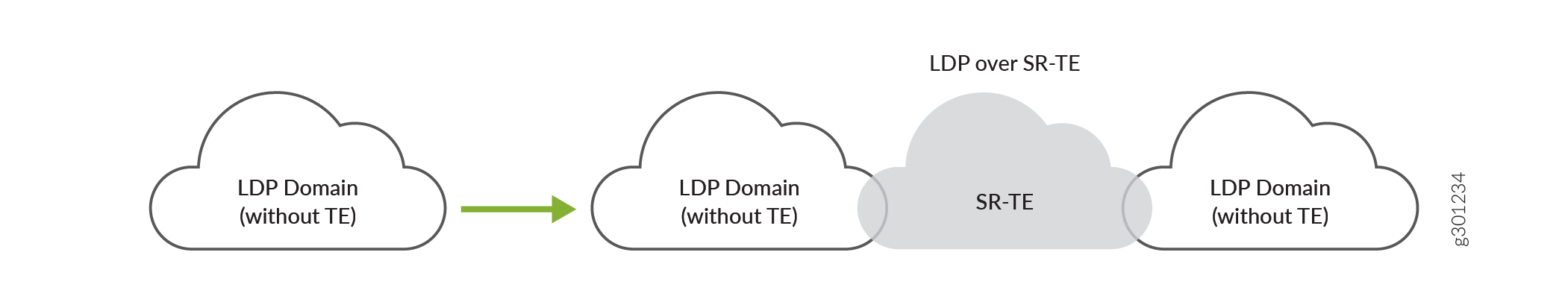
LDP LSP は SR-TE ネットワークを介してトンネリングされるため、LDP LSP と SR-TE LSP とのインターワーキングが可能になります。例えば、プロバイダのエッジネットワークにLDPドメインがあり、コアネットワークにSR-TEがある場合、 図2に示すように、LDPドメインをSR-TE経由で接続できます。
SR-TE 上での LDP のトンネリングは、LDP LSP と SR-TE LSP の両方の共存をサポートします。
 のSR-TEを介してLDPドメインを相互接続する
リージョン間のコアネットワークに接続されたLDPドメイン間で、SR-TE上でLDPをトンネルすることもできます。例えば、複数のリージョン LDP ドメインがリージョン間の SR-TE コア ネットワークに接続されている場合、 図 3 に示すように、リージョン間の SR-TE コア ネットワーク全体で LDP をトンネルできます。
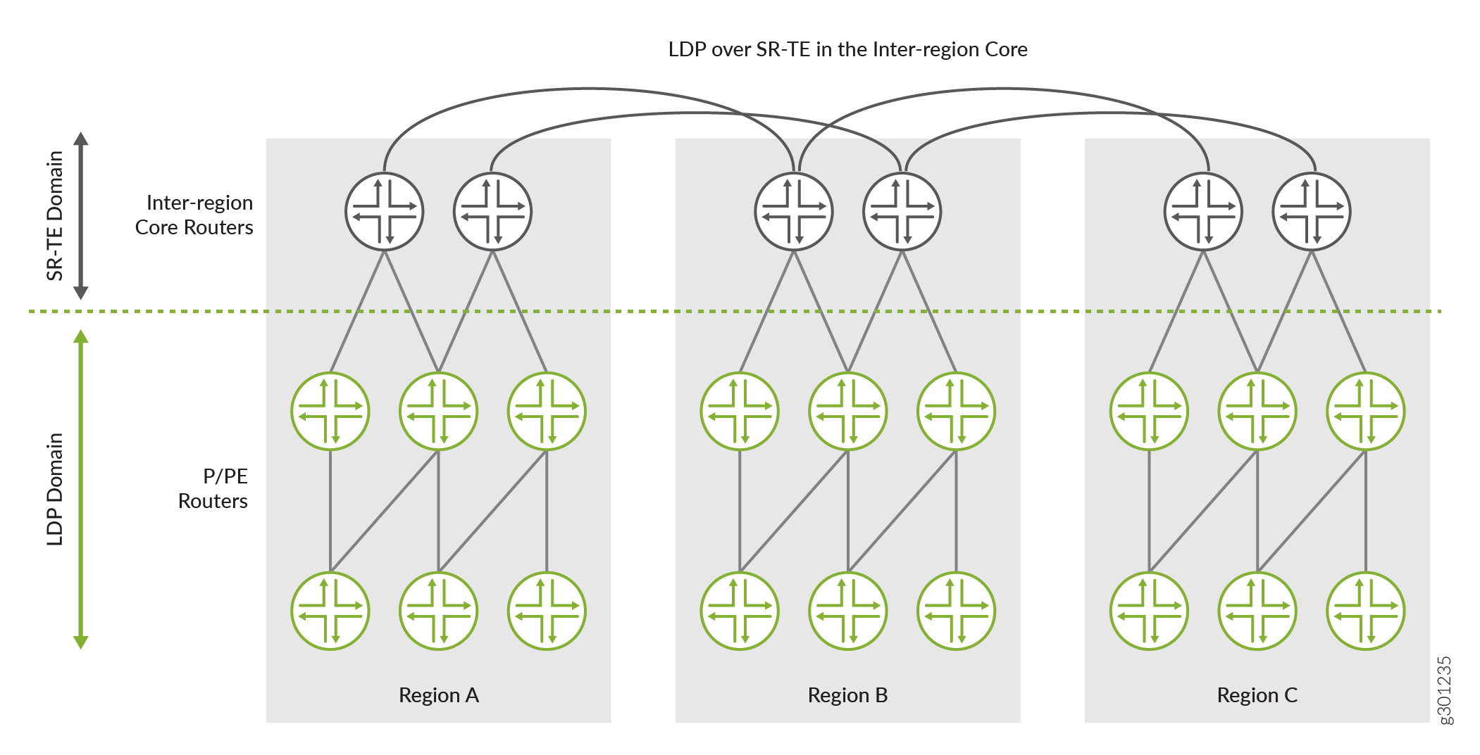
図3では、3つのリージョンネットワーク(A、B、C)がLDPを実行しています。これらのリージョン LDP ドメインは、SR-TE を実行しているそれぞれのリージョン コア ネットワークに接続されています。リージョン SR-TE コア ネットワークは、さらに他のリージョン SR-TE コア ネットワーク(リージョン間コア ネットワーク)に相互接続されています。これらのリージョン間の SR-TE コア ネットワーク上に LDP をトンネルし、レイヤー 3 VPN などのサービスをシームレスに導入できます。このシナリオは、コアアグリゲーション層がSR-TE上でトンネリングされたLDPを実行し、アクセス層がLDPのみを実行するモバイルバックホールネットワークで使用できます。
IS-ISネットワークでSR-TEを介したLDPトンネリングを有効にするには、以下の設定ステートメントを設定する必要があります。
-
ldp-tunneling[edit protocols source-packet-routing source-routing-path source-routing-path-name] 階層レベルで、SR-TE 上の LDP トンネリングを有効にします。 -
spring-te[edit protocols isis traffic-engineering tunnel-source-protocol] 階層レベルで、SR-TE LSP 上の LDP をトンネル送信元プロトコルとして選択します。
OSPFネットワークでSR-TEを介したLDPトンネリングを有効にするには、以下の設定ステートメントを設定する必要があります:
-
ldp-tunneling[edit protocols source-packet-routing source-routing-path source-routing-path-name] 階層レベルで、SR-TE 上の LDP トンネリングを有効にします。 -
spring-te[edit protocols ospf traffic-engineering tunnel-source-protocol] 階層レベルで、SR-TE LSP 上の LDP をトンネル送信元プロトコルとして選択します。
IGP(IS-ISおよびOSPF)用に複数のトンネルソースプロトコルを設定して、ショートカットルートを作成できます。複数のトンネル ソース プロトコルが設定されていて、ある宛先に複数のプロトコルのトンネルが利用可能な場合、最も優先されるルートを持つトンネルが確立されます。例えば、コアネットワークにRSVP LSPとSR-TE LSPの両方があり、RSVPとSR-TE LSPの両方でLDPトンネリングが有効になっている場合、 tunnel-source-protocol 設定は優先値に基づいてトンネルを選択します。優先値が最も低いトンネルが最も優先されます。次の例のように、優先値を設定することで、すべての宛先に対して特定のプロトコルでこのルート優先値を上書きできます。
[edit]
user@host#set protocols isis traffic-engineering tunnel-source-protocol spring-te preference 2
user@host#set protocols isis traffic-engineering tunnel-source-protocol rsvp preference 5
[edit]
user@host#set protocols ospf traffic-engineering tunnel-source-protocol spring-te preference 2
user@host#set protocols ospf traffic-engineering tunnel-source-protocol rsvp preference 5
この例では、SR-TE トンネル ソース プロトコルに設定された優先値が 2 で、RSVP トンネル ソース プロトコルの優先値が 5 であることがわかります。この場合、SR-TEトンネルは、RSVPトンネルソースプロトコルと比較して、優先値が最も低いため、優先されます。
トンネル ソース プロトコル優先値の設定は必須ではありません。複数のトンネル ソース プロトコルが同じ優先値を持つ場合、宛先への優先ルートに基づいてトンネルが確立されます。
ターゲットLDPセッションが確立され、SR-TE LSPが立ち上がるとトリガーされます。LSP セッションは、LDP トンネリング(ldp-tunneling)の設定が削除されるか、SR-TE LSP が設定から削除されるまで、確立されたままとなります。
Junos OSは現在、色付きSR-TE LSP上のLDPをサポートしていません。
例:IS-ISネットワークにおけるSR-TEを介したLDPのトンネリング
この例では、コアネットワークのSR-TE上でLDP LSPをトンネル化する方法を学習します。
この例は、当社のコンテンツテストチームが検証し、更新しました。
要件
この例では、以下のハードウェアおよびソフトウェアコンポーネントを使用しています。
MXシリーズルーターをCE、PE、コアルーターとして使用します。
-
すべてのデバイスで実行されている Junos OS リリース 20.3R1 以降。
-
Junos OSリリース21.1R1でvMXを使用して更新および再検証しました。
-
この機能のハンズオンに興味はありませんか?
ジュニパー vLabs にアクセスして、設定済みの vLab サンドボックスを予約してください。 セグメントルーティング - ベーシックを無料で お試しいただけます。
概要
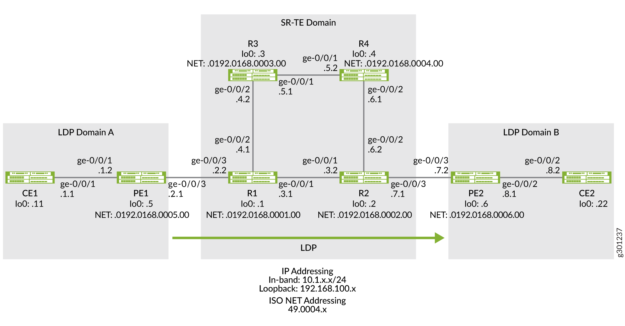
次のトポロジー(図4)は、SR-TEコアネットワークに接続された2つのLDPドメイン(LDPドメインAとLDPドメインB)を示しており、LSPセッションをSR-TE上でトンネリングすることでコア上に拡張しています。
トポロジー
 におけるSR-TE上のLDPのトンネリング
設定
コアネットワークでSR-TE上でLDP LSPをトンネルするには、以下のタスクを実行します。
CLIクイックコンフィグレーション
この例をすばやく設定するには、以下のコマンドをコピーしてテキストファイルに貼り付け、改行を削除し、ネットワーク設定に一致させる必要がある詳細情報を変更し、コマンドを [edit] 階層レベルでCLIにコピーアンドペーストして、設定モードから commit を入力します。
デバイスCE1
set chassis network-services enhanced-ip
set interfaces ge-0/0/1 description CE1-to-PE1
set interfaces ge-0/0/1 unit 0 family inet address 10.1.1.1/24
set interfaces lo0 unit 0 family inet address 192.168.100.11/32
set protocols ospf area 0.0.0.0 interface ge-0/0/1.0
set protocols ospf area 0.0.0.0 interface lo0.0 passive
set routing-options router-id 192.168.100.11
デバイスPE1
set chassis network-services enhanced-ip
set interfaces ge-0/0/1 description PE1-to-CE1
set interfaces ge-0/0/1 unit 0 family inet address 10.1.1.2/24
set interfaces ge-0/0/1 unit 0 family iso
set interfaces ge-0/0/3 description PE1-to-R1
set interfaces ge-0/0/3 unit 0 family inet address 10.1.2.1/24
set interfaces ge-0/0/3 unit 0 family iso
set interfaces ge-0/0/3 unit 0 family mpls
set interfaces lo0 unit 0 family inet address 192.168.100.5/32
set interfaces lo0 unit 0 family iso address 49.0004.0192.0168.0005.00
set interfaces lo0 unit 0 family mpls
set policy-options policy-statement export_bgp term a from protocol bgp
set policy-options policy-statement export_bgp term a from protocol direct
set policy-options policy-statement export_bgp term a then accept
set routing-instances CE1_vpn1 instance-type vrf
set routing-instances CE1_vpn1 protocols ospf area 0.0.0.0 interface ge-0/0/1.0
set routing-instances CE1_vpn1 protocols ospf export export_bgp
set routing-instances CE1_vpn1 interface ge-0/0/1.0
set routing-instances CE1_vpn1 route-distinguisher 192.168.100.5:1
set routing-instances CE1_vpn1 vrf-target target:100:4
set routing-instances CE1_vpn1 vrf-table-label
set protocols bgp group ibgp1 type internal
set protocols bgp group ibgp1 local-address 192.168.100.5
set protocols bgp group ibgp1 family inet unicast
set protocols bgp group ibgp1 family inet-vpn unicast
set protocols bgp group ibgp1 neighbor 192.168.100.6
set protocols isis interface ge-0/0/3.0 point-to-point
set protocols isis interface lo0.0 passive
set protocols ldp interface ge-0/0/3.0
set protocols ldp interface lo0.0
set protocols mpls interface ge-0/0/3.0
set protocols mpls interface lo0.0
set routing-options router-id 192.168.100.5
set routing-options autonomous-system 65410
デバイスR1
set chassis network-services enhanced-ip
set interfaces ge-0/0/1 description R1-to-R2
set interfaces ge-0/0/1 unit 0 family inet address 10.1.3.1/24
set interfaces ge-0/0/1 unit 0 family iso
set interfaces ge-0/0/1 unit 0 family mpls maximum-labels 8
set interfaces ge-0/0/2 description R1-to-R3
set interfaces ge-0/0/2 unit 0 family inet address 10.1.4.1/24
set interfaces ge-0/0/2 unit 0 family iso
set interfaces ge-0/0/2 unit 0 family mpls maximum-labels 8
set interfaces ge-0/0/3 description R1-to-PE1
set interfaces ge-0/0/3 unit 0 family inet address 10.1.2.2/24
set interfaces ge-0/0/3 unit 0 family iso
set interfaces ge-0/0/3 unit 0 family mpls maximum-labels 8
set interfaces lo0 unit 0 family inet address 192.168.100.1/32
set interfaces lo0 unit 0 family iso address 49.0004.0192.0168.0001.00
set interfaces lo0 unit 0 family mpls
set protocols isis interface ge-0/0/1.0 level 2 ipv4-adjacency-segment protected index 108
set protocols isis interface ge-0/0/1.0 level 2 ipv4-adjacency-segment unprotected index 110
set protocols isis interface ge-0/0/1.0 level 2 ipv6-adjacency-segment protected index 109
set protocols isis interface ge-0/0/1.0 level 2 ipv6-adjacency-segment unprotected index 111
set protocols isis interface ge-0/0/1.0 level 2 post-convergence-lfa
set protocols isis interface ge-0/0/1.0 point-to-point
set protocols isis interface ge-0/0/2.0 level 2 ipv4-adjacency-segment protected index 104
set protocols isis interface ge-0/0/2.0 level 2 ipv4-adjacency-segment unprotected index 106
set protocols isis interface ge-0/0/2.0 level 2 ipv6-adjacency-segment protected index 105
set protocols isis interface ge-0/0/2.0 level 2 ipv6-adjacency-segment unprotected index 107
set protocols isis interface ge-0/0/2.0 level 2 post-convergence-lfa
set protocols isis interface ge-0/0/2.0 point-to-point
set protocols isis interface ge-0/0/3.0 level 2 ipv4-adjacency-segment protected index 100
set protocols isis interface ge-0/0/3.0 level 2 ipv4-adjacency-segment unprotected index 102
set protocols isis interface ge-0/0/3.0 level 2 ipv6-adjacency-segment protected index 101
set protocols isis interface ge-0/0/3.0 level 2 ipv6-adjacency-segment unprotected index 103
set protocols isis interface ge-0/0/3.0 level 2 post-convergence-lfa
set protocols isis interface ge-0/0/3.0 point-to-point
set protocols isis interface lo0.0 passive
set protocols isis source-packet-routing srgb start-label 80000
set protocols isis source-packet-routing srgb index-range 50000
set protocols isis source-packet-routing node-segment ipv4-index 5001
set protocols isis source-packet-routing node-segment ipv6-index 5501
set protocols isis level 1 disable
set protocols isis backup-spf-options use-post-convergence-lfa
set protocols isis backup-spf-options use-source-packet-routing
set protocols isis traffic-engineering l3-unicast-topology
set protocols isis traffic-engineering credibility-protocol-preference
set protocols isis traffic-engineering tunnel-source-protocol spring-te
set protocols ldp auto-targeted-session
set protocols ldp preference 1
set protocols ldp interface ge-0/0/1.0
set protocols ldp interface ge-0/0/3.0
set protocols ldp interface lo0.0
set protocols mpls interface ge-0/0/1.0
set protocols mpls interface ge-0/0/2.0
set protocols mpls interface ge-0/0/3.0
set protocols mpls interface lo0.0
set protocols source-packet-routing segment-list seg1 inherit-label-nexthops
set protocols source-packet-routing segment-list seg1 auto-translate
set protocols source-packet-routing segment-list seg1 hop1 ip-address 10.1.4.2
set protocols source-packet-routing segment-list seg1 hop2 ip-address 10.1.5.2
set protocols source-packet-routing segment-list seg1 hop3 ip-address 10.1.6.2
set protocols source-packet-routing source-routing-path sr_static_r5 ldp-tunneling
set protocols source-packet-routing source-routing-path sr_static_r5 to 192.168.100.2
set protocols source-packet-routing source-routing-path sr_static_r5 binding-sid 1003001
set protocols source-packet-routing source-routing-path sr_static_r5 primary seg1
set routing-options router-id 192.168.100.1
デバイスR2
set chassis network-services enhanced-ip
set interfaces ge-0/0/1 description R2-to-R1
set interfaces ge-0/0/1 unit 0 family inet address 10.1.3.2/24
set interfaces ge-0/0/1 unit 0 family iso
set interfaces ge-0/0/1 unit 0 family mpls maximum-labels 8
set interfaces ge-0/0/2 description R2-to-R4
set interfaces ge-0/0/2 unit 0 family inet address 10.1.6.2/24
set interfaces ge-0/0/2 unit 0 family iso
set interfaces ge-0/0/2 unit 0 family mpls maximum-labels 8
set interfaces ge-0/0/3 description R2-to-PE2
set interfaces ge-0/0/3 unit 0 family inet address 10.1.7.1/24
set interfaces ge-0/0/3 unit 0 family iso
set interfaces ge-0/0/3 unit 0 family mpls maximum-labels 8
set interfaces lo0 unit 0 family inet address 192.168.100.2/32
set interfaces lo0 unit 0 family iso address 49.0004.0192.0168.0002.00
set interfaces lo0 unit 0 family mpls
set protocols isis interface ge-0/0/1.0 level 2 ipv4-adjacency-segment protected index 500
set protocols isis interface ge-0/0/1.0 level 2 ipv4-adjacency-segment unprotected index 502
set protocols isis interface ge-0/0/1.0 level 2 ipv6-adjacency-segment protected index 501
set protocols isis interface ge-0/0/1.0 level 2 ipv6-adjacency-segment unprotected index 503
set protocols isis interface ge-0/0/1.0 level 2 post-convergence-lfa
set protocols isis interface ge-0/0/1.0 point-to-point
set protocols isis interface ge-0/0/2.0 level 2 ipv4-adjacency-segment protected index 504
set protocols isis interface ge-0/0/2.0 level 2 ipv4-adjacency-segment unprotected index 506
set protocols isis interface ge-0/0/2.0 level 2 ipv6-adjacency-segment protected index 505
set protocols isis interface ge-0/0/2.0 level 2 ipv6-adjacency-segment unprotected index 507
set protocols isis interface ge-0/0/2.0 level 2 post-convergence-lfa
set protocols isis interface ge-0/0/2.0 point-to-point
set protocols isis interface ge-0/0/3.0 level 2 ipv4-adjacency-segment protected index 508
set protocols isis interface ge-0/0/3.0 level 2 ipv4-adjacency-segment unprotected index 510
set protocols isis interface ge-0/0/3.0 level 2 ipv6-adjacency-segment protected index 509
set protocols isis interface ge-0/0/3.0 level 2 ipv6-adjacency-segment unprotected index 511
set protocols isis interface ge-0/0/3.0 level 2 post-convergence-lfa
set protocols isis interface ge-0/0/3.0 point-to-point
set protocols isis interface lo0.0 passive
set protocols isis source-packet-routing srgb start-label 80000
set protocols isis source-packet-routing srgb index-range 50000
set protocols isis source-packet-routing node-segment ipv4-index 5005
set protocols isis source-packet-routing node-segment ipv6-index 5505
set protocols isis source-packet-routing traffic-statistics statistics-granularity per-interface
set protocols isis level 1 disable
set protocols isis backup-spf-options use-post-convergence-lfa
set protocols isis backup-spf-options use-source-packet-routing
set protocols isis traffic-engineering l3-unicast-topology
set protocols isis traffic-engineering credibility-protocol-preference
set protocols isis traffic-engineering tunnel-source-protocol spring-te
set protocols ldp interface ge-0/0/1.0
set protocols ldp interface ge-0/0/3.0
set protocols ldp interface lo0.0
set protocols mpls interface ge-0/0/1.0
set protocols mpls interface ge-0/0/2.0
set protocols mpls interface ge-0/0/3.0
set protocols mpls interface lo0.0
set protocols source-packet-routing segment-list seg1 inherit-label-nexthops
set protocols source-packet-routing segment-list seg1 auto-translate
set protocols source-packet-routing segment-list seg1 hop1 ip-address 10.1.6.1
set protocols source-packet-routing segment-list seg1 hop2 ip-address 10.1.5.1
set protocols source-packet-routing segment-list seg1 hop3 ip-address 10.1.4.1
set protocols source-packet-routing source-routing-path sr_static_r1 ldp-tunneling
set protocols source-packet-routing source-routing-path sr_static_r1 to 192.168.100.1
set protocols source-packet-routing source-routing-path sr_static_r1 binding-sid 1003001
set protocols source-packet-routing source-routing-path sr_static_r1 primary seg1
set routing-options router-id 192.168.100.2
デバイスR3
set chassis network-services enhanced-ip
set interfaces ge-0/0/1 description R3-to-R4
set interfaces ge-0/0/1 unit 0 family inet address 10.1.5.1/24
set interfaces ge-0/0/1 unit 0 family iso
set interfaces ge-0/0/1 unit 0 family mpls
set interfaces ge-0/0/2 description R3-to-R1
set interfaces ge-0/0/2 unit 0 family inet address 10.1.4.2/24
set interfaces ge-0/0/2 unit 0 family iso
set interfaces ge-0/0/2 unit 0 family mpls
set interfaces lo0 unit 0 family inet address 192.168.100.3/32
set interfaces lo0 unit 0 family iso address 49.0004.0192.0168.0003.00
set interfaces lo0 unit 0 family mpls
set protocols isis interface ge-0/0/1.0 level 2 ipv4-adjacency-segment protected index 204
set protocols isis interface ge-0/0/1.0 level 2 ipv4-adjacency-segment unprotected index 206
set protocols isis interface ge-0/0/1.0 level 2 ipv6-adjacency-segment protected index 205
set protocols isis interface ge-0/0/1.0 level 2 ipv6-adjacency-segment unprotected index 207
set protocols isis interface ge-0/0/1.0 level 2 post-convergence-lfa
set protocols isis interface ge-0/0/1.0 point-to-point
set protocols isis interface ge-0/0/2.0 level 2 ipv4-adjacency-segment protected index 200
set protocols isis interface ge-0/0/2.0 level 2 ipv4-adjacency-segment unprotected index 202
set protocols isis interface ge-0/0/2.0 level 2 ipv6-adjacency-segment protected index 201
set protocols isis interface ge-0/0/2.0 level 2 ipv6-adjacency-segment unprotected index 203
set protocols isis interface ge-0/0/2.0 level 2 post-convergence-lfa
set protocols isis interface ge-0/0/2.0 point-to-point
set protocols isis interface lo0.0 passive
set protocols isis source-packet-routing srgb start-label 80000
set protocols isis source-packet-routing srgb index-range 50000
set protocols isis source-packet-routing node-segment ipv4-index 5003
set protocols isis source-packet-routing node-segment ipv6-index 5503
set protocols isis level 1 disable
set protocols isis backup-spf-options use-post-convergence-lfa
set protocols isis backup-spf-options use-source-packet-routing
set protocols isis traffic-engineering l3-unicast-topology
set protocols isis traffic-engineering credibility-protocol-preference
set protocols mpls interface ge-0/0/1.0
set protocols mpls interface ge-0/0/2.0
set protocols mpls interface lo0.0
set routing-options router-id 192.168.100.3
デバイスR4
set chassis network-services enhanced-ip
set interfaces ge-0/0/1 description R4-to-R3
set interfaces ge-0/0/1 unit 0 family inet address 10.1.5.2/24
set interfaces ge-0/0/1 unit 0 family iso
set interfaces ge-0/0/1 unit 0 family mpls
set interfaces ge-0/0/2 description R4-to-R2
set interfaces ge-0/0/2 unit 0 family inet address 10.1.6.1/24
set interfaces ge-0/0/2 unit 0 family iso
set interfaces ge-0/0/2 unit 0 family mpls
set interfaces lo0 unit 0 family inet address 192.168.100.4/32
set interfaces lo0 unit 0 family iso address 49.0004.0192.0168.0004.00
set interfaces lo0 unit 0 family mpls
set protocols isis interface ge-0/0/1.0 level 2 ipv4-adjacency-segment protected index 300
set protocols isis interface ge-0/0/1.0 level 2 ipv4-adjacency-segment unprotected index 302
set protocols isis interface ge-0/0/1.0 level 2 ipv6-adjacency-segment protected index 301
set protocols isis interface ge-0/0/1.0 level 2 ipv6-adjacency-segment unprotected index 303
set protocols isis interface ge-0/0/1.0 level 2 post-convergence-lfa
set protocols isis interface ge-0/0/1.0 point-to-point
set protocols isis interface ge-0/0/2.0 level 2 ipv4-adjacency-segment protected index 304
set protocols isis interface ge-0/0/2.0 level 2 ipv4-adjacency-segment unprotected index 306
set protocols isis interface ge-0/0/2.0 level 2 ipv6-adjacency-segment protected index 305
set protocols isis interface ge-0/0/2.0 level 2 ipv6-adjacency-segment unprotected index 307
set protocols isis interface ge-0/0/2.0 level 2 post-convergence-lfa
set protocols isis interface ge-0/0/2.0 point-to-point
set protocols isis interface lo0.0 passive
set protocols isis source-packet-routing srgb start-label 80000
set protocols isis source-packet-routing srgb index-range 50000
set protocols isis source-packet-routing node-segment ipv4-index 5004
set protocols isis source-packet-routing node-segment ipv6-index 5504
set protocols isis source-packet-routing traffic-statistics statistics-granularity per-interface
set protocols isis level 1 disable
set protocols isis backup-spf-options use-post-convergence-lfa
set protocols isis backup-spf-options use-source-packet-routing
set protocols isis traffic-engineering l3-unicast-topology
set protocols isis traffic-engineering credibility-protocol-preference
set protocols mpls interface ge-0/0/1.0
set protocols mpls interface ge-0/0/2.0
set protocols mpls interface lo0.0
set routing-options router-id 192.168.100.4
デバイスPE2
set chassis network-services enhanced-ip
set interfaces ge-0/0/2 description PE2-to-CE2
set interfaces ge-0/0/2 unit 0 family inet address 10.1.8.1/24
set interfaces ge-0/0/2 unit 0 family iso
set interfaces ge-0/0/2 unit 0 family mpls maximum-labels 8
set interfaces ge-0/0/3 description PE2-to-R2
set interfaces ge-0/0/3 unit 0 family inet address 10.1.7.2/24
set interfaces ge-0/0/3 unit 0 family iso
set interfaces ge-0/0/3 unit 0 family mpls maximum-labels 8
set interfaces lo0 unit 0 family inet address 192.168.100.6/32
set interfaces lo0 unit 0 family iso address 49.0004.0192.0168.0006.00
set interfaces lo0 unit 0 family mpls
set policy-options policy-statement export_bgp term a from protocol bgp
set policy-options policy-statement export_bgp term a from protocol direct
set policy-options policy-statement export_bgp term a then accept
set routing-instances CE2_vpn1 instance-type vrf
set routing-instances CE2_vpn1 protocols ospf area 0.0.0.0 interface ge-0/0/2.0
set routing-instances CE2_vpn1 protocols ospf export export_bgp
set routing-instances CE2_vpn1 interface ge-0/0/2.0
set routing-instances CE2_vpn1 route-distinguisher 192.168.100.6:1
set routing-instances CE2_vpn1 vrf-target target:100:4
set routing-instances CE2_vpn1 vrf-table-label
set protocols bgp group ibgp1 type internal
set protocols bgp group ibgp1 local-address 192.168.100.6
set protocols bgp group ibgp1 family inet unicast
set protocols bgp group ibgp1 family inet-vpn unicast
set protocols bgp group ibgp1 neighbor 192.168.100.5
set protocols isis interface ge-0/0/3.0 point-to-point
set protocols isis interface lo0.0 passive
set protocols ldp interface ge-0/0/3.0
set protocols ldp interface lo0.0
set protocols mpls interface ge-0/0/3.0
set protocols mpls interface lo0.0
set routing-options router-id 192.168.100.6
set routing-options autonomous-system 65410
デバイスCE2
set chassis network-services enhanced-ip
set interfaces ge-0/0/1 description CE2-to-PE2
set interfaces ge-0/0/2 unit 0 family inet address 10.1.8.2/24
set interfaces lo0 unit 0 family inet address 192.168.100.22/32
set protocols ospf area 0.0.0.0 interface ge-0/0/2.0
set protocols ospf area 0.0.0.0 interface lo0.0 passive
set routing-options router-id 192.168.100.22
PE1の設定
ステップバイステップの手順
次の例では、設定階層のさまざまなレベルに移動する必要があります。CLIのナビゲーションについては、『CLIユーザーガイド』の「設定モードでのCLIエディターの使用」を参照してください。
デバイスPE1を設定するには:
ネットワークサービスモードを拡張IPに設定します。拡張IPは、ルーターのネットワークサービスを拡張インターネットプロトコルに設定し、拡張モード機能を使用します。
[edit chassis]
user@PE1#set network-services enhanced-ip
enhanced-ipステートメントを設定し、設定をコミットした後、ルーター再起動するように促す次の警告メッセージが表示されます。'chassis' WARNING: Chassis configuration for network services has been changed. A system reboot is mandatory. Please reboot the system NOW. Continuing without a reboot might result in unexpected system behavior. commit complete
再起動すると、ルーターにFPCが立ち上がります。
-
デバイスのインターフェイスを設定します。
[edit interfaces]
user@PE1#set ge-0/0/1 description PE1-to-CE1
user@PE1#set ge-0/0/1 unit 0 family inet address 10.1.1.2/24
user@PE1#set ge-0/0/1 unit 0 family iso

user@PE1#set ge-0/0/3 description PE1-to-R1
user@PE1#set ge-0/0/3 unit 0 family inet address 10.1.2.1/24
user@PE1#set ge-0/0/3 unit 0 family iso
user@PE1#set ge-0/0/3 unit 0 family mpls

user@PE1#set lo0 unit 0 family inet address 192.168.100.5/32
user@PE1#set lo0 unit 0 family iso address 49.0004.0192.0168.0005.00
user@PE1#set lo0 unit 0 family mpls
-
この例では、OSPFプロトコルを実行するCEルーターにBGPルートをエクスポートするためのポリシーオプションを設定します。
[edit policy-options]
user@PE1#set policy-statement export_bgp term a from protocol bgp
user@PE1#set policy-statement export_bgp term a from protocol direct
user@PE1#set policy-statement export_bgp term a then accept
-
OSPFベースのCE1デバイスをサポートするレイヤー3 VPNルーティングインスタンスを設定します。
[edit routing-instances]
user@PE1#set CE1_vpn1 instance-type vrf
user@PE1#set CE1_vpn1 protocols ospf area 0.0.0.0 interface ge-0/0/1.0
user@PE1#set CE1_vpn1 protocols ospf export export_bgp
user@PE1#set CE1_vpn1 interface ge-0/0/1.0
user@PE1#set CE1_vpn1 route-distinguisher 192.168.100.5:1
user@PE1#set CE1_vpn1 vrf-target target:100:4
user@PE1#set CE1_vpn1 vrf-table-label
-
デバイス PE1 のルーター ID と自律システム番号を設定します。
[edit routing-options]
user@PE1#set router-id 192.168.100.5
userPE1# set autonomous-system 65410
-
コアネットワークに接続するインタフェースにIS-IS、LDP、MPLSを設定します。
[edit protocols]
user@PE1#set isis interface ge-0/0/3.0 point-to-point
user@PE1#set isis interface lo0.0 passive

user@PE1#set ldp interface ge-0/0/3.0
user@PE1#set ldp interface lo0.0

user@PE1#set mpls interface ge-0/0/3.0
user@PE1#set mpls interface lo0.0
-
PEデバイス間でBGPを設定します。
[edit protocols]
user@PE1#set bgp group ibgp1 type internal
user@PE1#set bgp group ibgp1 local-address 192.168.100.5
user@PE1#set bgp group ibgp1 family inet unicast
user@PE1#set bgp group ibgp1 family inet-vpn unicast
user@PE1#set bgp group ibgp1 neighbor 192.168.100.6
結果
設定モードから、 show chassis、 show interfaces、 show policy-options、 show routing-instances、show routing-options、および show protocols コマンドを入力して、設定を確認します。出力に意図した設定が表示されない場合は、この例の手順を繰り返して設定を修正します。
user@PE1#show chassis
network-services enhanced-ip;
user@PE1#show interfaces
ge-0/0/1 {
    description PE1-to-CE1;
    unit 0 {
        family inet {
            address 10.1.1.2/24;
        }
        family iso;
    }
}
ge-0/0/3 {
    description PE1-to-R1;
    unit 0 {
        family inet {
            address 10.1.2.1/24;
        }
        family iso;
        family mpls;
    }
}
lo0 {
    unit 0 {
        family inet {
            address 192.168.100.5/32;
        }
        family iso {
            address 49.0004.0192.0168.0005.00;
        }
        family mpls;
    }
}
user@PE1#show policy-options
policy-statement export_bgp {
    term a {
        from protocol [ bgp direct ];
        then accept;
    }
}
user@PE1#show routing-instances
CE1_vpn1 {
    instance-type vrf;
    protocols {
        ospf {
            area 0.0.0.0 {
                interface ge-0/0/1.0;
            }
            export export_bgp;
        }
    }
    interface ge-0/0/1.0;
    route-distinguisher 192.168.100.5:1;
    vrf-target target:100:4;
    vrf-table-label;
}
user@PE1#show routing-options
router-id 192.168.100.5;
autonomous-system 65410;
user@PE1#show protocols
bgp {
    group ibgp1 {
        type internal;
        local-address 192.168.100.5;
        family inet {
            unicast;
        }
        family inet-vpn {
            unicast;
        }
        neighbor 192.168.100.6;
    }
}
isis {
    interface ge-0/0/3.0 {
        point-to-point;
    }
    interface lo0.0 {
        passive;
    }
}
ldp {
    interface ge-0/0/3.0;
    interface lo0.0;
}
mpls {
    interface ge-0/0/3.0;
    interface lo0.0;
}
R1デバイスの設定
ステップバイステップの手順
次の例では、設定階層のさまざまなレベルに移動する必要があります。CLIのナビゲーションについては、『CLIユーザーガイド』の「設定モードでのCLIエディターの使用」を参照してください。
デバイスR1を設定するには:
ネットワークサービスモードを拡張IPに設定します。拡張IPは、ルーターのネットワークサービスを拡張インターネットプロトコルに設定し、拡張モード機能を使用します。
[edit chassis]
user@R1#set network-services enhanced-ip
enhanced-ipステートメントを設定し、設定をコミットした後、ルーター再起動するように促す次の警告メッセージが表示されます。'chassis' WARNING: Chassis configuration for network services has been changed. A system reboot is mandatory. Please reboot the system NOW. Continuing without a reboot might result in unexpected system behavior. commit complete
再起動すると、ルーターにFPCが立ち上がります。
-
デバイスのインターフェイスを設定します。
[edit interfaces]
user@R1#set ge-0/0/1 description R1-to-R2
user@R1#set ge-0/0/1 unit 0 family inet address 10.1.3.1/24
user@R1#set ge-0/0/1 unit 0 family iso
user@R1#set ge-0/0/1 unit 0 family mpls maximum-labels 8

user@R1#set ge-0/0/2 description R1-to-R3
user@R1#set ge-0/0/2 unit 0 family inet address 10.1.4.1/24
user@R1#set ge-0/0/2 unit 0 family iso
user@R1#set ge-0/0/2 unit 0 family mpls maximum-labels 8

user@R1#set ge-0/0/3 description R1-to-PE1
user@R1#set ge-0/0/3 unit 0 family inet address 10.1.2.2/24
user@R1#set ge-0/0/3 unit 0 family iso
user@R1#set ge-0/0/3 unit 0 family mpls maximum-labels 8

user@R1#set lo0 unit 0 family inet address 192.168.100.1/32
user@R1#set lo0 unit 0 family iso address 49.0004.0192.0168.0001.00
user@R1#set lo0 unit 0 family mpls
ドメイン内のルーターを特定するためのルーティングオプションを設定します。
[edit routing-options]
user@R1#set router-id 192.168.100.1
-
インタフェースにIS-IS隣接SIDを設定し、SRGBラベルを割り当ててセグメントルーティングを可能にします。SRGB全体のラベルがIS-ISで利用可能です。プレフィックスSID(およびノードSID)は、SRGBからインデックスが作成されます。
[edit protocols]
user@R1#set isis interface ge-0/0/1.0 level 2 ipv4-adjacency-segment protected index 108
user@R1#set isis interface ge-0/0/1.0 level 2 ipv4-adjacency-segment unprotected index 110
user@R1#set isis interface ge-0/0/1.0 level 2 ipv6-adjacency-segment protected index 109
user@R1#set isis interface ge-0/0/1.0 level 2 ipv6-adjacency-segment unprotected index 111
user@R1#set isis interface ge-0/0/1.0 level 2 post-convergence-lfa
user@R1#set isis interface ge-0/0/1.0 point-to-point

user@R1#set isis interface ge-0/0/2.0 level 2 ipv4-adjacency-segment protected index 104
user@R1#set isis interface ge-0/0/2.0 level 2 ipv4-adjacency-segment unprotected index 106
user@R1#set isis interface ge-0/0/2.0 level 2 ipv6-adjacency-segment protected index 105
user@R1#set isis interface ge-0/0/2.0 level 2 ipv6-adjacency-segment unprotected index 107
user@R1#set isis interface ge-0/0/2.0 level 2 post-convergence-lfa
user@R1#set isis interface ge-0/0/2.0 point-to-point

user@R1#set isis interface ge-0/0/3.0 level 2 ipv4-adjacency-segment protected index 100
user@R1#set isis interface ge-0/0/3.0 level 2 ipv4-adjacency-segment unprotected index 102
user@R1#set isis interface ge-0/0/3.0 level 2 ipv6-adjacency-segment protected index 101
user@R1#set isis interface ge-0/0/3.0 level 2 ipv6-adjacency-segment unprotected index 103
user@R1#set isis interface ge-0/0/3.0 level 2 post-convergence-lfa
user@R1#set isis interface ge-0/0/3.0 point-to-point

user@R1#set isis interface lo0.0 passive

user@R1#set isis source-packet-routing srgb start-label 80000
user@R1#set isis source-packet-routing srgb index-range 50000
user@R1#set isis source-packet-routing node-segment ipv4-index 5001
user@R1#set isis source-packet-routing node-segment ipv6-index 5501
user@R1#set isis level 1 disable
TI-LFA を設定して、リンクとノードの障害に対する保護を有効にします。TI-LFAを用いたSRでは、プライマリパスに障害が発生したり利用できなくなった場合、バックアップパスや代替パスに瞬時にトラフィックをルーティングすることで、ネットワーク接続の早期復旧を実現します。
[edit protocols]
user@R1#set isis backup-spf-options use-post-convergence-lfa
user@R1#set isis backup-spf-options use-source-packet-routing
IS-ISトラフィックエンジニアリングパラメータを設定します。
[edit protocols]
user@R1#set isis traffic-engineering l3-unicast-topology
user@R1#set isis traffic-engineering credibility-protocol-preference
SR-TE上のLDPトンネリングを有効にします。
[edit protocols]
user@R1#set isis traffic-engineering tunnel-source-protocol spring-te
LDPドメイン内のインタフェースでMPLSおよびLDPプロトコルを設定し、LDPドメイン内でラベルを交換できるようにします。
[edit protocols]
user@R1#set ldp preference 1
user@R1#set ldp interface ge-0/0/3.0
user@R1#set ldp interface lo0.0

user@R1#set mpls interface ge-0/0/1.0
user@R1#set mpls interface ge-0/0/2.0
user@R1#set mpls interface ge-0/0/3.0
user@R1#set mpls interface lo0.0
LDPドメイン内のエッジルーター間でターゲットとなるLDPセッションを有効にします。
[edit protocols]
user@R1#set ldp auto-targeted-session
トラフィックを特定のパスにルーティングするようにセグメントリストを設定します。
[edit protocols]
user@R1#set source-packet-routing segment-list seg1 inherit-label-nexthops
user@R1#set source-packet-routing segment-list seg1 auto-translate
user@R1#set source-packet-routing segment-list seg1 hop1 ip-address 192.168.4.2
user@R1#set source-packet-routing segment-list seg1 hop2 ip-address 192.168.5.2
user@R1#set source-packet-routing segment-list seg1 hop3 ip-address 192.168.6.2
リモートエッジルーターにSR-TE LSPを設定して、SR-TE上のLDPトンネリングを有効にします。
[edit protocols]
user@R1#set source-packet-routing source-routing-path sr_static_r5 ldp-tunneling
user@R1#set source-packet-routing source-routing-path sr_static_r5 to 192.168.66.66
user@R1#set source-packet-routing source-routing-path sr_static_r5 binding-sid 1003001
user@R1#set source-packet-routing source-routing-path sr_static_r5 primary seg1
結果
設定モードから、 show chassis、 show interfaces、 show routing-options、および show protocols コマンドを入力して設定を確認します。出力に意図した設定が表示されない場合は、この例の手順を繰り返して設定を修正します。
user@R1#show chassis
network-services enhanced-ip;
user@R1#show interfaces
ge-0/0/1 {
    description R1-to-R2;
    unit 0 {
        family inet {
            address 10.1.3.1/24;
        }
        family iso;
        family mpls {
            maximum-labels 8;
        }
    }
}
ge-0/0/2 {
    description R1-to-R3;
    unit 0 {
        family inet {
            address 10.1.4.1/24;
        }
        family iso;
        family mpls {
            maximum-labels 8;
        }
    }
}
ge-0/0/3 {
    description R1-to-PE1;
    unit 0 {
        family inet {
            address 10.1.2.2/24;
        }
        family iso;
        family mpls {
            maximum-labels 8;
        }
    }
}
lo0 {
    unit 0 {
        family inet {
            address 192.168.100.1/32;
        }
        family iso {
            address 49.0004.0192.0168.0001.00;
        }
        family mpls;
    }
}
user@R1#show protocols
isis {
    interface ge-0/0/1.0 {
        level 2 {
            ipv4-adjacency-segment {
                protected index 108;
                unprotected index 110;
            }
            ipv6-adjacency-segment {
                protected index 109;
                unprotected index 111;
            }
            post-convergence-lfa;
        }
        point-to-point;
    }
    interface ge-0/0/2.0 {
        level 2 {
            ipv4-adjacency-segment {
                protected index 104;
                unprotected index 106;
            }
            ipv6-adjacency-segment {
                protected index 105;
                unprotected index 107;
            }
            post-convergence-lfa;
        }
        point-to-point;
    }
    interface ge-0/0/3.0 {
        level 2 {
            ipv4-adjacency-segment {
                protected index 100;
                unprotected index 102;
            }
            ipv6-adjacency-segment {
                protected index 101;
                unprotected index 103;
            }
            post-convergence-lfa;
        }
        point-to-point;
    }
    interface lo0.0 {
        passive;
    }
    source-packet-routing {
        srgb start-label 80000 index-range 50000;
        node-segment {
            ipv4-index 5001;
            ipv6-index 5501;
        }
    }
    level 1 disable;
    backup-spf-options {
        use-post-convergence-lfa;
        use-source-packet-routing;
    }
    traffic-engineering {
        l3-unicast-topology;
        credibility-protocol-preference;
        tunnel-source-protocol {
            spring-te;
        }
    }
}
ldp {
    auto-targeted-session;
    preference 1;
    interface ge-0/0/3.0;
    interface lo0.0;
}
mpls {
    interface ge-0/0/1.0;
    interface ge-0/0/2.0;
    interface ge-0/0/3.0;
    interface lo0.0;
}
source-packet-routing {
    segment-list seg1 {
        inherit-label-nexthops;
        auto-translate;
        hop1 ip-address 10.1.4.2;
        hop2 ip-address 10.1.5.2;
        hop3 ip-address 10.1.6.2;
    }
    source-routing-path sr_static_r5 {
        ldp-tunneling;
        to 192.168.100.4;
        binding-sid 1003001;
        primary {
            seg1;
        }
    }
}
user@R1#show routing-options
router-id 192.168.100.1;
検証
設定が正常に機能していることを確認するには、以下のタスクを実行します。
SR-TE 上の LDP トンネリングの検証
目的
SR-TE トンネル上の LDP が有効であり、リモート エッジルーターへの LDP トンネルが正しい経路をとっていることを確認します。
アクション
動作モードから、 show spring-traffic-engineering lsp detail コマンドを実行します。
R1について
user@R1>show spring-traffic-engineering lsp detail
Name: sr_static_r5
  Tunnel-source: Static configuration
  To: 192.168.100.2
  State: Up
  LDP-tunneling enabled
    Path: seg1
    Outgoing interface: NA
    Auto-translate status: Enabled Auto-translate result: Success
    Compute Status:Disabled , Compute Result:N/A , Compute-Profile Name:N/A
    BFD status: N/A BFD name: N/A
    ERO Valid: true
      SR-ERO hop count: 3
        Hop 1 (Strict):
          NAI: IPv4 Adjacency ID, 0.0.0.0 -> 10.1.4.2
          SID type: 20-bit label, Value: 80104
        Hop 2 (Strict):
          NAI: IPv4 Adjacency ID, 0.0.0.0 -> 10.1.5.2
          SID type: 20-bit label, Value: 80204
        Hop 3 (Strict):
          NAI: IPv4 Adjacency ID, 0.0.0.0 -> 10.1.6.2
          SID type: 20-bit label, Value: 80304


Total displayed LSPs: 1 (Up: 1, Down: 0)
R2について
user@R2>show spring-traffic-engineering lsp detail

Name: sr_static_r1
  Tunnel-source: Static configuration
  To: 192.168.100.1
  State: Up
  LDP-tunneling enabled
    Path: seg1
    Outgoing interface: NA
    Auto-translate status: Enabled Auto-translate result: Success
    Compute Status:Disabled , Compute Result:N/A , Compute-Profile Name:N/A
    BFD status: N/A BFD name: N/A
    ERO Valid: true
      SR-ERO hop count: 3
        Hop 1 (Strict):
          NAI: IPv4 Adjacency ID, 0.0.0.0 -> 10.1.6.1
          SID type: 20-bit label, Value: 80504
        Hop 2 (Strict):
          NAI: IPv4 Adjacency ID, 0.0.0.0 -> 10.1.5.1
          SID type: 20-bit label, Value: 80300
        Hop 3 (Strict):
          NAI: IPv4 Adjacency ID, 0.0.0.0 -> 10.1.4.1
          SID type: 20-bit label, Value: 80200


Total displayed LSPs: 1 (Up: 1, Down: 0)
意味
R1 では、SR-TE コアネットワークのリモートエッジルーター 192.168.100.2 との間で LDP トンネルが確立されます。また、SIDラベル値 80104、80204、80304 も出力で確認できます。
R2では、SR-TEコアネットワークのリモートエッジ ルーター192.168.100.1 との間でLDPトンネルが確立されます。また、SIDラベル値 80504、80300、80200 も出力で確認できます。
リモート PE デバイスへの LDP 転送の検証
目的
リモート PE ルーターへのルートが LDP 転送を使用し、SR-TE 上でトンネル化されていることを確認します。
アクション
動作モードから、 show route destination-prefix コマンドを実行します。
R1について
リモート PE(PE2)ルーターへのルートが LDP over SR-TE トンネルを経由していることを確認します。
user@R1>show route 192.168.100.6

inet.0: 24 destinations, 24 routes (24 active, 0 holddown, 0 hidden)
+ = Active Route, - = Last Active, * = Both

192.168.100.6/32   *[IS-IS/18] 5d 13:10:09, metric 20
                    >  to 10.1.3.2 via ge-0/0/1.0

inet.3: 8 destinations, 13 routes (5 active, 0 holddown, 6 hidden)
+ = Active Route, - = Last Active, * = Both

192.168.100.6/32   *[LDP/1] 5d 13:10:09, metric 1
                    >  to 10.1.4.2 via ge-0/0/2.0, Push 16, Push 80304, Push 80204(top)
                       to 10.1.3.2 via ge-0/0/1.0, Push 16, Push 80304, Push 80204, Push 85003, Push 85004(top)
R2について
リモート PE(PE1)ルーターへのルートが LDP over SR-TE トンネルを経由していることを確認します。
user@R2>show route 192.168.100.5

inet.0: 24 destinations, 24 routes (24 active, 0 holddown, 0 hidden)
+ = Active Route, - = Last Active, * = Both

192.168.100.5/32   *[IS-IS/18] 5d 13:20:15, metric 20
                    >  to 10.1.3.1 via ge-0/0/1.0

inet.3: 8 destinations, 13 routes (5 active, 0 holddown, 6 hidden)
+ = Active Route, - = Last Active, * = Both

192.168.100.5/32   *[LDP/9] 5d 13:20:15, metric 1
                    >  to 10.1.6.1 via ge-0/0/2.0, Push 16, Push 80200, Push 80300(top)
                       to 10.1.3.1 via ge-0/0/1.0, Push 16, Push 80200, Push 80300, Push 85004, Push 85003(top)
PE1について
リモート PE(PE2)ルーターへのルートが、リモート PE へのターゲット LDP セッションを経由していることを確認します。
user@PE1>show route 192.168.100.6

inet.0: 22 destinations, 22 routes (22 active, 0 holddown, 0 hidden)
+ = Active Route, - = Last Active, * = Both

192.168.100.6/32   *[IS-IS/18] 1w3d 15:58:20, metric 30
                    >  to 10.1.2.2 via ge-0/0/3.0

inet.3: 3 destinations, 3 routes (3 active, 0 holddown, 0 hidden)
+ = Active Route, - = Last Active, * = Both

192.168.100.6/32   *[LDP/9] 1w0d 16:00:05, metric 1
                    >  to 10.1.2.2 via ge-0/0/3.0, Push 18
PE2について
リモート PE(PE1)ルーターへのルートが、リモート PE へのターゲット LDP セッションを経由していることを確認します。
user@PE2>show route 192.168.100.5

inet.0: 22 destinations, 22 routes (22 active, 0 holddown, 0 hidden)
+ = Active Route, - = Last Active, * = Both

192.168.100.5/32   *[IS-IS/18] 1w3d 15:59:19, metric 30
                    >  to 10.1.7.1 via ge-0/0/3.0

inet.3: 3 destinations, 3 routes (3 active, 0 holddown, 0 hidden)
+ = Active Route, - = Last Active, * = Both

192.168.100.5/32   *[LDP/9] 1w0d 16:01:14, metric 1
                    >  to 10.1.7.1 via ge-0/0/3.0, Push 18
意味
R1では、LDPラベルが 16 、SR-TEラベルスタックが 80304、80204、85003、85004と表示されています。
R2では、LDPラベルが 16 、SR-TEラベルスタックが 80200、80300、85004、85003と表示されています。
PE1 と PE2 では、LDP ラベルがそれぞれ 18 と 19 と表示されていることがわかります。
アドバタイズされたラベルの検証
目的
FEC(Forwarding Equivalence Class)にアドバタイズされるラベルを確認します。
アクション
動作モードから、 show ldp database コマンドを実行します。
R1について
直接接続されたPE(PE1)に向けてアドバタイズされたラベルと、リモートエッジルーター(R2)から受信したラベルを確認します。
user@R1>show ldp database

Input label database, 192.168.100.1:0--192.168.100.2:0
Labels received: 4
  Label     Prefix
     17      192.168.100.1/32
      3      192.168.100.2/32
     18      192.168.100.5/32
     16      192.168.100.6/32

Output label database, 192.168.100.1:0--192.168.100.2:0
Labels advertised: 4
  Label     Prefix
      3      192.168.100.1/32
     17      192.168.100.2/32
     16      192.168.100.5/32
     18      192.168.100.6/32

Input label database, 192.168.100.1:0--192.168.100.5:0
Labels received: 4
  Label     Prefix
     17      192.168.100.1/32
     18      192.168.100.2/32
      3      192.168.100.5/32
     19      192.168.100.6/32

Output label database, 192.168.100.1:0--192.168.100.5:0
Labels advertised: 4
  Label     Prefix
      3      192.168.100.1/32
     17      192.168.100.2/32
     16      192.168.100.5/32
     18      192.168.100.6/32
R2について
直接接続されたPE(PE2)に向けてアドバタイズされたラベルと、リモートエッジルーター(R1)から受信したラベルを確認します。
user@R2>show ldp database

Input label database, 192.168.100.2:0--192.168.100.1:0
Labels received: 4
  Label     Prefix
      3      192.168.100.1/32
     17      192.168.100.2/32
     16      192.168.100.5/32
     18      192.168.100.6/32

Output label database, 192.168.100.2:0--192.168.100.1:0
Labels advertised: 4
  Label     Prefix
     17      192.168.100.1/32
      3      192.168.100.2/32
     18      192.168.100.5/32
     16      192.168.100.6/32

Input label database, 192.168.100.2:0--192.168.100.6:0
Labels received: 4
  Label     Prefix
     18      192.168.100.1/32
     17      192.168.100.2/32
     19      192.168.100.5/32
      3      192.168.100.6/32

Output label database, 192.168.100.2:0--192.168.100.6:0
Labels advertised: 4
  Label     Prefix
     17      192.168.100.1/32
      3      192.168.100.2/32
     18      192.168.100.5/32
     16      192.168.100.6/32
PE1について
リモート PE(PE2)デバイスのループバックアドレスのラベルが、エッジデバイス R1 からローカル PE(PE1)デバイスにアドバタイズされていることを確認します。
user@PE1>show ldp database

Input label database, 192.168.100.5:0--192.168.100.1:0
Labels received: 4
  Label     Prefix
      3      192.168.100.1/32
     17      192.168.100.2/32
     16      192.168.100.5/32
     18      192.168.100.6/32

Output label database, 192.168.100.5:0--192.168.100.1:0
Labels advertised: 4
  Label     Prefix
     17      192.168.100.1/32
     18      192.168.100.2/32
      3      192.168.100.5/32
     19      192.168.100.6/32
PE2について
リモート PE(PE1)デバイスのループバックアドレスのラベルが、エッジデバイス R2 からローカル PE(PE2)デバイスにアドバタイズされることを確認します。
user@PE2>show ldp database

Input label database, 192.168.100.6:0--192.168.100.2:0
Labels received: 4
  Label     Prefix
     17      192.168.100.1/32
      3      192.168.100.2/32
     18      192.168.100.5/32
     16      192.168.100.6/32

Output label database, 192.168.100.6:0--192.168.100.2:0
Labels advertised: 4
  Label     Prefix
     18      192.168.100.1/32
     17      192.168.100.2/32
     19      192.168.100.5/32
      3      192.168.100.6/32
意味
R1では、ラベル 18 が直接接続されたPE(PE1)に向けてアドバタイズされ、ラベル 19 がリモートエッジルーター(R2)から受信されていることがわかります。
R2では、ラベル 17 が直接接続されたPE(PE2)に向けてアドバタイズされ、ラベル 19 がリモートエッジルーター(R1)から受信されていることがわかります。
PE1では、ローカルエッジルーター(R1)からラベル 18 を受信していることがわかります。
PE2では、ローカルエッジルーター(R2)からラベル 17 を受信していることがわかります。
ラベルの運用
図5は、LDP LSPがRSVP LSPを介してトンネリングされている様子を示しています。(ラベル操作の定義については、MPLSラベルの概要を参照してください)。陰になった内側の楕円が RSVP ドメインを表し、外側の楕円が LDP ドメインを表しています。RSVP は、ルーターB、C、D、Eを介して、ラベル L3、L4 の配列で LSP を確立します。LDP は、ルーターA、B、E、F、G を介して、ラベル L1、L2、L5 の配列で LSP を確立します。LDP はルーター B と E 間の RSVP LSP をシングル ホップと見なします。
パケットがルーター A に到着すると、LDP によって確立された LSP に入り、ラベル(L1)がパケットにプッシュされます。パケットがルーター B に到着すると、ラベル(L1)は別のラベル(L2)と交換されます。パケットはRSVPによって確立されたトラフィック制御LSPに入るため、2番目のラベル(L3)がパケットにプッシュされます。
この外部ラベル(L3)は、RSVP LSPトンネル内の中間ルーター(C)で新しいラベル(L4)と交換され、最後から2番目のルーター(D)に到達すると、トップラベルがポップされます。ルーター E はラベル(L2)を新しいラベル(L5)と交換し、LDP で確立された LSP(F)の最後から 2 番目のルーターが最後のラベルをポップします。
図6は、ダブルプッシュラベル操作(L1L2)を示しています。ダブル プッシュ ラベル操作は、LDP LSP とそれを介してトンネリングされた RSVP LSP の両方の ingressルーター(A)が同じデバイスの場合に使用されます。ルーター D は LDP が確立した LSP の最後から 2 番目のホップであるため、ルーター D によってパケットから L2 がポップされることに注意してください。
LDPセッション保護
LDPセッション保護は、RFC 5036、 LDP仕様で定義されているLDPターゲットhello機能に基づいており、Junos OSおよび他のほとんどのベンダーのLDP実装でサポートされています。これには、ユニキャストユーザーデータグラムプロトコル(UDP)helloパケットをリモートネイバーアドレスに送信し、ネイバールーターから同様のパケットを受信することが含まれます。
ルーターでLDPセッション保護を設定すると、LDPセッションは次のように維持されます。
LDPセッションは、ルーターとリモートネイバールーターとの間で確立されます。
ルーター間のすべての直接リンクがダウンした場合でも、ネットワーク上の別の接続に基づいてルーター間にIP接続がある限り、LDPセッションは稼働し続けます。
ルーター間の直接リンクが再確立されても、LDPセッションは再起動されません。ルーターは、直接リンクを介してLDP helloを相互に交換するだけです。その後、元のLDPセッションを使用してLDPシグナリングされたMPLSパケットの転送を開始できます。
デフォルトでは、LDPセッションが稼働している限り、そのルーターへのリンクネイバーがない場合でも、LDPターゲットhelloはリモートネイバーに設定されます。また、リンクネイバーが存在しない場合に、リモートネイバー接続を維持する期間を指定することもできます。セッションの最後のリンクネイバーがダウンすると、Junos OS は LDP セッション保護タイマーを開始します。リンクネイバーのいずれかが復帰する前にこのタイマーが期限切れになると、リモートネイバー接続が切断され、LDPセッションが終了します。現在実行中のタイマーに別の値を設定すると、Junos OSは、LDPセッションの現在の状態を中断することなく、タイマーを指定した値に更新します。
LDPネイティブIPv6サポートの概要
IPv6接続では、IPv4信号化されたMPLSラベルスイッチパス(LSP)を使用して、IPv4 MPLSコアを介したIPv6のトンネリングが採用されることがよくあります。そのためには、IPv4信号化されたLSPを静的に設定するか、IPv6プロバイダーのエッジルーターによって動的に確立する必要があります。IPv6に対する需要が高まる中、IPv6信号化されたLSPでIPv6 MPLSコアを導入し、IPv6接続性を提供することが不可欠になっています。Junos OSでは、 RFC 7552で説明されているように、LDPはIPv6ネットワークとIPv6/IPv4デュアルスタックネットワークでのみサポートされています。Junos OS LDPは、IPv4とIPv6の両方のネットワークに対して単一のセッションを提供するだけでなく、IPv4のみを対象とした個別のIPv4セッションと、IPv6のみを対象としたIPv6セッションもサポートしています。
アドレスファミリーは、IPv4の場合は inet 、IPv6の場合は inet6 、またはその両方として設定できます。ファミリーアドレスが設定されていない場合は、ファミリーinetのデフォルトアドレスが有効になります。IPv4とIPv6の両方が設定されている場合、 transport-preference ステートメントを使用して、優先トランスポートを IPv4 または IPv6のいずれかに設定できます。設定に基づいて、LDPはIPv4またはIPv6を使用してTCP接続の確立を試みます。デフォルトでは、IPv6が選択されています。 dual-transport ステートメントによりJunos OS LDPは、IPv4とIPv4ネイバー、およびIPv6とIPv6ネイバーを介してシングルスタックLSRとしてTCP接続を確立できます。 inet-lsr-id ID と inet6-lsr-id ID は、IPv4 および IPv6 TCP トランスポートで LDP セッションを確立するために設定する必要がある 2 つの LSR ID です。これらの 2 つの ID はゼロ以外である必要があり、異なる値で設定する必要があります。
LDP の Longest Match サポートの概要
LDPは、OSPFやIS-ISなどのIGPを使用して、完全なネットワークドメイン全体でMPLSラベルスイッチパス(LSP)を確立するためによく使用されます。このようなネットワークでは、ドメイン内のすべてのリンクには、IGP隣接関係とLDP隣接関係があります。LDPは、IGPによって決定された宛先までの最短パス上でLSPを確立します。Junos OS において、LDP の実装は、ラベルマッピングのために、ルーティング情報ベース(RIB)または IGP ルート内の転送等価クラス(FEC)の IP アドレス上で完全一致検索を行います。この正確なマッピングには、すべての LER(ラベル エッジ ルーター)で MPLS エンドツーエンドの LDP エンドポイント IP アドレスを設定する必要があります。これにより、IP 階層設計やアクセスデバイスのデフォルトルーティングの目的が果たせなくなります。 longest-match を設定することで、LDPはドメイン間のOSPFエリアまたはIS-ISレベルにわたって集約または要約されたルートに基づいてLSPを設定することができます。
変更履歴テーブル
サポートされる機能は、使用しているプラットフォームとリリースによって決まります。 機能エクスプローラー を使用して、機能がお使いのプラットフォームでサポートされているかどうかを確認します。