Kubernetes in Practice
This chapter introduces some of the fundamental objects and features of Kubernetes.
Imagine you have a pod that needs to be hosted on a machine with certain specifications (SSD HD, physical location, processing power, etc. ) or you want to search or group your pods for easier administration. What do you do? Labels are the way to go. In Kubernetes, labels are attached to an object.
Let’s use labels to launch a pod on a certain machine.
Labels
In Kubernetes, any object can be identified using a label.
You can assign multiple labels per object, but you should avoid using too many labels, or too few; too many will get you confused and too few won’t give the real benefits of grouping, selecting, and searching.
Best practice is to assign labels to indicate:
Application/program ID using this pod
Owner (who manages this pod/application)
Stage (the pod/application in development/testing/production version)
Resource requirements (SSD, CPU, storage)
Location (preferred location/zone/data center to run this pod/application)
Okay, let’s assign labels for (stage: testing) and (zone: production) to two nodes,
respectively, then try to launch a pod in a node that has the label
(stage: testing):
$kubectl get nodes --show-labels

NAME	STATUS     ROLES    AGE	VERSION LABELS
cent222   Ready	<none>    2h	v1.9.2 <none>
cent111   NotReady  <none>   2h		v1.9.2 <none>


cent333   Ready	<none>    2h	v1.9.2 <none>

$kubectl label nodes cent333 stage=testing
$kubectl label nodes cent222 stage=production

$kubectl get nodes --show-labels

NAME	STATUS ROLES AGE VERSION LABELS
cent222 Ready <none> 2h v1.9.2 stage=production
cent111  NotReady  <none>  2h  v1.9.2   <none>
cent333 Ready <none> 2h v1.9.2 stage=testing
Now let’s launch a basic Nginx pod tagged with stage: testing in the nodeSelector and confirm it will
land on a node tagged with stage: testing. Kube-scheduler uses labels mentioned in the nodeSelector section
of the pod YAML to select the node to launch the pod:
Kube-scheduler picks the node based on various factors like individual and collective resource requirements, hardware, software, or policy constraints, affinity and anti-affinity specifications, data locality, inter-workload interference, and deadlines.
#pod-webserver-do-label.yaml
apiVersion: v1
kind: Pod
metadata:
name: contrail-webserver
labels:
app: webserver
spec:
containers:
- name: contrail-webserver
image: contrailk8sdayone/contrail-webserver
nodeSelector:
stage: testing
$
$ kubectl create -f pod-webserver-do-label.yaml
pod "contrail-webserver" created

$ kubectl get pods --output=wide
NAME	READY     STATUS    RESTARTS   AGE	IP	NODE
contrail-webserver   1/1	Running   0	48s	10.47.255.238 cent333
You can assign a pod to a certain node without labels
by adding the argument nodeName: nodeX under
the spec in the YAML file where nodeX is
the name of the node.
Namespace
As in many other platforms, there is normally more than one user (or team) working on a Kubernetes cluster. Suppose a pod named webserver1 has been built by a devops department, but when sales department attempts to launch a pod with the same name, the system will give an error:
Error from server (AlreadyExists): error when creating
"webserver1.yaml": pods "webserver1" already exists
Kubernetes won’t allow the same object name for the Kubernetes resources to appear more than once in the same scope.
Namespaces provide the scope for the Kubernetes resource like project/tenant in OpenStack. Names of resources need to be unique within a namespace, but not across namespaces. It’s a natural way to divide cluster resources between multiple users.
Kubernetes starts with three initial namespaces:
default:The default namespace for objects with no other namespace.
kube-system: The namespace for objects created by the Kubernetes system.
kube-public: Initially created by kubeadm tool when deploying a cluster. By convention the purpose of this namespace is to make some resources readable by all users without authentication. It exists mostly in Kubernetes clusters boot-stapped with the kubeadm tool only.
Create a Namespace
Creating a namespace is pretty simple. The kubectl command does the magic. You don’t need to have a YAML file:
And the new namespace dev is now created:
Now the webserver1 pod in dev namespace won’t conflict with webserver1 pod in the sales namespace:
$ kubectl get pod --all-namespaces -o wide
NAMESPACE  NAME	READY  STATUS    RESTARTS AGE  IP		NODE NOMINATED NODE
dev		webserver1  	1/1   	Running 4		2d4h 10.47.255.249 cent222 <none>
sales		webserver1  	1/1   Running 4		2d4h 10.47.255.244 cent222 <none>
Quota
You can now apply constraints that limit resource consumption per namespace, similar to the OpenStack tenant. For example, you can limit the quantity of objects that can be created in a namespace, the total amount of compute resources that may be consumed by resources, etc. The constraint in k8s is called quota. Here’s an example:
There, we just created quota quota-onepod, and the constraint we gave is pods=1 – so only one pod is allowed to be created in this namespace:
And now create a pod within it:
That works fine, so now let’s create a second pod in it:
Immediately we run into the error exceeded quota. Let’s delete the quota quota-onepod. This new pod will be created after the quota is removed:
ReplicationController
You learned how to launch a pod representing
your containers from its YAML file in Chapter 2. One question might
arise in your container-filled mind: what if I need three pods that
are exactly the same (each runs an Apache container) to make sure
the web service appears more robust? Do I change the name in the YAML
file then repeat the same commands to create the required pods? Or
maybe with a shell script? Kubernetes already has the objects to address
this demand with RC - ReplicationController, or RS – ReplicaSet.
A ReplicationController (rc) ensures that a specified number of pod replicas are running at any one time. In other words, a replication controller makes sure that a pod or a homogeneous set of pods is always up and available.
Creating an rc
Let’s create an rc with an example. First create a YAML file for an rc object named webserver:
Remember that kind indicates the object type that this YAML file defines, here it is an rc instead of a pod. In metadata it is showing the rc’s name as webserver. The spec is the detail specification of this rc object, and replicas: 3 indicates the same pod will be cloned to make sure the total number of pods created by the rc is always three. Finally, the template provides information about the containers that will run in the pod, the same as what you saw in a pod YAML file. Now use this YAML file to create the rc object:
If you are quick enough, you may capture the intermediate status when the new pods are being created:
$ kubectl get pod
NAME	READY    STATUS	RESTARTS AGE
webserver-5ggv6  1/1	Running	0	9s
webserver-lbj89 0/1	ContainerCreating 0	9s
webserver-m6nrx 0/1	ContainerCreating 0	9s
Eventually you will see three pods launched:
$ kubectl get rc
NAME	DESIRED CURRENT READY AGE
webserver	3	3	3	3m29s
$ kubectl get pod
NAME	READY STATUS RESTARTS AGE
webserver-5ggv6 1/1	Running 0	21m
webserver-lbj89 1/1	Running 0	21m
webserver-m6nrx 1/1	Running 0	21m
Rc works with the pod directly. The workflows are shown in Figure 1.
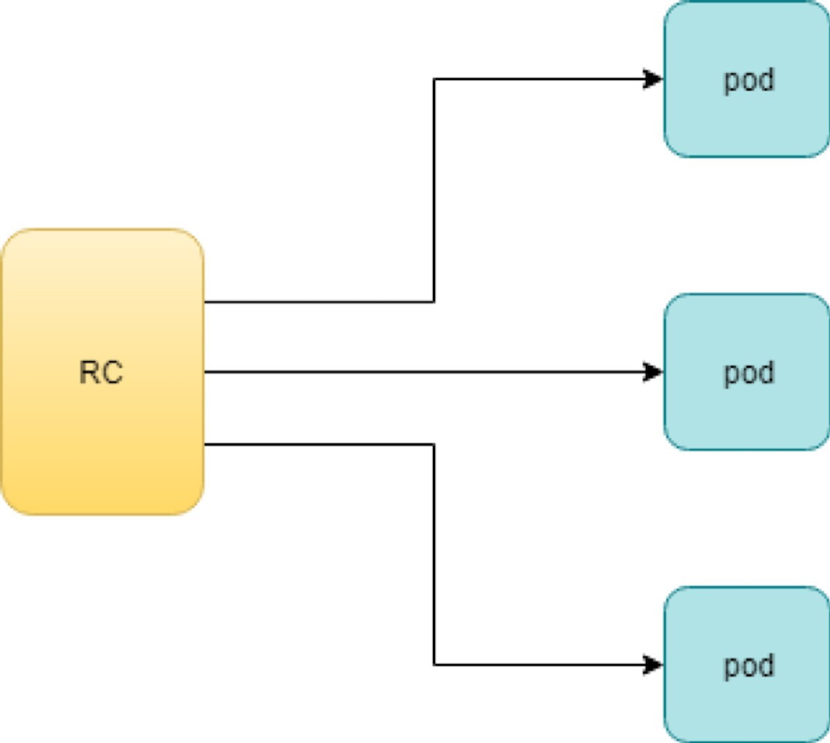
With the replicas parameter specified in the rc object YAML file, the Kubernetes replication controller, running as part of kube-controller-manager process in the master node, will keep monitoring the number of running pods spawned by the rc and automatically launch new ones should any of them run into failure. The key thing to learn is that individual pods may die any time, but the pool as a whole is always up and running, making a robust service. You will understand this better when you learn Kubernetes service.
Test Rc
You can test an rc’s impact by deleting one of the pods. To delete a resource with kubectl, use the kubectl delete sub-command:
$ kubectl delete pod webserver-5ggv6
pod "webserver-5ggv6" deleted
$ kubectl get pod
NAME	READY    STATUS	RESTARTS AGE
webserver-5ggv6  0/1		Terminating  0		22m		#<---
webserver-5v9w6  1/1			Running		0		2s	#<---
webserver-lbj89  1/1	Running	0		22m
webserver-m6nrx  1/1	Running	0	22m
$ kubectl get pod
NAME	READY    STATUS	RESTARTS AGE
webserver-5v9w6   1/1      Running      0		5s
webserver-lbj89   1/1      Running      0	22m
webserver-m6nrx   1/1      Running      0		22m
As you can see, when one pod is being terminated, a new pod is immediately spawned. Eventually the old pod will go away and the new pod will be up and running. The total number of running pods will remain unchanged.
You can also scale up or down replicas with rc. For example, to scale up from number of 3 to 5:
$ kubectl scale rc webserver --replica=5
replicationcontroller/webserver scaled


$ kubectl get pod
NAME	READY    STATUS	RESTARTS AGE
webserver-5v9w6  1/1		Running		0			8s
webserver-lbj89  1/1		Running		0			22m
webserver-m6nrx  1/1		Running		0			22m
webserver-hnnlj  0/1		ContainerCreating   0			2s
webserver-kbgwm  1/1		ContainerCreating   0			2s
$ kubectl get pod
NAME	READY    STATUS	RESTARTS AGE
webserver-5v9w6 	1/1		Running		0		10s
webserver-lbj89 	1/1		Running		0		22m
webserver-m6nrx 	1/1		Running		0		22m
webserver-hnnlj 	1/1		Running		0		5s
webserver-kbgwm 	1/1		Running		0		5s
There are other benefits with rc. Actually, since this abstraction is so popular and heavily used, two very similar objects, rs -ReplicaSet and Deploy – Deployment, have been developed with more powerful features. Generally speaking, you can call them next generation rc. For now, let’s stop exploring more rc features and move our focus to these two new objects.
Before moving to the next object, you can delete the rc:
$ kubectl delete rc webserver
replicationcontroller/webserver deleted
ReplicaSet
ReplicaSet, or rs object, is pretty much the same thing as an rc object, with just one major exception – the looks of selector:
#rs-webserver-do.yaml
apiVersion: apps/v1
kind: ReplicaSet metadata:
name: webserver

labels:
app: webserver
spec:
replicas: 3
selector:
matchLabels:	#<---
app: webserver	#<---
matchExpressions:	#<---
-	{key: app, operator: In, values: [webserver]} #<---
template:
metadata:
name: webserver
labels:

spec:
containers:
-	name: webserver
image: contrailk8sdayone/contrail-webserver
securityContext:
privileged: true


ports:
-	containerPort: 80webservercontrailK8sdayone
Rc uses equally-based selectors only, while rs supports an extra selector format, set-based. Functionally the two forms of selectors do the same job – that is—select the pod with a matching label:
#RS selector
matchLabels:
app: webserver
webserver
matchExpressions:
- {key: app, operator: In, values: [webserver]}

#RC selector
app: webserver
webserver
$ kubectl create -f rs-webserver.yaml
replicaset.extensions/webserver created
$ kubectl get pod
NAME	READY STATUS RESTARTS AGE
webserver-lkwvt	1/1     Running   0	8s
An rs is created and it launches a pod, just the same as what
an rc would do. If you compare the kubectl describe on the two objects:
$ kubectl describe rs webserver
......
Selector:     app=webserver,app in (webserver)	#<---
......
Type    Reason	Age  From	Message
......  ...... .... .... ......
Normal SuccessfulCreate 15s replicaset-controller Created pod: webserver-lkwvt
$ kubectl describe rc webserver
......
Selector:    app=webserver	#<---
......
Type    Reason	Age  From	Message
......  ...... .. . .... 	......
Normal SuccessfulCreate 19s replication-controller Created pod: webserver-lkwvt
As you can see, for the most part the outputs are the same, with the only exception of the selector format. You can also scale the rs the same way as you would do with rc:
$ kubectl scale rs webserver --replicas=5
replicaset.extensions/webserver scaled
$ kubectl get pod
NAME		READY 	STATUS 	RESTARTS 	AGE
webserver-4jvvx		1/1		Running 0		3m30s
webserver-722pf		1/1		Running 0		3m30s
webserver-8z8f8		1/1		Running 0		3m30s
webserver-lkwvt		1/1		Running 0		4m28s
webserver-ww9tn		1/1		Running 0		3m30s
Before moving to the next object, delete the rs:
$ kubectl delete rs webserver
replicaset.extensions/webserver deleted
Deployment
You may wonder why Kubernetes has different objects to do almost the same job. As mentioned earlier, the features of rc have been extended through the rs and deployment. We’ve seen the rs, which has done the same job of rc, only with a different selector format. Now we’ll check out the other new object, DEPLOY – deployment, and explore the features coming from it.
Create a Deployment
If you simply change the kind attribute from ReplicaSet to Deployment you’ll get the YAML file of a deployment object:
#deploy-webserver-do.yaml
apiVersion: apps/v1
kind: Deployment
metadata:
name: webserver
labels:
app: webserver
spec:
replicas: 1
selector:
matchLabels:
app: webserver
matchExpressions:
- {key: app, operator: In, values: [webserver]}
template:
metadata:
name: webserver
labels:
app: webserver
spec:
containers:
-	name: webserver
image: contrailk8sdayone/contrail-webserver
securityContext:
privileged: true
ports:
-	containerPort: 80
Create a deployment with the kubectl command:
.....
$ kubectl create -f deploy-webserver-do.yaml
deployment.extensions/webserver created

$ kubectl get deployment
NAME		DESIRED 	CURRENT 	UP-TO-DATE 	AVAILABLE AGE
deployment.apps/webserver  1		1		1		1		21s
.....
Actually, the deployment is a relatively higher-level of abstraction than rc and rs. Deployment does not create a pod directly, and the describe command reveals this:
$ kubectl describe deployments
Name:	webserver
Namespace:	default
CreationTimestamp:	Sat, 14 Sep 2019 23:17:17 -0400
Labels:	app=webserver
Annotations:		deployment.kubernetes.io/revision: 5
								kubectl.kubernetes.io/last-applied-configuration:
								{"apiVersion":"apps/v1","kind":"Deployment",
								"metadata":{"annotations":{},
								"labels":{"app":"webserver"},
								"name":"webserver","namespace":"defa...
Selector:	app=webserver,app in (webserver)
Replicas:	1 desired | 1 updated | 1 total | 1 available | 0 unavailable
StrategyType:		RollingUpdate
MinReadySeconds:	0
RollingUpdateStrategy: 25% max unavailable, 25% max surge
Pod Template:
Labels: app=webserver
Containers:
webserver:
Image:		contrailk8sdayone/contrail-webserver
Port:	80/TCP
Host Port: 0/TCP
Environment: <none>
Mounts:	<none>
Volumes:	<none>
Conditions:
Type		Status 	Reason
....		.....		......
Available		True 	MinimumReplicasAvailable
Progressing 	True 	NewReplicaSetAvailable
OldReplicaSets: <none>
NewReplicaSet: webserver-7c7c458cc5 (1/1 replicas created) #<---
Events:	<none>
Deployment Workflow
When you create a deployment a replica set is automatically created. The pods defined in the deployment object are created and supervised by the deployment’s replicaset.
The workflow is shown in Figure 2:
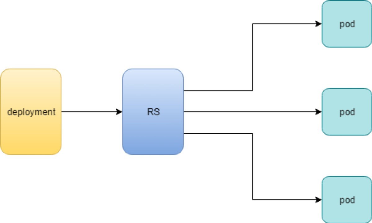
You might still be wondering why you need rs as one more layer sitting between deployment and pod and that’s answered next.
Rolling Update
The rolling update feature is one of the more powerful features that comes with the deployment object. Let’s demonstrate the feature with a test case to explain how it works.
In fact, a similar rolling update feature exists for the old rc object. The implementation has quite a few drawbacks compared with the new version supported by Deployment. In this book we focus on the new implementation with Deployment.
Test Case: Rolling Update
Suppose you have a nginx-deployment, with replica=3 and pod image 1.7.9. We want to upgrade the image
from version 1.7.9 to the new image version 1.9.1. With kuberctl you
can use the set image option and specify the new version number to
trigger the update:
$ kubectl set image deployment/nginx-deployment nginx=nginx:1.9.1
deployment.extensions/nginx-deployment image updated
Now check the deployment information again:
$ kubectl describe deployment/nginx-deployment
Name:	nginx-deployment
Namespace:	default
CreationTimestamp:	Tue, 11 Sep 2018 20:49:45 -0400
Labels:	app=nginx
Annotations:		deployment.Kubernetes.io/revision=2
Selector:	app=nginx
Replicas:	3 desired | 1 updated | 4 total | 3 available | 1 unavailable


StrategyType:	RollingUpdate
MinReadySeconds:		0
RollingUpdateStrategy: 25% max unavailable, 25% max surge
Pod Template:
Labels: app=nginx
Containers:
nginx:
Image:	nginx:1.9.1	#<------
Port:	80/TCP
Host Port: 0/TCP
Environment: <none>
Mounts:		<none>
Volumes:	<none>
Conditions:
Type		Status 	Reason
....		.....		.....
Available 	True	 MinimumReplicasAvailable
Progressing 	True 	ReplicaSetUpdated
OldReplicaSets: nginx-deployment-67594d6bf6 (3/3 replicas created)
NewReplicaSet: nginx-deployment-6fdbb596db (1/1 replicas created)
Events:
Type    	Reason		Age  From		Message
....			......		...		....	......
Normal ScalingReplicaSet 4m deployment-controller  Scaled up replica
set nginx-deployment-67594d6bf6 to 3 #<---
Normal ScalingReplicaSet 7s deployment-controller  Scaled up replica
set nginx-deployment-6fdbb596db to 1 #<---
There are two changes you can observe here:
The image version in deployment is updated
A new rs nginx-deployment-6fdbb596db is created, with a replica set to 1
And with the new rs with replica being 1, a new pod (the fourth one) is now generated:
$ kubectl get pods
NAME		READY    STATUS		RESTARTS 	AGE
nginx-deployment-67594d6bf6-88wqk   1/1		Running		0			4m
nginx-deployment-67594d6bf6-m4fbj   1/1		Running		0			4m
nginx-deployment-67594d6bf6-td2xn   1/1		Running		0			4m
nginx-deployment-6fdbb596db-4b8z7   0/1		ContainerCreating   0		17s	#<------
The new pod is with the new image:
$ kubectl describe pod/nginx-deployment-6fdbb596db-4b8z7 | grep Image:
...(snipped)...
Image:	nginx:1.9.1 #<---
...(snipped)...
While the old pod is still with the old image:
$ kubectl describe pod/nginx-deployment-67594d6bf6-td2xn | grep Image:
...(snipped)...


Image:	nginx:1.7.9 #<------
...(snipped)...
Let’s wait, and keep checking the pods status… eventually all old pods are terminated, and three new pods are running – the pod names confirm they are new ones:
$ kubectl get pods
NAME	READY     STATUS     RESTARTS  AGE
nginx-deployment-6fdbb596db-4b8z7   1/1       Running   0		1m
nginx-deployment-6fdbb596db-bsw25   1/1       Running   0		18s
nginx-deployment-6fdbb596db-n9tpg   1/1       Running   0		21s
So the update is done, and all pods are now running with the new version of the image.
How It Works
Hold on, you might argue, this is not updated, this should be called a replacement because Kubernetes used three new pods with new images to replace the old pods! Precisely speaking, this is true. But this is how it works. Kubernetes’s philosophy is that pods are cheap, and replacement is easy – imagine how much work it will be when you have to log in to each pod, uninstall old images, clean up the environment, only to install a new image. Let’s look at more details about this process and understand why it is called a rolling update.
When you update the pod with new software, the deployment object introduces a new rs that will start the pod update process. The idea here is not to log in to the existing pod and do the image update in -place, instead, the new rs just creates a new pod equipped with the new software release in it. Once this new (and additional) pod is up and running, the original rs will be scaled down by one, so the total number of running pods remains unchanged. The new rs will continue to scale up by one and the original rs scales down by one. This process repeats until the number of pods created by the new rs reaches the original replica number defined in the deployment, and that is when all of the original rs pods are terminated. The process is depicted in Figure 3.
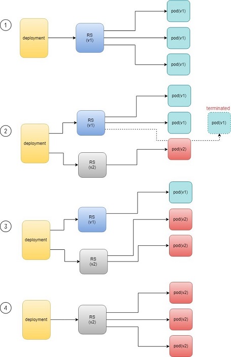
As you can see, the whole process of creating a new rs, scaling up the new rs, and scaling down the old one simultaneously, is fully automated and taken care of by the deployment object. It is deployment that is deploying and driving the ReplicaSet object, which, in this sense, is working merely as a backend.
This is why deployment is considered a higher-layer object in Kubernetes, and also the reason why it is officially recommended that you never use ReplicaSet alone, without deployment.
Record
Deployment also has the ability to record the whole process of rolling updates, so in case it is needed, you can review the update history after the update job is done:
$ kubectl describe deployment/nginx-deployment
Name:	nginx-deployment
...(snipped)...
NewReplicaSet: nginx-deployment-6fdbb596db (3/3 replicas created)
Events:
Type    Reason	Age  From	Message
Normal ScalingReplicaSet 28m deployment-controller Scaled up replica set nginx-deployment-67594d6bf6 to 3
Normal ScalingReplicaSet 24m deployment-controller Scaled up replica set nginx-deployment-6fdbb596db to 1
Normal ScalingReplicaSet 23m deployment-controller Scaled down replica set nginx-deployment-67594d6bf6 to 2
Normal ScalingReplicaSet 23m deployment-controller Scaled up replica set nginx-deployment-6fdbb596db to 2
Normal ScalingReplicaSet 23m deployment-controller Scaled down replica set nginx-deployment-67594d6bf6 to 1
Normal ScalingReplicaSet 23m deployment-controller Scaled up replica set nginx-deployment-6fdbb596db to 3
Normal ScalingReplicaSet 23m deployment-controller Scaled down replica set nginx-deployment-67594d6bf6 to 0
Pause/Resume/Undo
Additionally, you can also pause/resume the update process to verify the changes before proceeding:
$ kubectl rollout pause deployment/nginx-deployment
$ kubectl rollout resume deployment/nginx-deployment
You can even undo the update when things are going wrong during the maintenance window:
$ kubectl rollout undo deployment/nginx-deployment
$ kubectl describe deployment/nginx-deployment
Name:	nginx-deployment
...(snipped)...
NewReplicaSet: nginx-deployment-6fdbb596db (3/3 replicas created)
NewReplicaSet: nginx-deployment-67594d6bf6 (3/3 replicas created)
Events:
Type    Reason	Age From	Message
Normal DeploymentRollback 8m deployment-controller Rolled back deployment "nginx-deployment" to revision 1 #<------
Normal ScalingReplicaSet 8m deployment-controller Scaled up replica set nginx-deployment-67594d6bf6 to 1 #<------
Normal ScalingReplicaSet 8m deployment-controller Scaled down replica set nginx-deployment-6fdbb596db to 2 #<------
Normal  ScalingReplicaSet   8m  deployment-controller  Scaled up replica set nginx-deployment-67594d6bf6 to 2  #<------
Normal  ScalingReplicaSet   8m  deployment-controller  Scaled up replica set nginx-deployment-67594d6bf6 to 3  #<------
Normal  ScalingReplicaSet  8m  deployment-controller  Scaled down replica set nginx-deployment-6fdbb596db to 1 #<------
Normal  ScalingReplicaSet  8m  deployment-controller  Scaled down replica set nginx-deployment-6fdbb596db to 0 #<------
Typically you do this when something is broken in your deployment. Compared with how much work it takes to prepare for the software upgrade during maintenance windows in the old days, this is an amazing feature for anyone who suffered from software upgrade!
This is pretty similar to the Junos rollback magic command that you probably use every day when you need to quickly revert the changes you make to your router.
Secrets
All modern network systems need to deal with sensitive information, such as username, passwords, SSH keys, etc. in the platform. The same applies to the pods in a Kubernetes environment. However, exposing this information in your pod specs as cleartext may introduce security concerns and you need a tool or method to resolve the issue – at least to avoid the cleartext credentials as much as possible.
The Kubernetes secrets object is designed specifically for this purpose – it encodes all sensitive data and exposes it to pods in a controlled way.
The official definition of Kubernetes secrets is:
"A Secret is an object that contains a small amount of sensitive data such as a password, a token, or a key. Such information might otherwise be put in a Pod specification or in an image; putting it in a secret object allows for more control over how it is used and reduces the risk of accidental exposure."
Users can create secrets, and the system also creates secrets. To use a secret, a pod needs to reference the secret.
There are many different types of secrets, each serving a specific use case, and there are also many methods to create a secret and a lot of different ways to refer to it in a pod. A complete discussion of secrets is beyond the scope of this book, so please refer to the official documentation to get all of the details and track all up-to-date changes.
Here, we’ll look at some commonly used secret types. You will also learn several methods to create a secret and how to refer to it in your pods. And once you get to the end of the section, you should understand the main benefits of a Kubernetes secrets object and how it can help improve your system security.
Let’s begin with a few secret terms:
Opaque: This type of secret can contain arbitrary key-value pairs, so it is treated as unstructured data from Kubernetes’ perspective. All other types of secret have constant content.
Kubernetes.io/Dockerconfigjson: This type of secret is used to authenticate with a private container registry (for example, a Juniper server) to pull your own private image.
TLS: A TLS secret contains a TLS private key and certificate. It is used to secure an ingress. You will see an example of an ingress with a TLS secret in Chapter 4.
Kubernetes.io/service-account-token: When processes running in containers of a pod access the API server, they have to be authenticated as a particular account (for example, account default by default). An account associated with a pod is called a service-account. Kubernetes.io/service-account-token type of secret contains information about Kubernetes service-account. We won’t elaborate on this type of secret and service-account in this book.
Opaque secret: The secret of type opaque represents arbitrary user-owned data – usually you want to put some kind of sensitive data in secret, for example, username, password, security pin, etc., just about anything you believe is sensitive and you want to carry into your pod.
Define Opaque Secret
First, to make our sensitive data looks less sensitive, let’s encode it with the base64 tool:
$ echo -n 'username1' | base64
dXNlcm5hbWUx
$ echo -n 'password1' | base64
cGFzc3dvcmQx
Then put the encoded version of the data in a secret definition YAML file:
apiVersion: v1
kind: Secret
metadata:
name: secret-opaque
type: Opaque
data:
username: dXNlcm5hbWUx
password: cGFzc3dvcmQx
Alternatively, you can define the same secret from kubectl CLI directly, with the --from-literal option:
kubectl create secret generic secret-opaque    \
--from-literal=username='username1'	\
--from-literal=password='password1'
Either way, a secret will be generated:
$ kubectl get secrets
NAME	TYPE	DATA AGE
secret-opaque	Opaque	2	8s

$ kubectl get secrets secret-opaque -o yaml
apiVersion: v1
data:
password: cGFzc3dvcmQx
username: dXNlcm5hbWUx
kind: Secret
metadata:
annotations:
kubectl.kubernetes.io/last-applied-configuration: |
{"apiVersion":"v1","data":{"password":"cGFzc3dvcmQx","username":"dXNlcm5hbWUx"},"kind":"Secret","metadata":{"annotations":{},"name"
:"secret-opaque","namespace":"ns-user-1"},"type":"Opaque"}
creationTimestamp: 2019-08-22T22:51:18Z
name: secret-opaque
namespace: ns-user-1
resourceVersion: "885702"
selfLink: /api/v1/namespaces/ns-user-1/secrets/secret-opaque


uid: 5a78d9d4-c52f-11e9-90a3-0050569e6cfc
type: Opaque
Refer Opaque Secret
Next you will need to use the secret in a pod, and the user information contained in the secret will be carried into the pod. As mentioned, there are different ways to refer the opaque secret in a pod, and correspondingly, the result will be different.
Typically, user information carried from a secret can appear in a container in one of these forms:
Files
Environmental variables
Now let’s demonstrate using secret to generate environmental variables in a container:
#pod-webserver-do-secret.yaml
apiVersion: v1
kind: Pod
metadata:
name: contrail-webserver-secret
labels:
app: webserver
spec:
containers:
- name: contrail-webserver-secret
image: contrailk8sdayone/contrail-webserver
#envFrom:
#- secretRef:
# name: test-secret
env:
- name: SECRET_USERNAME
valueFrom:
secretKeyRef:
name: secret-opaque
key: username
- name: SECRET_PASSWORD
valueFrom:
secretKeyRef:
name: secret-opaque
key: password
Spawn the pod and container from this YAML file:
$ kubectl apply -f pod/pod-webserver-do-secret.yaml
pod/contrail-webserver-secret created
Log in the container and verify the generated environmental variables:
$ kubectl exec -it contrail-webserver-secret -- printenv | grep
SECRET SECRET_USERNAME=username1
SECRET_PASSWORD=password1
The original sensitive data encoded with base64 is now present in the container!
Dockerconfigjson Secret
The dockerconfigjson secret, as the name indicates, carries the Docker account credential information that is typically stored in a .docker/config.json file. The image in a Kubernetes pod may point to a private container registry. In that case, Kubernetes needs to authenticate it with that registry in order to pull the image. The dockerconfigjson type of secret is designed for this very purpose.
Docker Credential Data
The most straightforward method to create a kubernetes.io/dockerconfigjson type of secret is to provide login information directly with the kubectl command and let it generate the secret:
$ kubectl create secret docker-registry secret-jnpr1 \
--docker-server=hub.juniper.net	\
--docker-username=JNPR-FieldUser213	\
--docker-password=CLJd2kpMsVc9zrAuTFPn
secret/secret-jnpr created
Verify the secret creation:
$ kubectl get secrets
NAME	TYPE	DATA AGE
secret-jnpr	kubernetes.io/dockerconfigjson	1		6s #<---
default-token-hkkzr   kubernetes.io/service-account-token   3		62d
Only the first line in the output is the secret you have just created. The second line is a kubernetes.io/service-account-token type of secret that the Kubernetes system creates automatically when the contrail setup is up and running.
Now inspect the details of the secret:
$ kubectl get secrets secret-jnpr -o yaml
apiVersion: v1
data:
.dockerconfigjson: eyJhdXRocyI6eyJodWIuanVuaXBlci5uZXQvc2...<snipped>...
kind: Secret
metadata:
creationTimestamp: 2019-08-14T05:58:48Z
name: secret-jnpr
namespace: ns-user-1
resourceVersion: "870370"
selfLink: /api/v1/namespaces/ns-user-1/secrets/secret-jnpr
uid: 9561cdc3-be58-11e9-9367-0050569e6cfc
type: kubernetes.io/dockerconfigjson
Not surprisingly, you don’t see any sensitive information in the form of cleartext. There is a data portion of the output where you can see a very long string as the value of key: dockerconfigjson. Its appearance seems to have transformed from the original data, but at least it does not contain sensitive information anymore – after all one purpose of using a secret is to improve the system security.
However, the transformation is done by encoding, not encryption, so there is still a way to manually retrieve the original sensitive information: just pipe the value of key .dockerconfigjson into the base64 tool, and the original username and password information is viewable again:
$ echo "eyJhdXRocyI6eyJodWIuanVua..." | base64 -d | python -mjson.tool
{
		"auths": {
			"hub.juniper.net": {
						"auth": "Sj5QUi1GaWVsZFVzZXIyMTM6Q0xKZDJqcE1zVmM5enJBdVRGUG4=",
						"password": "CLJd2kpMsVc9zrAuTFPn", "username": "JNPR-FieldUser213"
			}
		}
}
Some highlights in this output are:
The python -mjson.tool is used to format the decoded json data before displaying to the terminal.
There is an auth key-value pair. It is the token generated based on the authentication information you gave (username and password).
Later on, when equipped with this secret, a pod will use this token, instead of the username and password to authenticate itself towards the private Docker registry hub.juniper.net in order to pull a Docker image.
Here’s another way to decode the data directly from the secret object:
$ kubectl get secret secret-jnpr1 \
--output="jsonpath={.data.\.dockerconfigjson}" \
| base64 --decode | python -mjson.tool
{
			"auths": {
					"hub.juniper.net/security": {
							"auth": "Sj5QUi1GaWVsZFVzZXIyMTM6Q0xKZDJqcE1zVmM5enJBdVRGUG4=",
							"password": "CLJd2kpMsVc9zrAuTFPn", "username": "JNPR-FieldUser213"
					}
			}
}
The --output=xxxx option filters
the kubectl get output so only the value of .dockerconfigjson under
data is displayed. The value is then piped into base64 with option
--decode (alias of -d) to get it decoded.
A docker-registry secret created manually like this will only work with a single private registry. To support multiple private container registries you can create a secret from the Docker credential file.
Docker Credential File (~/.Docker/config.json)
As the name of the key .dockerconfigjson in the secret we created indicates, it serves a similar role as the Docker config file: .docker/config.json. Actually, you can generate the secret directly from the Docker configuration file.
To generate the Docker credential information, first check the Docker config file:
$ cat .docker/config.json
{
......
"auths": {},
......
}
There’s nothing really here. Depending on the usage of the set up you may see different output, but the point is that this Docker config file will be updated automatically every time you docker login a new registry:
$ cat mydockerpass.txt | \
	docker login hub.juniper.net \
		--username JNPR-FieldUser213 \
		--password-stdin
Login Succeeded
The file mydockerpass.txt is the login password for username JNPR-FieldUser213. Saving the password in a file and then piping it to the docker login command with --password-stdin option has an advantage of not exposing the password cleartext in the shell history.
If you want you can write the password directly, and you will get a friendly warning that this is insecure.
$ docker login hub.juniper.net --username XXXXXXXXXXXXXXX --password XXXXXXXXXXXXXX
WARNING! Using --password via the CLI is insecure. Use --password-stdin.
Login Succeeded
Now the Docker credential information is generated in the updated config.json file:
$ cat .docker/config.json
{
......
		"auths": { #<---
				"hub.juniper.net": {
				"auth": "Sj5QUi1GaWVsZFVzZXIyMTM6Q0xKZDJqcE1zVmM5enJBdVRGUG4="
				}
		},
......
}
The login process creates or updates a config.json file that holds the authorization token. Let’s create a secret
from the .docker/config.json file:
$ kubectl create secret generic secret-jnpr2 \
--from-file=.dockerconfigjson=/root/.docker/config.json \
--type=kubernetes.io/dockerconfigjson
secret/secret-jnpr2 created

$ kubectl get secrets


NAME	TYPE	DATA AGE
secret-jnpr2 kubernetes.io/dockerconfigjson 1 8s #<--- default-token-
hkkzr kubernetes.io/service-account-token 3 63d secret-jnpr
	kubernetes.io/dockerconfigjson 1 26m
$ kubectl get secrets secret-jnpr2 -o yaml
apiVersion: v1
data:
.dockerconfigjson: ewoJImF1dGhzIjoIlNrNVFVaTFHYVdWc1pGVnpaWEl5TVRNNlEweEtaREpxY0UxelZtTTVlbkpCZ
FZSR1VHND0iCgkJfQoJfSwKCSJIdHRwSGVhZGVycyI6IHsKCQkiVXNlci1BZ2VudCI6ICJEb2NrZXItQ2xpZW50LzE4LjAzLjE
tY2UgKGxpbnV4KSIKCX0sCgkiZGV0YWNoS2V5cyI6ICJjdHJsLUAiCn0=
kind: Secret
metadata:
creationTimestamp: 2019-08-15T07:35:25Z
name: csrx-secret-dr2
namespace: ns-user-1
resourceVersion: "878490"
selfLink: /api/v1/namespaces/ns-user-1/secrets/secret-jnpr2
uid: 3efc3bd8-bf2f-11e9-bb2a-0050569e6cfc
type: kubernetes.io/dockerconfigjson

$ kubectl get secret secret-jnpr2 --output="jsonpath={.data.\.dockerconfigjson}" | base64 --decode
{
......
			"auths": { "hub.juniper.net": {
					"auth": "Sj5QUi1GaWVsZFVzZXIyMTM6Q0xKZDJqcE1zVmM5enJBdVRGUG4="
			}
					},
......
}
YAML File
You can also create a secret directly from a YAML file the same way you create other objects like service or ingress.
To manually encode the content of the .docker/config.json file:
$ cat .docker/config.json | base64
ewoJImF1dGhzIjogewoJCSJodWIuanVuaXBlci5uZXQiOiB7CgkJCSJhdXRoIjogIlNrNVFVaTFH
YVdWc1pGVnpaWEl5TVRNNlEweEtaREpxY0UxelZtTTVlbkpCZFZSR1VHND0iCgkJfQoJfSwKCSJI
dHRwSGVhZGVycyI6IHsKCQkiVXNlci1BZ2VudCI6ICJEb2NrZXItQ2xpZW50LzE4LjAzLjEtY2Ug
KGxpbnV4KSIKCX0sCgkiZGV0YWNoS2V5cyI6ICJjdUAiCn0=
Then put the base64 encoded value of the .docker/config.json file as data in below the YAML file:
#secret-jnpr.yaml
apiVersion: v1
kind: Secret
type: kubernetes.io/dockerconfigjson
metadata:
	name: secret-jnpr3
	namespace: ns-user-1
data:
.dockerconfigjson: ewoJImF1dGhzIjogewoJCSJodW......
$ kubectl apply -f secret-jnpr.yaml
secret/secret-jnpr3 created


$ kubectl get secrets
NAME	TYPE	DATA AGE
default-token-hkkzr   kubernetes.io/service-account-token   3		64d
secret-jnpr1	kubernetes.io/dockerconfigjson	1		9s
secret-jnpr2	kubernetes.io/dockerconfigjson	1		6m12s
secret-jnpr3	kubernetes.io/dockerconfigjson	1		78s
Keep in mind that base64 is all about encoding instead of encryption – it is considered the same as plain text. So sharing this file compromises the secret.
Refer Secret in Pod
After a secret is created, it can be referred to by a pod/rc or deployment in order to pull an image from the private registry. There are many ways to refer to secrets. This section will examine using imagePullSecrets under pod spec to refer to the secret.
An imagePullSecret is a way to pass a secret that contains a Docker (or other) image registry password to the kubelet so it can pull a private image on behalf of your pod.
Create a pod pulling the Juniper cSRX container from the private repository:
apiVersion: v1
kind: Pod
metadata:
	name: csrx-jnpr
labels:
app: csrx
annotations:
k8s.v1.cni.cncf.io/networks: '[
{ "name": "vn-left-1" },
{ "name": "vn-right-1" }
]'
spec:
containers:
#- name: csrx
# image: csrx
-	name: csrx
image: hub.juniper.net/security/csrx:18.1R1.9
ports:
-	containerPort: 22
#imagePullPolicy: Never
imagePullPolicy: IfNotPresent
stdin: true
tty: true
securityContext:
privileged: true
imagePullSecrets:
-	name: secret-jnpr
Now, generate the pod:
$ kubectl apply -f csrx/csrx-with-secret.yaml
pod/csrx-jnpr created
The cSRX is up and running:
$ kubectl get pod
NAME	READY STATUS RESTARTS AGE
csrx-jnpr		1/1     Running   0		20h
And behind the scenes, the pod authenticates itself towards the private registry, pulls the image, and launches the cSRX container:
$ kubectl describe pod csrx
......
Events:
19h Normal Scheduled Pod Successfully assigned ns-user-1/csrx to cent333
19h Normal Pulling Pod pulling image "hub.juniper.net/security/csrx:18.1R1.9"
19h Normal Pulled Pod  Successfully pulled image "hub.juniper.net/security/csrx:18.1R1.9"
19h Normal Created Pod Created container
19h Normal Started Pod Started container
As you saw from our test, the secret objects are created independently of the pods, and inspecting the object spec does not provide the sensitive information directly on the screen.
Secrets are not written to the disk, but are instead stored in a tmpfs file system, only on nodes that need them. Also, secrets are deleted when the pod that is dependent on them is deleted.
On most native Kubernetes distributions, communication between users and the API server is protected by SSL/TLS. Therefore, secrets transmitted over these channels are properly protected.
Any given pod does not have access to the secrets used by another pod, which facilitates encapsulation of sensitive data across different pods. Each container in a pod has to request a secret volume in its volumeMounts for it to be visible inside the container. This feature can be used to construct security partitions at the pod level.
Service
When a pod gets instantiated, terminated, and moved from one node to another, and in so doing changes its IP address, how do we keep track of that to get uninterrupted functionalities from the pod? Even if the pod isn’t moving, how does traffic reach groups of pods via a single entity?
The answer to both questions is Kubernetes service.
Service is an abstraction that defines a logical set of pods and a policy, by which you can access them. Think of services as your waiter in a big restaurant – this waiter isn’t cooking, instead he’s an abstraction of everything happing in the kitchen and you only have to deal with this single waiter.
Service is a Layer 4 load balancer and exposes pod functionalities via a specific IP and port. The service and pods are linked via labels like rs. And there’s three different types of services:
ClusterIP
NodePort
LoadBalancer
ClusterIP Service
The clusterIP service is the simplest service, and the default mode if the ServiceType is not specified. Figure 4 illustrates how clusterIP service works.
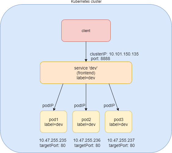
You can see that the ClusterIP Service is exposed on a clusterIP and a service port. When client pods need to access the service it sends requests towards this clusterIP and service port. This model works great if all requests are coming from inside of the same cluster. The nature of the clusterIP limits the scope of the service to only be within the cluster. Overall, by default, the clusterIP is not externally reachable .
Create ClusterIP Service
#service-web-clusterip.yaml
apiVersion: v1
kind: Service
metadata:
name: service-web-clusterip


spec:
ports:
- port: 8888
targetPort: 80
selector:
app: webserver
The YAML file looks pretty simple and self-explanatory. It defines
a service/service-web-clusterip with the
service port 8888, mapping to targetPort, which means container port
80 in some pod. The selector indicates that whichever pod with a label
and app: webserver will be the backend pod responding service request.
Okay, now generate the service:
$ kubectl apply -f service-web-clusterip.yaml
service/service-web-clusterip created
Use kubectl commands to quickly verify
the service and backend pod objects:
$ kubectl get svc -o wide
NAME	TYPE	CLUSTER-IP	EXTERNAL-IP PORT(S) AGE SELECTOR
service-web-clusterip  ClusterIP 10.101.150.135 <none>	8888/TCP 9m10s app=webserver

$ kubectl get pod -o wide -l 'app=webserver'
No resources found.
The service is created successfully, but there are no pods for the service. This is because there is no pod with a label matching the selector in the service. So you just need to create a pod with the proper label.
Now, you can define a pod directly but given the benefits of rc and the deployment over pods, as discussed earlier, using rc or deployment is more practical (you’ll soon see why).
As an example, let’s define a Deployment object named webserver:
#deploy-webserver-do.yaml
apiVersion: apps/v1
kind: Deployment
metadata:
name: webserver
labels:
app: webserver
spec:
replicas: 1
selector:
matchLabels:
app: webserver
matchExpressions:
	- {key: app, operator: In, values: [webserver]} template:
metadata:
	name: webserver
	labels:
		app: webserver
spec:
	containers:
	-	name: webserver


image: contrailk8sdayone/contrail-webserver
securityContext:
	privileged: true
	ports:
		-	containerPort: 80
The Deployment webserver has a label app: webserver, matching
the selector defined in our service. The replicas: 1 instructs the controller to launch only
one pod at the moment. Let’s see:
$ kubectl apply -f deployment-webserver-do.yaml
deployment.extensions/webserver created

$ kubectl get pod -o wide -l 'app=webserver'
NAME	READY  STATUS    RESTARTS AGE IP	NODE NOMINATED NODE
webserver-7c7c458cc5-vl6zs  1/1   Running 0	24s 10.47.255.238 cent333 <none>
And immediately the pod is chosen to be the backend.
Other brief summaries about the previous kubectl
get svc command output are:
The service got a clusterIP, or service IP, of 10.101.150.135 allocated from the service IP pool.
The service port is 8888 as what is defined in YAML.
By default, the protocol type is TCP if not declared in the YAML file. You can use protocol: UDP to declare a UDP service.
The backend pod can be located with the label selector.
The example shown here uses an equality-based selector
(-l) to locate the backend pod, but you can also use a set-based syntax
to archive the same effect. For example: kubectl get
pod -o wide -l 'app in (webserver)'.
Verify ClusterIP Service
To verify that the service actually works, let’s start another pod as a client to initiate a HTTP request toward the service. For this test, we’ll launch and log in to a client pod and use the curl command to send an HTTP request toward the service. You’ll see the same pod being used as a client to send requests throughout this book:
#pod-client-do.yaml
apiVersion: v1
kind: Pod
metadata:
	name: client
	labels:
		app: client
spec:
	containers:
	- name: contrail-webserver
	image: contrailk8sdayone/contrail-webserver
Create the client pod:
$ kubectl apply -f pod-client-do.yaml
pod/client created
The client pod is just another spawned pod based on the exact same image whatever the webserver Deployment and its pods do. This is the same as with physical servers and VMs: nothing stops a server from doing the client’s job:
$ kubectl exec -it client -- curl 10.101.150.135:8888
<html>
<style>
h1 {color:green}
h2 {color:red}
</style>
<div align="center">
<head>
<title>Contrail Pod</title>
</head>
<body>
<h1>Hello</h1><br><h2>This page is served by a <b>Contrail</b>
pod</h2><br><h3>IP address = 10.47.255.238<br>Hostname =
webserver-7c7c458cc5-vl6zs</h3>
<img src="/static/giphy.gif">
</body>
</div>
</html>
The HTTP request toward the service reaches a backend pod running the web server application, which responds with a HTML page.
To better demonstrate which pod is providing the service, let’s set up a customized pod image that runs a simple web server. The web server is configured in such a way that when receiving a request it will return a simple HTML page with local pod IP and hostname embedded. This way the curl returns something more meaningful in our test.
The returned HTML looks relatively okay to read, but there is a way to make it easier to see, too:
$ kubectl exec -it client -- curl 10.101.150.135:8888 | w3m -T text/html | head
																		Hello
This page is served by a Contrail pod
			IP address = 10.47.255.238
			Hostname = webserver-7c7c458cc5-vl6zs
The w3m tool is a lightweight console-based web browser installed in the host. With w3m you can render a HTML webpage into text, which is more readable than the HTML page.
Now that service is verified, requests to service have been redirected to the correct backend pod, with a pod IP of 10.47.255.238 and a pod name of webserver-7c7c458cc5-vl6zs.
Specify a ClusterIP
If you want to have a specific clusterIP, you can mention it in the spec. IP addresses should be in the service IP pool.
Here’s some sample YAML with specific clusterIP:
#service-web-clusterip-static.yaml
apiVersion: v1
kind: Service
metadata:
	name: service-web-clusterip-static
	spec:
	clusterIP: 10.101.150.150	#<---
	ports:
		- port: 8888
		targetPort: 80
selector:
app: webserver
NodePort Service
The second general type of service, NodePort, exposes a service on each node’s IP at a static port. It maps the static port on each node with a port of the application on the pod as shown in Figure 5.
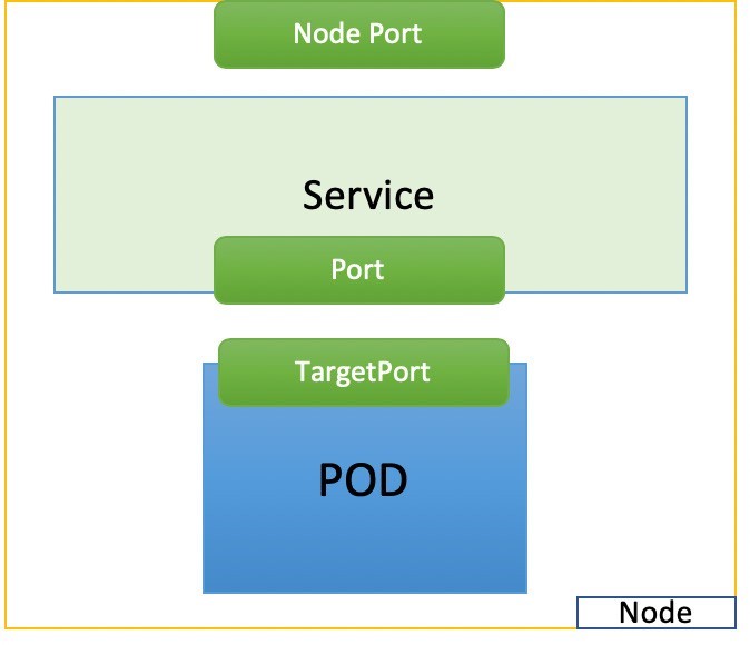
#service-web-nodeport
apiVersion: v1
kind: Service
metadata:
	name: service-web-nodeport
spec:
	selector:
	app: webserver
type: NodePort
ports:
	- targetPort: 80
	port: 80
	nodePort: 32001 #<--- (optional)
Here are some highlights in this services YAML file:
selector: The label selector that determines which set of pods is targeted by this service; here, any pod with the label app: webserver will be selected by this service as the backend.Port: This is the service port.TargetPort: The actual port used by the application in the container. Here, it’s port 80, as we are planning to run a web server.NodePort: The port on the host of each node in the cluster.
Let’s create the service:
$ kubectl create -f service-web-nodeport.yaml
service "service-web-nodeport" created

$ kubectl describe service web-app
Name:	service-web-nodeport
Namespace:	default
Labels:	<none>
Annotations:	<none>
Selector:	app=webserver
Type:	NodePort
IP:	10.98.108.168
Port:	<unset> 80/TCP
TargetPort:	80/TCP
NodePort:	<unset> 32001/TCP
Endpoints:	10.47.255.228:80
Session Affinity:		None External Traffic Policy: Cluster
Events:	<none>
Type: The default service type is
ClusterIP. In this example, we set the type toNodePort.NodePort: By default, Kubernetes allocates node ports in the 30000-32767 range, if it is not mentioned in the spec. This can be changed using the flag--service-node-port-range. TheNodePortvalue can also be set, but make sure it’s in the configured rangeEndpoints: The podIP and the exposed container port. The request toward service IP and service port will be directed here, and 10.47.255.252:80 indicates that we have created a pod that has a matching label with the service, so its IP is selected as one of the backends.
For this test, make sure there is at least one pod with
the label app:webserver running. Pods in
previous sections are all created with this label. Recreating the
client pod suffices if you’ve removed them already.
Now we can test this by using the curl command to trigger an HTTP request toward any node IP address:
$kubectl get pod -o wide

NAME    READY   STATUS     RESTARTS  AGE  IP	NODE	NOMINATED NODE
client  1/1     Running   0	20m 10.47.255.252 cent222 <none>
With the power of the NodePort service, you can access the web server running in the pod from any node via the nodePort 32001:
$ kubectl get node -o wide
NAME	STATUS      ROLES    AGE    VERSION   INTERNAL-IP  ... KERNEL-VERSION	CONTAINER-RUNTIME


cent111 NotReady master 100d v1.12.3 10.85.188.19 ... 3.10.0-957.10.1.el7.x86_64 docker://18.3.1  cent222
Ready <none>  100d  v1.12.3  10.85.188.20  ... 3.10.0-957.10.1.el7.x86_64  docker://18.3.1 cent333 Ready
<none> 100d v1.12.3 10.85.188.21 ... 3.10.0-957.10.1.el7.x86_64 docker://18.3.1

$ curl 10.85.188.20:32001

<html>
<style>
h1 {color:green}
h2 {color:red}
</style>
<div align="center">
<head>
<title>Contrail Pod</title>
</head>
<body>
<h1>Hello</h1><br><h2>This page is served by a <b>Contrail</b>
pod</h2><br><h3>IP address = 10.47.255.228<br>Hostname
= client</h3>
<img src="/static/giphy.gif">
</body>
</div>
</html>
Load Balancer Service
The third service, the load balancer service, goes one step beyond the NodePort service by exposing the service externally using a cloud provider’s load balancer. The load balancer service by its nature automatically includes all the features and functions of NodePort and ClusterIP services.
Kubernetes clusters running on cloud providers support the automatic provision of a load balancer. The only difference between the three services is the type value. To reuse the same NodePort service YAML file, and create a load balancer service, just set the type to LoadBalancer:
#service-web-lb.yaml
apiVersion: v1
kind: Service
metadata:
	name: service-web-lb
spec:
	ports:
		- port: 8888
		targetPort: 80
selector:
	app: webserver
type: LoadBalancer #<---
The cloud will see this keyword and a load balancer will be created. Meanwhile, an external public load balancerIP is allocated to serve as the frontend virtual IP. Traffic coming to this loadbalancerIP will be redirected to the service backend pod. Please keep in mind that this redirection process is solely a transport layer operation. The loadbalancerIP and port will be translated to private backend clusterIP and it’s targetPort. It does not involve any application layer activities. There is nothing like parsing a URL, proxy HTTP request, and etc., like what happens in the HTTP proxying process. Because the loadbalancerIP is publicly reachable, any Internet host that has access to it (and the service port) can access the service provided by the Kubernetes cluster.
From an Internet host’s perspective, when it requests service, it refers this public external loadbalancerIP plus service port, and the request will reach the backend pod. The loadbalancerIP is acting as a gateway between service inside of the cluster and the outside world.
Some cloud providers allow you to specify the loadBalancerIP. In those cases, the load balancer is created with the user-specified
loadBalancerIP. If the loadBalancerIP field is not specified, the
load balancer is set up with an ephemeral IP address. If you specify
a loadBalancerIP but your cloud provider does not support the feature,
the loadbalancerIP field that you set is ignored.
How a load balancer is implemented in the load balancer service is vendor-specific. A GCE load balancer may work in a totally different way with an AWS load balancer. There is a detailed demonstration of how the load balancer service works in a Contrail Kubernetes environment in Chapter 4.
External IPs
Exposing service outside of the cluster can also be achieved
via the externalIPs option. Here’s
an example:
#service-web-externalips.yaml
apiVersion: v1
kind: Service
metadata:
	name: service-web-externalips
spec:
	ports:
		- port: 8888
		targetPort: 80
selector:
	app: webserver
externalIPs:	#<---
- 101.101.101.1	#<---
In the Service spec, externalIPs
can be specified along with any of the service types. External IPs
are not managed by Kubernetes and are the responsibility of the cluster
administrator.
External IPs are different from loadbalancerIP, which is the IP assigned by the cluster administrator, while external IPs come with the load balancer created by the cluster that supports it.
Service Implementation: Kube-proxy
By default, Kubernetes uses the kube-proxy module for services, but CNI providers can have their own implementations for services.
Kube-proxy can be deployed in one of the three modes:
user-space proxy-mode
iptables proxy-mode
ipvs proxy-mode
When traffic hits the node, it’s forwarded to one of the backend pods via a deployed kube-proxy forwarding plane. Detailed explanations and comparisons of these three modes will not be covered in this book, but you can check Kubernetes official website for more information. Chapter 4 illustrates how Juniper Contrail as a Container Network Interface (CNI) provider implements the service.
Endpoints
There is one object we haven’t explored so far: EP, or endpoint. We’ve learned that a particular pod or group of pods with matching labels are chosen to be the backend through label selector, so the service request traffic will be redirected to them. The IP and port information of the matching pods are maintained in the endpoint object. The pods may die and spawn any time, the mortal nature of the pod will most likely cause the new pods be respawned with new IP addresses. During this dynamic process the endpoints will always be updated accordingly, to reflect the current backend pod IPs, so the service traffic redirection will act properly. (CNI providers who have their own service implementation update the backend of the service based on the endpoint objects.)
Here is an example to demonstrate some quick steps to verify the service, corresponding endpoint, and the pod, with matching labels.
To create a service:
#service-web-clusterip.yaml
apiVersion: v1
kind: Service
metadata:
	name: service-web-clusterip
spec:
	ports:
		- port: 8888
		targetPort: 80
selector:
	app: webserver

$kubectl apply -f service-web-clusterip.yaml
service/service-web-clusterip created
To list the endpoint:
To locate the pod with the label that is used by the selector in service:
And finally, scale the backend pods:
Now check the endpoints again, and you will see that they are updated accordingly:
Service Without Selector
In the preceding example, the endpoints object is automatically generated by the Kubernetes system whenever a service is created and at least one pod with a matching label exists. But another endpoint use case is a service that has no label selector defined in which you can manually map the service to the network address and the port where it’s running by manually adding an endpoint object. Then you can connect the endpoint with the service. This can be very useful in some scenarios, for example, in a setup where you have a backend web server running in a physical server, and you still want to integrate it into a Kubernetes service. In that case, you just create the service as usual, and then create an endpoint with an address and port pointing to the web server. That’s it! The service does not care about the backend type, it just redirects the service request traffic exactly the same way as if all backend is a pod.
Ingress
Now that you’ve now seen ways of exposing a service to clients outside the cluster, another method is Ingress. In the service section, service works in transport layer. In reality, you access all services via URLs.
Ingress, or ing for short, is another core concept of Kubernetes that allows HTTP/HTTPS routing that does not exist in service. Ingress is built on top of service. With ingress, you can define URL-based rules to distribute HTTP/HTTPS routes to multiple different backend services, therefore, ingress exposes services via HTTP/HTTPS routes. After that the requests will be forwarded to each service’s corresponding backend pods.
Ingress Versus Service
There are similarities between load balancer service and ingress. Both can expose service outside of the cluster, but there are some significant differences.
Operation Layer
Ingress operates at the application layer of the OSI network model, while service only operates at the transport layer. Ingress understands the HTTP/HTTPS protocol, service only enacts forwarding based on the IP and the port, which means it does not care about the application layer protocol (HTTP/HTTPS) details. Ingress can operate at the transport layer, but service does the same thing, so it doesn’t make sense for ingress to do it as well, unless there is a special reason to do so.
Forwarding Mode
Ingress does the application layer proxy pretty much in the same way a traditional web load balancer does. A typical web load balancer proxy sitting between machine A (client) and B (server), works at the application layer. It is aware of the application layer protocols (HTTP/HTTPS) so the client-server interaction does not look transparent to the load balancer. Basically it creates two connections each with the source, (A), and the destination, (B), machine. Machine A does not even know about the existence of machine B. For machine A, the proxy is the only thing it talks to and it does not care how and where the proxy gets its data.
Number of Public IPs.
Each service of the ingress needs a public IP if it is exposed directly to the outside of the cluster. When ingress is a frontend to all these services, one public IP is sufficient, which makes life easy for cloud administrators.
Ingress Object
Before going into detail about the ingress object, the best way to get a feel for it is to look at the YAML definition:
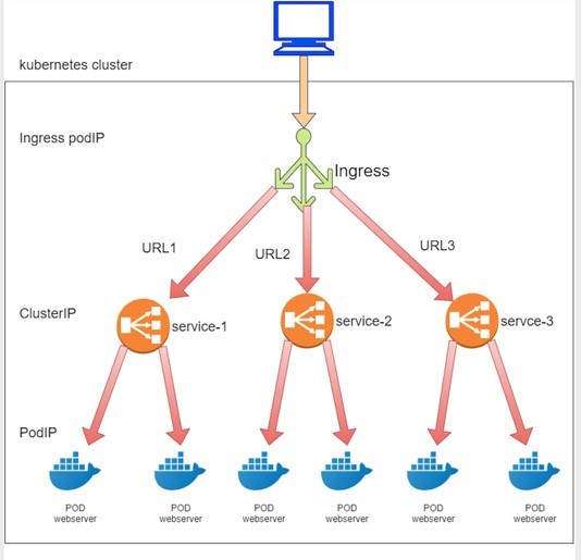
apiVersion: extensions/v1beta1
kind: Ingress
metadata:
	name: ingress-sf
spec:
	rules:
		-	host: www.juniper.net
	http:
		paths:
		-	path: /dev
		backend:
		serviceName: webservice-1
		servicePort: 8888
	-	path: /qa
		backend:
			serviceName: webservice-2
			servicePort: 8888
You can see it looks pretty simple. The spec defines only one item – that is the rules. The rules say a host, which is the Juniper URL here, may have two possible paths in the URL string. The path is whatever follows the host in the URL, in this case they are /dev and /qa. Each path is then associated to a different service. When ingress sees HTTP requests arrive, it proxies the traffic to each URL path associated backend service. Each service, as we’ve learned in this service section, will deliver the request to its corresponding backend path. That’s it. Actually this is one of the three types of ingress that Kubernetes supports today – simple fan-out ingress. The other two types of ingress will be discussed later in this chapter.
About URL, Host, and Path
The terms host and path are used frequently in Kubernetes Ingress documentation. The host is a fully qualified domain name of the server. The path, or url-path is the rest of the string part after the host in a URL. If the case is one of having a port in the URL, then it is the stringafter the port.
Take a look at the following URL:
http://www.juniper.net:1234/my/resource
host	port path
http://www.juniper.net/my/resource
host	path
The host is www.juniper.net, whatever follows port 1234 is called path, my/resource in this example. If a URL has no port, then the strings following host are the path. For more details you can read RFC 1738, but for the purpose of this book, understanding what is introduced here will suffice.
If you now think Kubernetes Ingress just defines some rules and the rules are just to instruct the system to direct incoming request to different services, based on the URLs, you are basically right at a high level. Figure 6 illustrates the interdependency between the three Kubernetes objects: ingress, service, and pod.
In practice there are other things you need to understand, to handle the ingress rules, you need at least one more component called the ingress controller.
Ingress Controller
An ingress controller is responsible for reading the ingress rules and then programming the rules into the proxy, which does the real work – dispatching traffic based on the host / URL.
Ingress controllers are typically implemented by third-party vendors. Different Kubernetes environments have different ingress controllers based on the need of the cluster. Each ingress controller has its own implementations to program the ingress rules. The bottom line is, there has to be an ingress controller running in the cluster.
Some ingress controller providers are:
nginx
gce
haproxy
avi
f5
istio
contour
You may deploy any number of ingress controllers within a cluster. When you create an ingress, you should annotate each ingress with the appropriate ingress.class to indicate which ingress controller should be used (if more than one exists within your cluster).
The annotation used in ingress objects will be explained in the annotation section.
Ingress Examples
There are three types of ingresses:
Single Service ingress
Simple Fanout ingress
Name-based Virtual Hosting ingress
We’ve looked at the simple fanout ingress, so now let’s look at a YAML file example for the other two types of ingress.
Single Service Ingress
apiVersion: extensions/v1beta1
kind: Ingress
metadata:
	name: ingress-single-service
spec:
	backend:
		serviceName: webservice
		servicePort: 80
This is the simplest form of ingress. The ingress will get an external IP so the service can be exposed to the public, however, it has no rules defined, so it does not parse host or path in the URLs. All requests go to the same service.
Simple Fanout Ingress
apiVersion: extensions/v1beta1
kind: Ingress
metadata:
	name: ingress-sf
spec:
	rules:
	-	host: www.juniper.net http:
	paths:
		-	path: /dev
		backend:
			serviceName: webservice-1
			servicePort: 8888
		-	path: /qa
		backend:
			serviceName: webservice-2
			servicePort: 8888
We checked this out at the beginning of this section. Compared to single service ingress, simple fanout ingress is more practical. It’s not only able to expose service via a public IP, but it is also able to do URL routing or fan out based on the path. This is a very common usage scenario when a company wants to direct traffic to each of its department’s dedicated servers based on the suffix of URL after the domain name.
Virtual Host Ingress
apiVersion: extensions/v1beta1
kind: Ingress
metadata:
	name: ingress-virutal-host
spec:
	rules:
	-	host: www.juniperhr.com
		http:
			paths:
			-	backend:
				serviceName: webservice-1
				servicePort: 80
	-	host: www.junipersales.com
http:
	paths:
	-	backend:
		serviceName: webservice-2
		servicePort: 80
The name-based virtual host is similar to simple fanout ingress in that it is able to do rule-based URL routing. The unique power of this type of ingress is that it supports routing HTTP traffic to multiple host names at the same IP address. The example here may not be practical (unless one day the two domains merge!) but it is good enough to showcase the idea. In the YAML file two hosts are defined, the “juniperhr” and “junipersales” URL respectively. Even though ingress will be allocated with only one public IP, based on the host in the URL, requests toward that same public IP will still be routed to different backend services. That’s why it is called a virtual hosting ingress and there’s a very detailed case study in Chapter 4 for you to explore.
It is also possible to merge a simple fanout ingress and a virtual host ingress into one, but the details are not covered here.
Multiple Ingress Controller
You can have multiple ingress controllers in one cluster but the cluster needs to know which one to choose. For example, in Chapter 4 we’ll talk about Contrail’s built-in ingress controller, which does not stop us from installing another third-party ingress controller like the nginx ingress controller. Instead you end up having two ingress controllers in the same cluster with the names:
opencontrail (default)
nginx
Contrail’s implementation is the default one, so you don’t have to specifically select it. To select nginx as ingress controller, use this annotation. Kubernetes.io/ingress.class:
metadata:
name: foo
annotations:
Kubernetes.io/ingress.class: "nginx"
This will tell Contrail’s ingress controller opencontrail to ignore the ingress configuration.
Kubernetes Network Policy
The Kubernetes networking model requires all pods to be able to access all other pods by default. This is called a flat network because it follows an allow-any-any model. It significantly simplifies the design and implementation of Kubernetes networking and makes it much more scalable.
Chapter 4 details the requirements that Kubernetes enforces on network implementations.
Security is an important concern. In reality, in many cases a certain level of network segmentation methods is required to ensure that only certain pods can talk to each other, and that is when Kubernetes network policy comes into the picture. A Kubernetes network policy defines the access permissions for groups of pods the same way a security group in the cloud is used to control access to VM instances.
Kubernetes supports network policy via the NetworkPolicy object, which is a Kubernetes resource just like pod, service, ingress, and many others you’ve learned about earlier in this chapter. The role of the Network Policy object is to define how groups of pods are allowed to communicate with each other.
Let’s examine how Kubernetes network policy works:
1Initially, in a Kubernetes cluster, all pods are non-isolated by default and they work in an allow-any-any model so any pod can talk to any other pod.
2. Now apply a network policy named policy1 to pod A. In policy policy1 you define a rule to explicitly allow pod A to talk to pod B. In this case let’s call pod A a target pod because it is the pod that the network policy will act on.
3. From this moment on, a few things happen:
Target pod A can talk to pod B, and can talk to pod B only, because B is the only pod you allowed in the policy. Due to the nature of the policy rules, you can call the rule a whitelist.
For target pod A only, any connections that are not explicitly allowed by the whitelist of this network policy policy1 will be rejected. You don’t need to explicitly define this in policy1, because it will be enforced by the nature of Kubernetes network policy. Let’s call this implicit policy the deny all policy.
As for other non-targeted pods, for example, pod B or pod C, which are not applied with policy1, nor to any other network policies, will continue to follow the allow-any-any model. Therefore they are not affected and can continue to communicate to all other pods in the cluster. This is another implicit policy, an allow all policy.
Assuming you also want pod A to be able to communicate to pod C, you need to update the network policy policy1 and its rules to explicitly allow it. In other words, you need to keep updating the whitelist to allow more traffic types.
As you can see, when you define a policy, at least three policies will be applied in the cluster:
Explicit policy1: This is the network policy you defined, with the whitelist rules allowing certain types of traffic for the selected (target) pod.
An implicit deny all network policy: This denies all other traffic that is not in the whitelist of the target pod.
An implicit allow all network policy: This allows all other traffic for the other non-targeted pods that are not selected by policy1. We’ll see deny all and allow all policies again in Chapter 8.
Here are some highlights of the Kubernetes network policy.
Pod specific: Network policy specification applies to one pod or a group of pods based on label, same way as rc or Deploy do.
Whitelist-based rules: explicit rules that compose a whitelist, and each rule describes a certain type of traffic to be allowed. All other traffic not described by any rules in the whitelist will be dropped for the target pod.
Implicit allow all: A pod will be affected only if it is selected as the target by a network policy, and it will be affected only by the selecting network policy. The absence of a network policy applied on a pod indicates an implicit allow all policy to this pod. In other words, if a non-targeted pod continues its allow-any-any networking model.
Separation of ingress and egress: Policy rules need to be defined for a specific direction. The direction can be Ingress, Egress, none, or both.
Flow-based (vs. packet-based): Once the initiating packet is allowed, the return packet in the same flow will also be allowed. For example, suppose an ingress policy applied on pod A allows an ingress HTTP request, then the whole HTTP interaction will be allowed for pod A. This includes the three-way TCP connection establishment and all data and acknowledgments in both directions.
Network policies are implemented by the network component, so you must be using a network solution that supports network policy. Simply creating the NetworkPolicy resource without a controller to implement it will have no effect. In this book Contrail is such a network component with network policy implemented. In Chapter 8, you’ll see how these network policies work in Contrail.
Network Policy Definition
Like all other objects in Kubernetes, network policy can be defined in a YAML file. Let’s look at an example (the same example will be used in Chapter 8):
#policy1-do.yaml
apiVersion: networking.k8s.io/v1
kind: NetworkPolicy
metadata:
	name: policy1
namespace: dev
spec:
	podSelector:
		matchLabels:
			app: webserver-dev
		policyTypes:
		-	Ingress
		-	Egress
		ingress:
		-	from:
		-	ipBlock:
			cidr: 10.169.25.20/32
		-	namespaceSelector:
		matchLabels:
			project: jtac
		-	podSelector:
			matchLabels:
				app: client1-dev
	ports:
	-	protocol: TCP
	port: 80
egress:
	-	to:
		-	podSelector:
			matchLabels:
		app: dbserver-dev
	ports:
		-	protocol: TCP
		port: 80
Let’s look at the spec part of this YAML file since the other sections are somewhat self-explanatory. The spec has the following structure:
spec:
podSelector:
......


policyTypes:
	-	Ingress
	-	Egress
	ingress:
-	from:
......
egress:
-	to:
......
Here you can see that a network policy definition YAML file can logically be divided into four sections:
podSelector: This defines the pods selection. It identifies the pods to which the current network policy will be applied.
policyTypes: Specifies the type of policy rules: Ingress, Egress or both.
ingress: Defines the ingress policy rules for the target pods.
egress: Defines the egress policy rules for the target pods.
Next we’ll look at each section in more detail.
Selecting Target Pods
When you define a network policy, Kubernetes needs to know which pods you want this policy to act on. Similar to how service selects its backend pods, the network policy selects pods to which it will be applied based on labels:
podSelector:
	matchLabels:
		app: webserver-dev
Here, all pods that have the label app: webserver-dev are selected to be the target pods by the network policy. All of
the following content in spec will apply to only the target pods.
Policy Types
The second section defines the policyTypes for the target pods:
policyTypes:
				-	Ingress
				-	Egress
PolicyTypes can either be ingress, egress, or both. And both types define specific traffic types in the form of one or more rules, as discussed next.
Policy Rules
The ingress and egress sections define the direction of traffic, from the selected target pods’ perspective. For example, consider the following simplified example:
ingress:
-	from:
- podSelector:
	matchLabels:
	app: client1-dev
ports:
- protocol: TCP


port: 80
egress:
-	to:
	-	podSelector:
	matchLabels:
		app: client1-dev
ports:
-	protocol: TCP
port: 8080
Assuming the target pod is webserver-dev pod, and there is only one pod client1-dev in the cluster having a matching label client1-dev, two things will happen:
The ingress direction: the pod webserver-dev can accept a TCP session with a destination port 80, initiated from pod client1-dev. This explains why we said Kubernetes network policy is flow-based instead of packet-based. The TCP connection could not be established if the policy would have been packet-based designed because on receiving the incoming TCP sync, the returning outgoing TCP sync-ack would have been rejected without a matching egress policy.
The egress direction: pod webserver-dev can initiate a TCP session with a destination port 8080, towards pod client1-dev.
For the egress connection to go through, the other end needs to define an ingress policy to allow the incoming connection.
Network Policy Rules
Each from or to statement defines a rule in the network policy:
A from statement defines an ingress policy rule.
A to statement defines an egress policy rule
Both rules can optionally have ports statements, which will be discussed later.
So you can define multiple rules to allow complex traffic modes for each direction:
ingress:
INGRESS RULE1
INGRESS RULE2
egress:
EGRESS RULE1
EGRESS RULE2
Each rule identifies the network endpoints where the target pods can communicate. Network endpoints can be identified by different methods:
ipBlock: Selects pods based on an IP address block.
namespaceSelector: Selects pods based on the label of the namespace.
podSelector: Selects pods based on label of the pod.
The podSelector selects different things when it is used in different places of a YAML file. Previously (under spec) it selected pods that the network policy applies to, which we’ve called target pods. Here, in a rule (under from or to), it selects which pods the target pod is communicating with. Sometimes we call these pods peering pods, or endpoints.
So the YAML structure for a rule can look like this:
ingress:
-	from:
-	ipBlock:
.....
-	namespaceSelector:
.....
-	podSelector:
.....
ports:
......
For example:
ingress:
-	from:
	-	ipBlock:
	cidr: 10.169.25.20/32
-	namespaceSelector:
	matchLabels:
		project: jtac
-	podSelector:
	matchLabels:
		app: client1-dev
ports:
	-	protocol: TCP
	port: 80
egress:
-	to:
	-	podSelector:
	matchLabels:
	app: dbserver-dev
ports:
	-	protocol: TCP
	port: 80
Here, the ingress network endpoints are subnet 10.169.25.20/32; or all pods in namespaces that have the label project: jtac; or pods which have the label app: client1-dev in current namespace (namespace of target pod), and the egress network point is pod dbserver-dev. We’ll come to the ports part soon.
AND versus OR
It’s also possible to specify only a few pods from namespaces, instead of communicating with all pods. In our example, podSelector is used all along, which assumes the same namespace as the target pod. Another method is to use podSelector along with a namespaceSelector. In that case, the namespaces that the pods belong to are those with matching labels with namespaceSelector, instead of the same as the target pod’s namespace.
For example, assuming that the target pod is webserver-dev and its namespace is dev, and only namespace qa has a label project=qa matching to the namespaceSelector:
ingress:
-	from:
	-	namespaceSelector:
		matchLabels:
		project: qa
podSelector:
	matchLabels:
		app: client1-qa
Here, the target pod can only communicate with those pods that
are in namespace qa, AND (not OR) with the label app:
client1-qa.
Be careful here because it is totally different than the definition
below, which allows the target pod to talk to those pods that are:
in namespaces qa, OR (not AND) with label app: client1-qa in the target pod’s namespace
dev:
ingress:
-	from:
	-	namespaceSelector:
		matchLabels:
			project: qa
-	podSelector:
	matchLabels:
		app: client1-qa
Protocol and Ports
It is also possible to specify ports for an ingress and egress rule. The protocol type can also be specified along with a protocol port. For example:
egress:
-	to:
	-	podSelector:
		matchLabels:
			app: dbserver-dev
ports:
	-	protocol: TCP
	port: 80
The ports in ingress say that the target pods can allow incoming traffic for the specified ports and protocol. Ports in egress say that target pods can initiate traffic to specified ports and protocol. If port are not mentioned, all ports and protocols are allowed.
Line-By-Line Explanation
Let’s look at our example again in detail:
podSelector:
	matchLabels:
		app: webserver-dev
policyTypes:
-	Ingress


-	Egress
ingress:
-	from:
	-	ipBlock:
		cidr: 10.169.25.20/32
	-	namespaceSelector:
		matchLabels:
		project: jtac
	-	podSelector:
		matchLabels:
		app: client1-dev
	ports:
	-	protocol: TCP
	port: 80
egress:
-	to:
-	podSelector:
		matchLabels:
			app: dbserver-dev
ports:
	-	protocol: TCP
	port: 80
You should now know exactly what the network policy is trying to enforce.
Lines 1-3: pod webserver-dev is selected by the policy, so it is the target pod; all following policy rules will apply on it, and on it alone.
Lines 4-6: the policy will define rules for both Ingress and Egress traffic.
Lines 7-19: ingress: section defines the ingress policy.
Line 8: from: and line 17: ports, these two sections define one policy rule on ingress policy.
Lines 9-16: these eight lines under the from: section compose an ingress whitelist:
Lines 9-10: any incoming data with source IP being 10.169.25.20/32 can access the target pod webserver-dev.
Lines 11-13: any pods under namespace jtac can access target pod webserver-dev.
Lines 14-16: any pods with label client1-dev can access target pod webserver-dev.
Lines 17-19: ports section is second (and optional) part of the same policy rule. Only TCP port 80 (web service) on target pod webserver-dev is exposed and accessible. Access to all other ports will be denied.
Lines 20-26: egress: section defines the egress policy.
Lines 21: to: and line 24: ports, these two sections define one policy rule in egress policy.
Lines 21-24: these four lines under to: section compose an egress whitelist, here the target pod can send egress traffic to pod dbserver-dev.
Line 25: ports section is second part of the same policy rule. The target pod webserver-pod can only start TCP session with a destination port of 80 to other pods.
And that’s not all. If you remember at the beginning of this chapter, we talked about the Kubernetes default allow-any-any network model and the implicit deny-all, allow-all policies, you will realize that so far we just explained the explicit part of it (policy1 in our network policy introduction section). After that, there are two more implicit policies:
The deny all network policy: for the target pod webserver-dev, deny all other traffic that is other than what is explicitly allowed in the above whitelists, this implies at least two rules:
ingress: deny all incoming traffic destined to the target pod webserver-dev, other than what is defined in the ingress whitelist.
egress: deny all outgoing traffic sourcing from the target pod webserver-dev, other than what is defined in the egress whitelist.
An allow all network policy allows all traffic for other pods that are not target of this network policy, on both ingress and egress direction.
In Chapter 8 we’ll take a more in depth look at these implicit network policies and their rules in Contrail implementation.
Create Network Policy
You can create and verify the network policy the same way that you create other Kubernetes objects:
$ kubectl apply -f policy1-do.yaml
networkpolicy.networking.k8s.io/policy1-do created

$ kubectl get netpol -n dev
NAME	POD-SELECTOR	AGE
policy1	app=webserver-dev 6s

$ kubectl describe netpol policy -n dev
Name:	policy1
Namespace: dev
Created on: 2019-10-01 11:18:19 -0400 EDT
Labels:	<none>
Annotations: <none>
Spec:
	PodSelector: app=webserver-dev
	Allowing ingress traffic:
		To Port: 80/TCP
		From:
		IPBlock:
			CIDR: 10.169.25.20/32
			Except:
From:
	NamespaceSelector: project=jtac
From:
	PodSelector: app=client1-dev
Allowing egress traffic:
	To Port: 80/TCP
To:
	PodSelector: app=dbserver-dev
Policy Types: Ingress, Egress
In Chapter 8 we’ll set up a test environment to verify the effect of this network policy in more detail.
Liveness Probe
What happens if the application in the pod is running but it can’t serve its main purpose, for whatever reason? Also applications that run for a long time might transition to broken states, and if this is the case the last thing you want is a call reporting a problem in an application that could be easily fixed with restarting the pod. Liveness probes are a Kubernetes feature made specifically for this kind of situation. Liveness probes send a pre-defined request to the pod on a regular basis then restart the pod if the request fails. The most commonly used liveness probe is HTTP GET request, but it can also open the TCP socket or even issue a command.
Next is an HTTP GET request probe example, where the initialDelaySeconds is the waiting time before the
first try to HTTP GET request to port 80, then it will run the probe
every 20 seconds as specified in periodSeconds. If this fails the pod will restart automatically. You have the
option to specify the path, which here is just the main website. Also
you can send the probe with a customized header. Take a quick look:
apiVersion: v1
kind: Pod
metadata:
name: liveness-pod
labels:
app: tcpsocket-test
spec:
containers:
- name: liveness-pod
image: contrailk8sdayone/ubuntu
ports:
- containerPort: 80
securityContext:
privileged: true
capabilities:
add:
- NET_ADMIN
livenessProbe:
httpGet:
path: /
port: 80
httpHeaders:
- name: some-header
value: Running
initialDelaySeconds: 15
periodSeconds: 20
Now let’s launch this pod then log in to it to terminate the process that handles the HTTP GET request:
[root@cent11 ~]# kubectl get pod
NAME	READY STATUS RESTARTS AGE
liveness-pod   1/1     Running   0	114s


[root@cent11 ~]# kubectl exec -it liveness-pod bash


root@liveness-pod:/# sudo netstat -tulpn

Active Internet connections (only servers)
Proto Recv-Q Send-Q Local Address	Foreign Address	State	PID/Program name

tcp	0	0 0.0.0.0:80	0.0.0.0:*	LISTEN	111/apache2
tcp	0	0 0.0.0.0:22	0.0.0.0:*	LISTEN	45/sshd
tcp6	0	0 :::22	:::*	LISTEN	45/sshd

root@liveness-pod:/# service apache2 stop
* Stopping web server apache2	*

root@liveness-pod:/# sudo netstat -tulpn
Active Internet connections (only servers)
Proto Recv-Q Send-Q Local Address	Foreign Address		State	PID/Program name
tcp	0	0 0.0.0.0:22	0.0.0.0:*		LISTEN	45/sshd
tcp6	0	0 :::22	:::*	LISTEN	45/sshd

[root@cent11 ~]# kubectl get pod
NAME	READY STATUS RESTARTS AGE
liveness-pod   1/1     Running   1	5m33s
You can see that the pod was automatically restarted, and you can also see the reason for that restart in the event:
Killing container with id docker://liveness-pod:Container failed liveness probe. Container will be killed and recreated.
[root@cent11 ~]# kubectl describe pod liveness-pod
Name:	liveness-pod
Namespace:	default
Priority:	0
PriorityClassName: <none>
Node:	cent22/10.85.188.17
Start Time:		Fri, 05 Jul 2019 16:39:12 -0400
Labels:	app=tcpsocket-test
Annotations:		k8s.v1.cni.cncf.io/network-status:
	[
		{
				"ips": "10.47.255.249",
				"mac": "02:c2:59:4a:82:9f",
				"name": "cluster-wide-default"
		}
	]
Status:	Running
IP:	10.47.255.249
Containers:
liveness-pod:
Container ID: docker://01969f51d32f38a15baab18487b85c54cee4125f55c8c7667236722084e4df06
Image:	virtualhops/ato-ubuntu:latest
Image ID:		docker-pullable://virtualhops/ato-ubuntu@sha256:fa2930cb8f4b766e5b335dfa42de510ecd30af6433ceada14cdaae8de9065d2a
Port:	80/TCP
Host Port:		0/TCP
State:	Running
Started:	Fri, 05 Jul 2019 16:41:35 -0400
Last State: Terminated
Reason:	Error
Exit Code:	137
Started:	Fri, 05 Jul 2019 16:39:20 -0400
Finished: Fri, 05 Jul 2019 16:41:34 -0400
Ready:	True


Restart Count: 1
Liveness:	http-get http://:80/ delay=15s timeout=1s period=20s #success=1 #failure=3
Environment: <none>
Mounts:
/var/run/secrets/kubernetes.io/serviceaccount from default-token-m75c5 (ro)
Conditions:
Type	Status
Initialized		True
Ready		True
ContainersReady 	True
PodScheduled			True
Volumes:
	default-token-m75c5:
	Type	:	Secret (a volume populated by a Secret)
	SecretName: default-token-m75c5
	Optional: false
QoS Class:	BestEffort
Node-Selectors: <none>
Tolerations: node.kubernetes.io/not-ready:NoExecute for 300s
							node.kubernetes.io/unreachable:NoExecute for 300s
Events:
Type     Reason    Age	From	Message
Normal  Scheduled 7m19s	default-scheduler Successfully assigned default/liveness-pod to cent22
Warning Unhealthy 4m6s (x3 over 4m46s) kubelet, cent22 Liveness probe failed: Get http://10.47.255.249:80/: dial tcp 10.47.255.249:80: connect:
connection refused
Normal Pulling 3m36s (x2 over 5m53s) kubelet, cent22 pulling image "virtualhops/ato-ubuntu:latest"
Normal  Killing   3m36s	kubelet, cent22 Killing container with id docker://liveness-pod:Container failed liveness probe.. Container will be
killed and recreated.
Normal Pulled 3m35s (x2 over 5m50s) kubelet, cent22 Successfully pulled image "virtualhops/ato-ubuntu:latest"
Normal Created 3m35s (x2 over 5m50s) kubelet, cent22 Created container
Normal Started 3m35s (x2 over 5m50s) kubelet, cent22 Started container
This is a TCP socket probe example. A TCP socket probe is similar to the HTTP GET request probes, but it will open the TCP socket:
apiVersion: v1
kind: Pod
metadata:
name: liveness-pod
labels:
app: tcpsocket-test
spec:
containers:
- name: liveness-pod
image: contrailk8sdayone/ubuntu
ports:
- containerPort: 80
securityContext:
privileged: true
capabilities:
add:
- NET_ADMIN
livenessProbe:
tcpSocket:
port: 80
initialDelaySeconds: 15
periodSeconds: 20
The command is like HTTP GET and TCP socket probes. But the probe will execute the command in the container:
apiVersion: v1
kind: Pod
metadata:
name: liveness-pod
labels:
app: command-test
spec:
containers:
-	name: liveness-pod
image: k8s.gcr.io/busybox
args:
-	/bin/sh
-	-c
-	touch /tmp/healthy; while true; do sleep 600;done;
livenessProbe:
exec:
command:
-	cat
-	/tmp/healthy
initialDelaySeconds: 5
periodSeconds: 5
Readiness Probe
A liveness probe makes sure that your pod is in good health,
but for some applications it isn’t enough. Some applications
need to load large files before starting. You might think if you set
a higher initialDelaySeconds value then
the problem is solved but this is not an efficient solution. The readiness
probe is a solution especially for Kubernetes services, as the pod
will not receive the traffic until it is ready. Whenever the readiness
probe fails, the endpoint for the pod is removed from the service
and it will be added back when the readiness probe succeeds. The readiness
probe is configured in the same way as the liveness probe:
apiVersion: v1
kind: Pod
metadata:
name: liveness-readiness
labels:
app: tcpsocket-test
spec:
containers:
-	name: liveness-readiness-pod
image: virtualhops/ato-ubuntu:latest
ports:
-	containerPort: 80
securityContext:
privileged: true
capabilities:
add:
- NET_ADMIN
livenessProbe:
httpGet:


path: /
port: 80
httpHeaders:
- name: some-header
value: Running
initialDelaySeconds: 15
periodSeconds: 20
readinessProbe:
tcpSocket:
port: 80
initialDelaySeconds: 5
periodSeconds: 10
It’s recommended to use both the readiness probe and the liveness probe whereby the liveness probe restarts the pod if it failed and the readiness probe makes sure the pod is ready before it gets traffic.
Probe Parameters
Probes have a number of parameters that you can use to more precisely control the behavior of liveness and readiness checks.
initialDelaySeconds: Number of seconds after the container has started before liveness or readiness probes are initiated.
periodSeconds: How often (in seconds) to perform the probe. Default is 10 seconds. Minimum value is 1.
timeoutSeconds: Number of seconds after which the probe times out. Defaults to 1 second. Minimum value is 1.
successThreshold: Minimum consecutive successes for the probe to be considered successful after having failed. Defaults to 1. Must be 1 for liveness. Minimum value is 1.
failureThreshold: When a pod starts and the probe fails, Kubernetes will try failureThreshold times before giving up. Giving up in case of a liveness probe means restarting the pod. In case of a readiness probe the pod will be marked Unready. Defaults to 3. Minimum value is 1.
And HTTP probes have additional parameters that can be set on httpGet:
host: The host name to connect to, which defaults to the pod IP. You probably want to set “Host” inhttpHeadersinstead.scheme: The scheme to use for connecting to the host (HTTP or HTTPS). Defaults to HTTP.path: Path to access on the HTTP server.httpHeaders: Custom headers to set in the request. HTTP allows repeated headers.port: Name or number of the port to access on the container. Number must be in the range 1 to 65535.
Annotation
You have already seen how labels in Kubernetes are used for identifying, selecting, and organizing objects. But labels are just one way to attach metadata to Kubernetes objects.
Another way is annotations, which is a key/value map that attaches non-identifying metadata to objects. Annotation has a lot of use cases, such as attaching:
pointers for logging and analytics
phone numbers, directory entries, and web sites
timestamps, image hashes, and registry addresses
network, namespaces
and, types of ingress controller
Here’s an example for annotations:
apiVersion: v1
kind: Pod
metadata:
name: annotations-demo
annotations: #<---
imageregistry: https://hub.docker.com
spec:
containers:
name: annotation-pod
image: contrailk8sdayone/ubuntu
ports:
containerPort: 80
Annotations can be used to assign network information to pods, and in Chapter 9, you’ll see how a Kubernetes annotation can instruct Juniper Contrail to attach an interface to a certain network. Cool.
Before seeing annotations in action, let’s first create
a network with a minimum configuration based on the de facto Kubernetes
network custom resource definition. NetworkAttachmentDefinition is used here to indicate the CNI as well as the parameters of the
network to which we will attach to the interface pod:
apiVersion: "k8s.cni.cncf.io/v1"
kind: NetworkAttachmentDefinition
metadata:
	name: net-a
spec:
	config: '{
			"cniVersion": "0.3.0",
			"type": "awesome-plugin"
	}'
The type, awesome-plugin, is the
name of the CNI which could be Flannel, Calico, Contrail-K8s-cni,
etc.
Create a pod and use annotations to attach its interface to a network called net-a:
According to the official Kubernetes network custom resource
definition, the annotation k8s.v1.cni.cncf.io/networks is used to
represent NetworkAttachmentDefinition and
has two formats:
To maintain compatibility with existing Kubernetes deployments,
all pods must attached to the cluster-wide default network, which means even if you have attached one pod interface
to a specific network, this pod would have two interfaces: one attached
to the cluster-wide default network, and
the other attached to the network specified in the annotation argument
(net-a in this case).