Kubernetes and Contrail Integration
This chapter takes a deep dive into Contrail’s role in Kubernetes. It starts with a section about Contrail Kubernetes integration architecture, where you will learn how Kubernetes objects such as NS, pod, service, ingress, network policy, and more are handled in Contrail. Then it looks into the implementation of each of the objects in detail.
Whenever needed the chapter will introduce Contrail objects. As a Kubernetes network, CNI multiple interface pods are one of Contrail’s advantages over other implementations, so this chapter details such advantages.
The chapter concludes with a demonstration of service chaining using Juniper’s cSRX container. Let’s get started with the integration architecture.
Contrail-Kubernetes Architecture
After witnessing the main concepts of Kubernetes in Chapters 2 and 3, what could be the benefit of adding Contrail to standard Kubernetes deployment?
In brief, and please refer to the Contrail product pages on www.juniper.net for the latest offerings, Contrail offers common deployment for multiple environments (OpenStack, Kubernetes, etc.) and enriches Kubernetes’ networking and security capabilities.
When it comes to deployment for multiple environments, yes, containers are the current trend in building applications (not to mention the nested approach, where containers are hosted in VM). But don’t expect everyone to migrate from VMs to containers that fast. Add a workload, fully or partially run in the public cloud, and you can see the misery for network and security administrators where Kubernetes becomes just one more thing to manage.
Administrators in many organizations manage individual orchestrators/managers for each environment. OpenStack or VMware NSX for VM, Kubernetes or Mesos for Containers, AWS console. WContrail alleviates this misery by providing dynamic end-to-end networking policy and control for any cloud, any workload, any deployment.
From a single user interface Contrail translates abstract workflows into specific policies and simplifies the orchestration of virtual overlay connectivity across all environments. It does this by building and securing virtual networks connecting BMS, VM, and containers located in a private or public cloud.
You can deploy Kubernetes to launch its pod in VMs orchestrated by OpenStack and others, but this chapter focuses only on Kubernetes. Many features discussed here can be extended for other environments, but Contrail simply enriches standard Kubernetes deployment.
Even though Kubernetes does not provide the networking, it imposes the fundamental requirements of the network implementation and that is taken care of by all CNI (Container Network Interface) providers. Juniper Contrail is one of the CNI providers. Refer to: https://kubernetes.io/docs/concepts/cluster-administration/networking/ for more information.
Kubernetes has some well-defined requirements for its networking implementation:
Pods on a node can communicate with all pods on all nodes without NAT,
Agents on a node (e.g. system daemons, kubelet) can communicate with all pods on that node, and
Pods in the host network of a node can communicate with all pods on all nodes without NAT.
Kubernetes offers flat network connectivity with some security features confined in a cluster, but on top of that, Contrail can offer:
Namespaces and services customized isolations for segmentations and multi-tenancy,
Distributed load balancing and firewall with extensive centralized flow and logs insight,
Rich security policy using tags that can extend to other environments (Open-Stack, VMWare, BMS, AWS, etc.), and
Service chaining.
This chapter covers some of these features, but first let’s talk about Contrail architecture and object mapping.
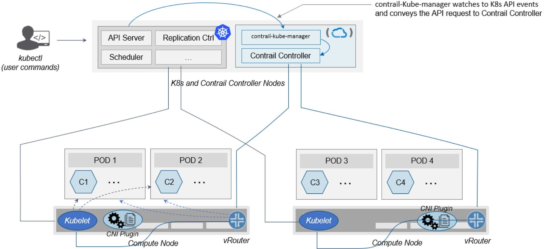
Contrail-Kube-Manager
A new module of Contrail has been added called contrail-kube-manager, abbreviated as KM. It watches
the Kubernetes API server for interested Kubernetes resources, and
translates them into a Contrail controller object. Figure 1 illustrates
the basic workflow.
Kubernetes to Contrail Object Mapping
This is not much of a change from the regular Contrail that
we know and love, but there’s a lot happening behind the scenes.
Be aware that dealing with Kubernetes/Contrail is all about object
mapping. That’s because Contrail is a single interface managing
multiple environments, and each environment has its own acronyms and
terms and hence the need for this mapping, which is done by a plugin.
In Kubernetes, contrail-kube-manager does
this.
Juniper Contrail has specific plugins for each environment/orchestrator. To learn more and get up-to-date release information, go to Juniper Contrail at https://www.juniper.net/us/en/products-services/sdn/contrail/.
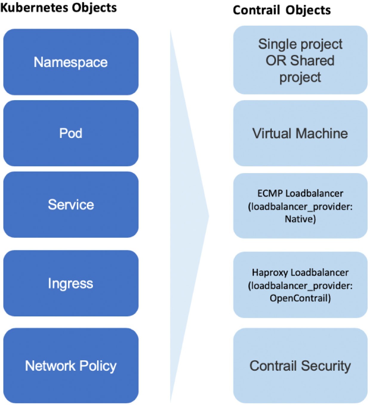
For example, namespaces in Kubernetes are intended for segmentation between multiple teams, or projects, as if creating virtual clusters. In Contrail the similar concept is named project so when you create a namespace in Kubernetes it will automatically create an equivalent project in Contrail. More on that will come later, but for now familiarizing yourself with the list of objects shown in Figure 2 will help you understand the architecture.
Contrail Namespaces and Isolation
In Chapter 3 you read about namespace or NS in Kubernetes, and at the beginning of this chapter we mentioned
object mappings between Kubernetes and Contrail. In this section you’ll
see how namespace works in Contrail environments and how Contrail
extends the feature set even further.
One analogy given when introducing the namespace concept is OpenStack project, or tenant. And that is exactly how Contrail is looking
at it. Whenever a new namespace object
is created, contrail-kube-manager (KM)
gets a notice about the object creation event and it will create the
corresponding project in Contrail.
To differentiate between multiple Kubernetes clusters in Contrail,
a Kubernetes cluster name will be added to the Kubernetes namespace
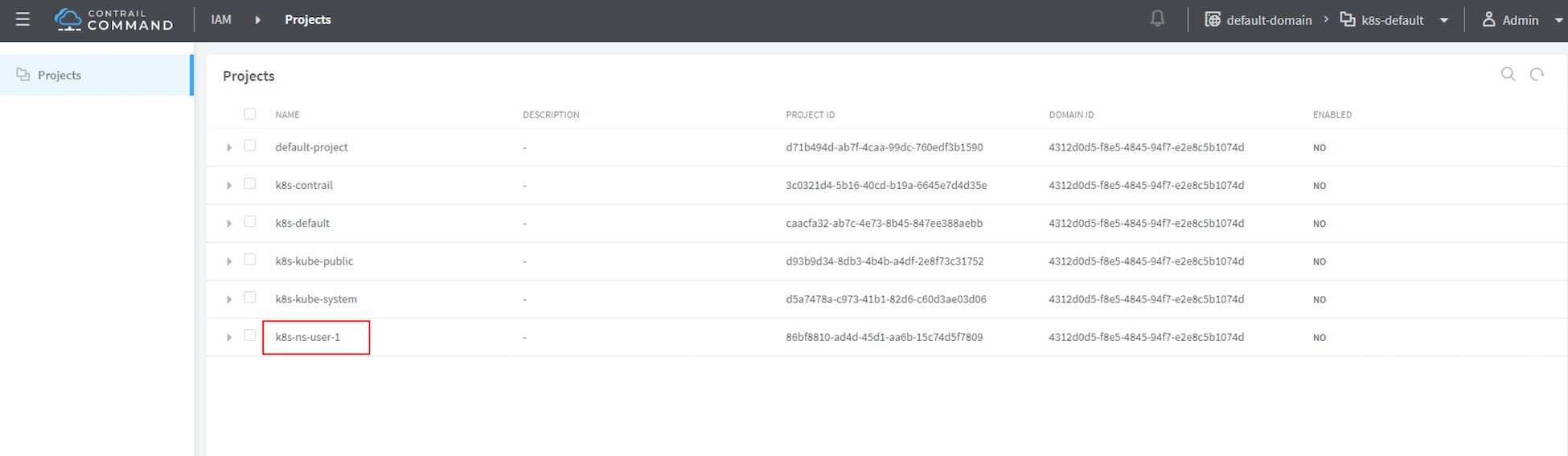
or project name. The default Kubernetes cluster name is k8s. So if you create a Kubernetes namespace ns-user-1, a k8s-ns-user-1 project will be created in Contrail just as you can see here in Figure 3, which shows
the Contrail GUI.
The Kubernetes cluster name is configurable,
but only during the deployment process. If you don’t configure
it k8s will be the default. Once the cluster
is created, the name cannot be changed. To view the cluster
name, you have to go to the contrail-kube-manager (KM) docker and check its configuration file.
To locate the KM docker container:
$ docker ps -a | grep kubemanager
2260c7845964 ...snipped... ago Up 2 minutes kubemanager_kubemanager_1
To log in to the KM container:
$ docker exec -it kubemanager_kubemanager_1 bash
To find the cluster_name option:
$ grep cluster /etc/contrail/contrail-kubernetes.conf
cluster_name=k8s	#<---
cluster_project={}
cluster_network={}
The rest of this book will refer to all these terms namespace, NS, tenant, and project interchangeably.
Non-Isolated Namespaces
You should be aware that one Kubernetes basic networking requirement is for a flat/NAT-less network – any pod can talk to any pod in any namespace – and any CNI provider must ensure that. Consequently, in Kubernetes, by default, all namespaces are not isolated:
The term isolated and non-isolated are in the context of (Contrail) networking only.
k8s-default-pod-network and k8s-default-service-network
To provide networking for all non-isolated namespaces, there should be a common VRF (virtual routing and forwarding) table or routing instance. In the Contrail Kubernetes environment, two default virtual networks are pre-configured in k8s’ default namespace, for pod and for service, respectively. Correspondingly, there are two VRF tables, each with the same name as their corresponding virtual network.
The name of the two virtual networks/VRF tables is in this format:
<k8s-cluster-name>-<namespace name>-[pod|service]-network
So, for the default namespace with a default cluster name, k8s, the two Virtual network/VRF table names are:
k8s-default-pod-network: the pod virtual network/VRF table, with the default subnet10.32.0.0/12k8s-default-service-network: the service virtual network /VRF table, with a default subnet10.96.0.0/12
The default subnet for pod or service is configurable.
It is important to know that these two default virtual networks are shared between all of the non-isolated namespaces. What that means is that they will be available for any new non-isolated namespace that you create, implicitly. That’s why pods from all non-isolated namespaces, including default namespaces, can talk to each other.
On the other hand, any virtual networks that you create will be isolated with other virtual networks, regardless of the same or different namespaces. Communication between pods in two different virtual networks requires Contrail network policy.
Later, when you read about Kubernetes service , you may wonder why packets destined for the service virtual network/VRF table can reach the backend pod in pod virtual network/VRF table. Again, the good news is because of Contrail network policy. By default, Contrail network policy is enabled between the service and pod networks, which allows packets arriving to the service virtual network/VRF table to reach the pod, and vice versa.
Isolated Namespaces
In contrast, isolated namespaces have their own default pod-network
and service-network, and accordingly, two new VRF tables are also
created for each isolated namespace. The same flat-subnets 10.32.0.0/12 and 10.96.0.0/12 are shared by the pod and service networks in the isolated namespaces.
However, since the networks are with a different VRF table, by default
it is isolated with another namespace. Pods launched in isolated namespaces
can only talk to service and pods on the same namespace. Additional
configurations, for example, policy, are required to make the pod
able to reach the network outside of the current namespace.
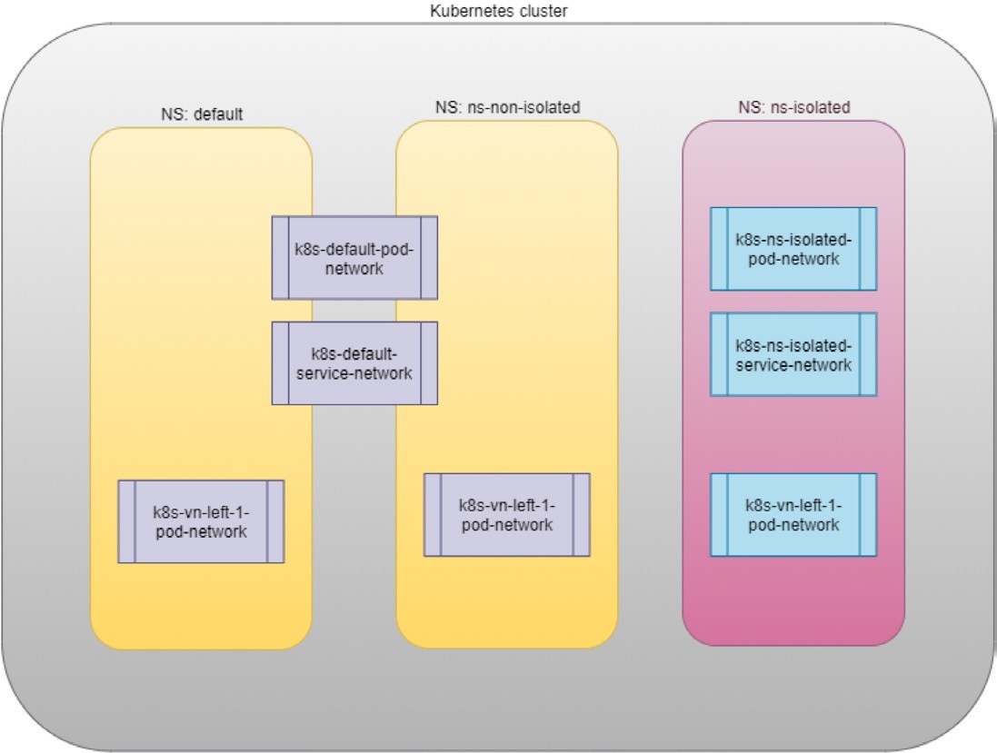
To illustrate this concept, let’s use an example. Suppose
you have three namespaces: the default namespace,
and two user namespaces: ns-non-isolated and ns-isolated. In each namespace you
can create one user virtual network: vn-left-1. You will end up following virtual network/VRF tables in Contrail:
default-domain:k8s-default:k8s-default-pod-network
default-domain:k8s-default:k8s-default-service-network
default-domain:k8s-default:k8s-vn-left-1-pod-network
default-domain:k8s-ns-non-isolated:k8s-vn-left-1-pod-network
default-domain:k8s-ns-isolated:k8s-ns-isolated-pod-network
default-domain:k8s-ns-isolated:k8s-ns-isolated-service-network
default-domain:k8s-ns-isolated:k8s-vn-left-1-pod-network
The above names are listed in FQDN format. In Contrail, domain is the top-level object, followed by project/tenant, and then followed by virtual networks.
Figure 4 expertly illustrates all this.
Here is the YAML file to create an isolated namespace:
$ cat ns-isolated.yaml
apiVersion: v1
kind: Namespace
metadata:
annotations:
"opencontrail.org/isolation" : "true"
name: ns-isolated
And to create the NS:
kubectl create -f ns-isolated.yaml

$ kubectl get ns
NAME	STATUS AGE
contrail	Active 8d
default	Active 8d
ns-isolated Active 1d #<---
kube-public Active 8d kube-
system Active 8d
The annotations under metadata are an additional way to compare standard (non-isolated) k8s namespace. The value of true indicates this is an isolated namespace:
annotations:
"opencontrail.org/isolation" : "true"
You can see that this part of the definition is Juniper’s
extension. The contrail-kube-manager (KM) reads the namespace metadata from kube-apiserver,
parses the information defined in the annotations object, and sees that the isolation flag
is set to true. It then creates the tenant with the corresponding
routing instance (one for pod and one for service) instead of using
the default namespace routing instances for the isolated namespace.
Fundamentally that is how the isolation is implemented.
The following sections will verify that the routing isolation is working.
Pods Communication Across NS
Create a non-isolated namespace and an isolated namespace:
$ cat ns-non-isolated.yaml
apiVersion: v1
kind: Namespace
metadata:
name: ns-non-isolated

$ cat ns-isolated.yaml
apiVersion: v1
kind: Namespace
metadata:
annotations:
"opencontrail.org/isolation": "true"
name: ns-isolated

$ kubectl apply -f ns-non-isolated.yaml
namespace/ns-non-isolated created

$ kubectl apply -f ns-isolated.yaml
namespace/ns-isolated created

$ kubectl get ns | grep isolate
ns-isolated	 Active 79s
ns-non-isolated Active 73s
In both namespaces and the default namespace, create a deployment to launch a webserver pod:
#deploy-webserver-do.yaml
apiVersion: apps/v1
- {key: app, operator: In, values: [webserver]}

$ kubectl apply -f deploy-webserver-do.yaml -n default
deployment.extensions/webserver created

$ kubectl apply -f deploy-webserver-do.yaml -n ns-non-isolated
deployment.extensions/webserver created
$ kubectl apply -f deploy-webserver-do.yaml -n ns-isolated
deployment.extensions/webserver created

$ kubectl get pod -o wide -n default
NAME	READY  STATUS   ... IP	NODE ...
webserver-85fc7dd848-tjfn6 1/1 Running ... 10.47.255.242 cent333 ...
$ kubectl get pod -o wide -n ns-non-isolated...
NAME	READY  STATUS   ... IP	NODE ...
webserver-85fc7dd848-nrxq6 1/1 Running ... 10.47.255.248 cent222 ...

$ kubectl get pod -o wide -n ns-isolated
NAME	READY  STATUS   ... IP	NODE ...
webserver-85fc7dd848-6l7j2 1/1 Running ... 10.47.255.239 cent222 ...
Ping between all pods in three namespaces:
#default ns to non-isolated new ns: succeed
$ kubectl -n default exec -it webserver-85fc7dd848-tjfn6 -- ping 10.47.255.248
PING 10.47.255.248 (10.47.255.248): 56 data bytes
64 bytes from 10.47.255.248: seq=0 ttl=63 time=1.600 ms
^C
--- 10.47.255.248 ping statistics ---
1 packets transmitted, 1 packets received, 0% packet loss
round-trip min/avg/max = 1.600/1.600/1.600 ms

#default ns to isolated new ns: fail
$ kubectl -n default exec -it webserver-85fc7dd848-tjfn6 -- ping 10.47.255.239
PING 10.47.255.239 (10.47.255.239): 56 data bytes
^C
--- 10.47.255.239 ping statistics ---
3 packets transmitted, 0 packets received, 100% packet loss
The test result shows that bidirectional communication between
two non-isolated namespaces (namespace ns-non-isolated and default, in this case) works, but
traffic from a non-isolated namespace (default ns) toward an isolated namespace does not pass through. What about
traffic within the same isolated namespace?
With the power of deployment you
can quickly test it out: in isolated namespace ns-isolated, clone one more pod by scale the deployment with replicas=2 and ping between the two pods:
$ kubectl scale deployment webserver --replicas=2
$ kubectl get pod -o wide -n ns-isolated
NAME	READY  STATUS    RESTARTS AGE IP	NODE
webserver-85fc7dd848-6l7j2  1/1   Running 0	8s 10.47.255.239 cent222
webserver-85fc7dd848-215k8  1/1   Running 0		8s 10.47.255.238 cent333

$ kubectl -n ns-isolated exec -it webserver-85fc7dd848-6l7j2 -- ping 10.47.255.238
PING 10.47.255.238 (10.47.255.238): 56 data bytes
64 bytes from 10.47.255.238: seq=0 ttl=63 time=1.470 ms


^C
--- 10.47.255.238 ping statistics ---
1 packets transmitted, 1 packets received, 0% packet loss
round-trip min/avg/max = 1.470/1.470/1.470 ms
The ping packet passes through now. To summarize the test results:
Traffic is not isolated between non-isolated namespace.
Traffic is isolated between an isolated namespace and all other tenants in the cluster.
Traffic is not isolated in the same namespace.
Pod-level isolation can be achieved via Kubernetes network policy, or security groups in Contrail, all covered later in this chapter.
Contrail Floating IP
Communication has been discussed and tested between pods in the same or different namespace, but so far, it’s been inside of the same cluster. What about communication with devices outside of the cluster?
You may already know that in the traditional (OpenStack) Contrail environment, there are many ways for the overlay entities (typically a VM) to access the Internet. The three most frequent methods are:
Floating IP
Fabric SNAT
Logical router
The preferred Kubernetes solution is to expose any service via service and Ingress objects,
which you’ve read about in Chapter 3. In the Contrail Kubernetes
environment, floating IP is used in the service and ingress implementation
to expose them to what’s outside of the cluster. Later this
chapter discusses each of these two objects. But first, let’s
review the floating IP basis and look at how it works with Kubernetes.
The fabric SNAT and logical router are used by overlay workloads (VM and
pod) to reach the Internet but initializing communication from the
reverse direction is not possible. However floating IP supports traffic initialized from both directions – you
can configure it to support ingress traffic, egress traffic, or both,
and the default is bi-directional. This book focuses only on floating IP. Refer to Contrail documentation for detailed
information about the fabric SNAT and logical router: https://www.juniper.net/documentation/en_US/contrail5.0/information-products/pathway-pages/contrail-feature-guide-pwp.html.
Floating IP and Floating IP Pool
The floating IP, or FIP for short,
is a traditional concept that Contrail has supported since its very
early releases. Essentially, it’s an OpenStack concept to map
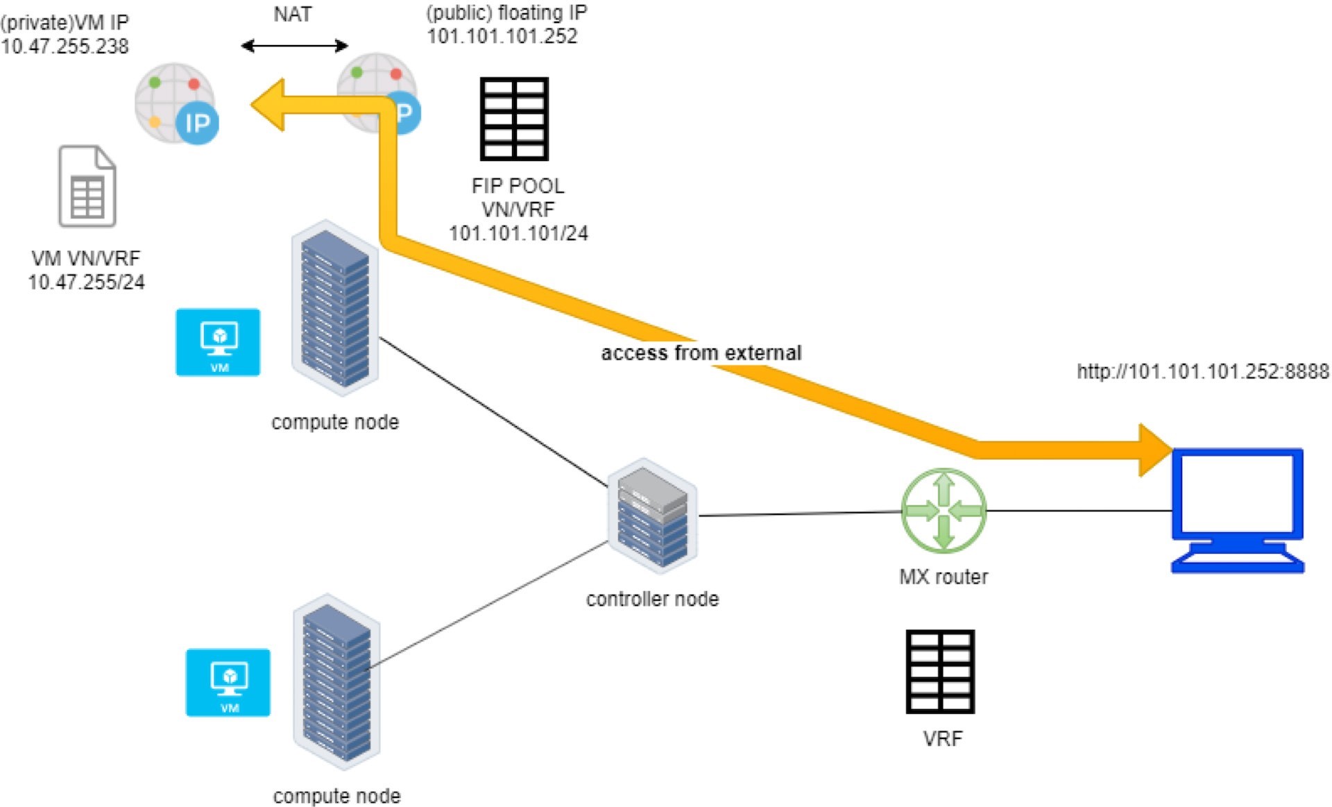
a VM IP, which is typically a private IP address, to a public IP (the
floating IP in this context) that is reachable from the outside of
the cluster. Internally, the one-to-one mapping is implemented by
NAT. Whenever a vRouter receives packets from outside of the cluster
destined to the floating IP, it will translate it to the VM’s
private IP and forward the packet to the VM. Similarly, it will do
the translation on the reverse direction. Eventually both VM and Internet
host can talk to each other, and both can initiate the communication.
The vRouter is a Contrail forwarding plane that resides in each compute node handling workload traffic.
Figure 5 illustrates the basic workflow of floating IP.
Here are some highlights regarding floating IP to keep in mind:
A floating IP is associated with a VM’s
port, or a VMI (Virtual Machine Interface).A floating IP is allocated from a
FIP pool.A floating IP pool is created based on a virtual network (
FIP-VN).The FIP-VN will be available to outside of the cluster, by setting matching
route-target (RT)attributes of the gateway router’s VRF table.When a gateway router sees a match with its route import policy in the RT, it will load the route into its VRF table. All remote clients connected to the VRF table will be able to communicate with the floating IP.
There is nothing new in the Contrail Kubernetes environment
regarding the floating IP concept and role. But the use of floating
IP has been extended in Kubernetes service and ingress object implementation, and
it plays an important role for accessing Kubernetes service and ingress externally.
You can check later sections in this chapter for more details.
Create FIP Pool
Let’s create a floating IP pool in a three-step process:
Create a public floating IP-VN.
Set RT (route-target) for the virtual network so it can be advertised and imported into the gateway router’s VRF table.
Create a floating IP pool based on the public floating IP-virtual network.
Again, there is nothing new here. The same steps would be required in other Contrail environments without Kubernetes. However, as you’ve learned in previous sections, with Contrail Kubernetes integration a floating IP-virtual network can now be created in Kubernetes style.
Create a Public Floating IP-Virtual Network Named vn-ns-default
# vn-ns-default.yaml
apiVersion: k8s.cni.cncf.io/v1
kind: NetworkAttachmentDefinition
metadata:
annotations:
"opencontrail.org/cidr": "101.101.101.0/24"
name: vn-ns-default
spec:
config: '{
			"cniVersion": "0.3.0",
			"type": "contrail-k8s-cni"
}'

$ kubectl apply -f vn-ns-default.yaml
networkattachmentdefinition.k8s.cni.cncf.io/vn-ns-default created

$ kubectl get network-attachment-definitions.k8s.cni.cncf.io
NAME	AGE
vn-ns-default 22d
Now set the routing target.
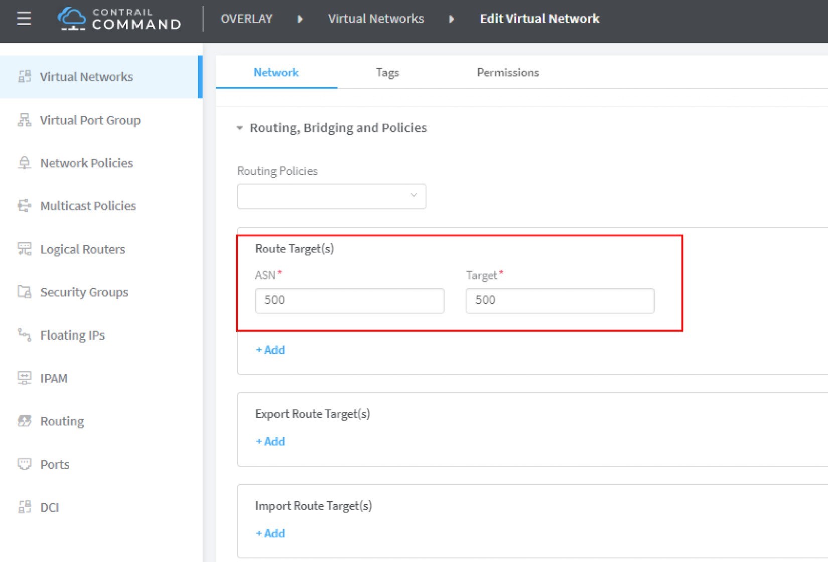
If you need the floating IP to be reachable from the Internet through the gateway router, you’ll need to set a route target for the virtual network prefix getting imported in the gateway router’s VRF table (see Figure 6). This step is necessary whenever Internet access is required.
The UI navigation path to set the RT is: Contrail Command > Main Menu > Overlay > Virtual Networks > k8s-vn-ns-default-pod-network > Edit > Routing, Bridging and Policies.
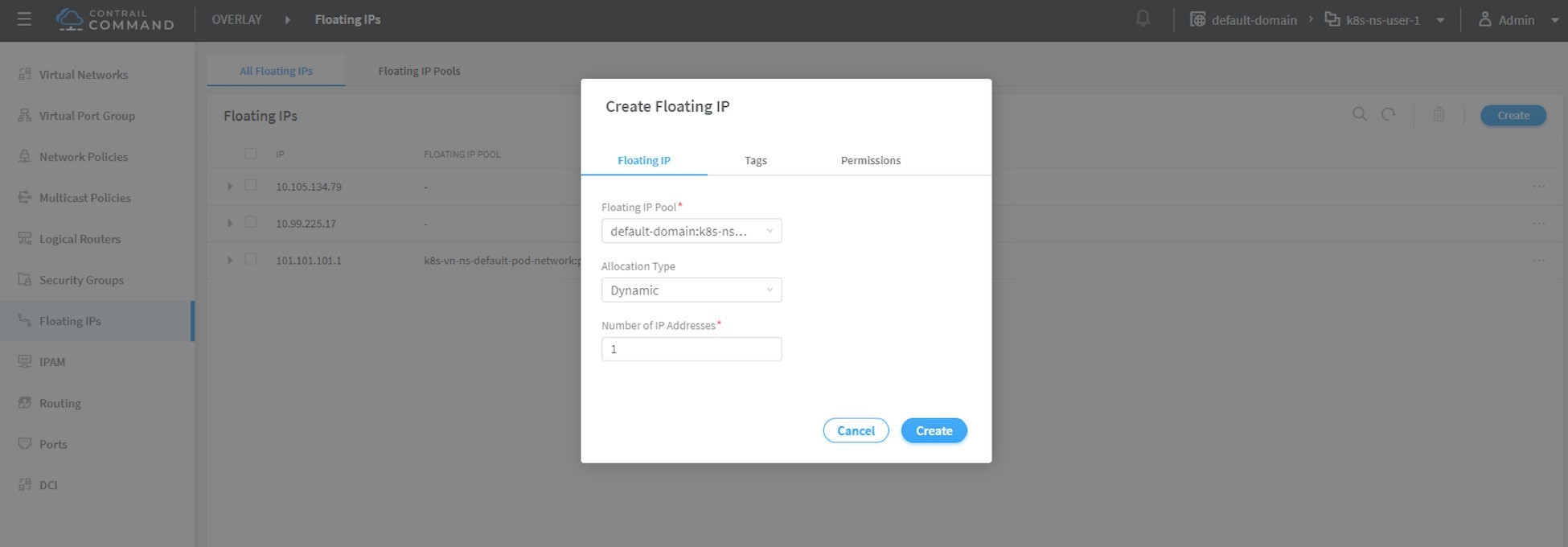
Now let’s create a floating IP pool based on the public virtual network.
This is the final step. From the Contrail Command UI, create a floating IP pool based on the public virtual network. The UI navigation path for this setting shown in Figure 7 is: Contrail Command > Main Menu > Overlay > Floating IP > Create.
The Contrail UI also allows you to set the external flag in virtual network advanced options, so that a floating IP pool named public will automatically be created.
Floating IP Pool Scope
There are different ways you can refer to a floating IP pool in the Contrail Kubernetes environment, and correspondingly the scope of the pools will also be different. The three possible levels with descending priority are:
Object specific
Namespace level
Global level
Object Specific
This is the most specific level of scope. An object specific
floating IP pool binds itself only to the object that you specified,
it does not affect any other objects in the same namespace or cluster.
For example, you can specify a service object web to get floating IP from the floating IP pool pool1, a service object dns to get floating
IP from another floating IP pool pool2,
etc. This gives the most granular control of where the floating IP
will be allocated from for an object – the cost is that you
need to explicitly specify it in your YAML file for every object.
Namespace Level
In a multi-tenancy environment each namespace would be associated
to a tenant, and each tenant would have a dedicated floating IP pool.
In that case, it is better to have an option to define a floating
IP pool at the NS level, so that all objects created in that namespace
will get floating IP assignment from that pool. With the namespace
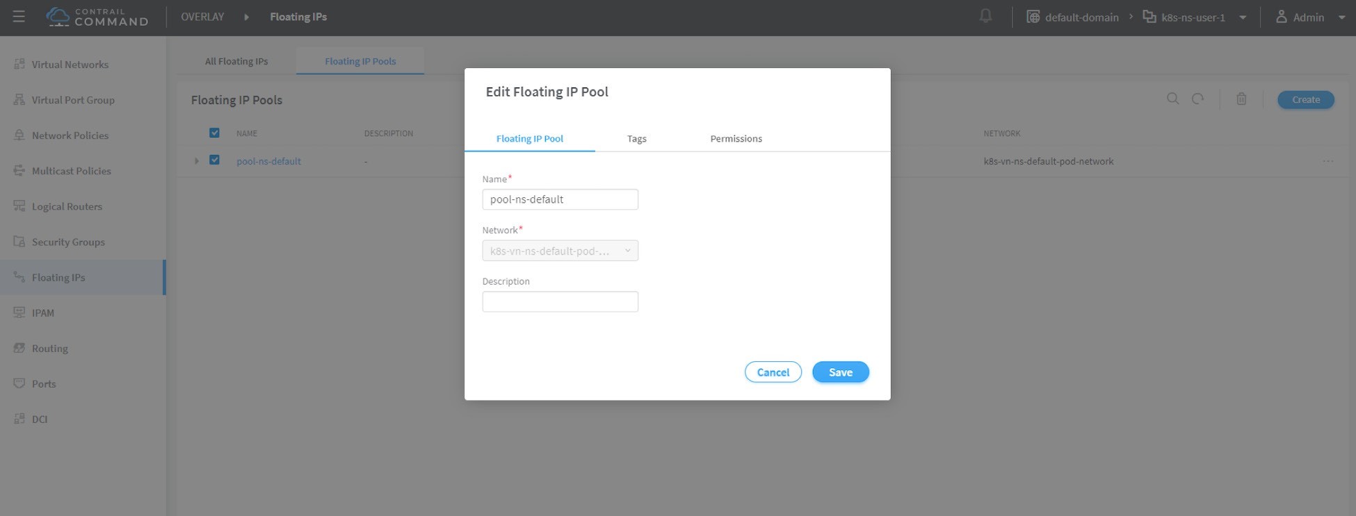
level pool defined (for example, pool-ns-default), there is no need to specify the floating IP-pool name in each
object’s YAML file any more. You can still give a different
pool name, say my-webservice-pool in an
object webservice. In that case, object
webservice will get the floating IP from my-webservice-pool instead of from the namespace level pool pool-ns-default, because the former is more specific.
Global Level
The scope of the global level pool would be the whole cluster. Objects in any namespaces can use the global floating IP pool.
You can combine all three methods to take advantage of their combined flexibility. Here’s a practical example:
Define a global pool
pool-global-default, so any objects in a namespace that has no namespace-level or ob- ject-level pool defined, will get a floating IP from this pool.For ns
dev, define a floating IP poolpool-dev, so all objects created in nsdevwill by default get floating IP frompool-dev.For ns
sales, define a floating IP poolpool-sales, so all objects created in nssaleswill by default get floating IP frompool-sales.For ns
test-only, do not define any namespace-level pool, so by default objects created in it will get floating IP from thepool-global-default.When a service
dev-webservicein ns dev needs a floating IP frompool-salesinstead ofpool-dev, specifyingpool-salesindev-webserviceobject YAML file will achieve this goal.
Just keep in mind the rule of thumb – the most specific scope will always prevail.
Object Floating IP Pool
Let’s first take a look at the object-specific floating IP pool:
#service-web-lb-pool-public-1.yaml
apiVersion: v1
kind: Service
metadata:
name: service-web-lb-pool-public-1
annotations:
"opencontrail.org/fip-pool": "{'domain': 'default-domain', 'project': 'k8s-ns-user-1', 'network': 'vn-public-1', 'name': 'pool-public-1'}"
spec:
ports:
- port: 8888
targetPort: 80
selector:
app: webserver
type: LoadBalancer
In this example, service service-web-lb-pool-public-1 will get an floating IP from pool pool-public-1, which is created based on virtual network vn-public-1 under current project k8s-ns-user-1.
The corresponding Kubernetes namespace is ns-user-1. Since object-level floating IP pool is assigned for this specific
object only, with this method each new object needs to be explicitly
assigned a floating IP pool.
NS Floating IP Pool
The next floating IP pool scope is in the namespace level. Each namespace can define its own floating IP pool. In the same way as a Kubernetes annotations object is used to give a subnet to a virtual network, it is also used to specify a floating IP pool. The YAML file looks like this:
#ns-user-1-default-pool.yaml
apiVersion: v1
kind: Namespace
metadata:
annotations:
opencontrail.org/isolation: "true"
opencontrail.org/fip-pool: "{'domain': 'default-domain', 'project': 'k8s-ns-user-1', 'network': 'vn-ns-default', 'name': 'pool-ns-default'}"
name: ns-user-1
Here ns-user-1 is given a namespace-level
floating IP pool named pool-ns-default,
and the corresponding virtual network is vn-ns-default. Once the ns-user-1 is created with this
YAML file, any new service which requires a floating IP, if not created
with the object-specific pool name in its YAML file, will get a floating
IP allocated from this pool. In practice, most namespaces (especially
those isolated namespaces) will need their own namespace default pool
so you will see this type of configuration very often in the field.
Global floating IP Pool
To specify a global level floating IP pool, you need to give
the fully-qualified pool name (domain > project > net-
work > name) in contrail-kube-manager (KM) Docker’s configuration file(/etc/contrail/contrail-kubernetes.conf). This file is automatically generated by the Docker during its
bootup based on its ENV parameters, which can be found in the /etc/contrail/common_kubemanager.env file in the master
node:
$ cat /etc/contrail/common_kubemanager.env
VROUTER_GATEWAY=10.169.25.1
CONTROLLER_NODES=10.85.188.19
KUBERNETES_API_NODES=10.85.188.19
RABBITMQ_NODE_PORT=5673
CLOUD_ORCHESTRATOR=kubernetes
KUBEMANAGER_NODES=10.85.188.19
CONTRAIL_VERSION=master-latest
KUBERNETES_API_SERVER=10.85.188.19
TTY=True
ANALYTICS_SNMP_ENABLE=True
STDIN_OPEN=True
ANALYTICS_ALARM_ENABLE=True
ANALYTICSDB_ENABLE=True
CONTROL_NODES=10.169.25.19
As you can see, this .env file contains
important environmental parameters about the setup. To specify a global FIP pool, add the following line:
KUBERNETES_PUBLIC_FIP_POOL={'domain': 'default-domain','name':
'pool-global-default','network': 'vn-global-default','project': 'k8s-ns-user-1'}
It reads: the global floating IP pool is called pool-global-default and it is defined based on a virtual
network vn-global-default under project k8s-ns-user-1. This indicates that the corresponding
Kubernetes namespace is ns-user-1.
Now with that piece of configuration placed, you can re-compose
the contrail-kube-manager Docker container
to make the change take effect. Essentially you need to tear it down
and then bring it back up:
$ cd /etc/contrail/kubemanager/
$ docker-compose down;docker-compose up -d
Stopping kubemanager_kubemanager_1 ... done
Removing kubemanager_kubemanager_1 ... done
Removing kubemanager_node-init_1 ... done
Creating kubemanager_node-init_1 ... done
Creating kubemanager_kubemanager_1 ... done
Now the global floating IP pool is specified for the cluster.
In all three scopes, floating IP is automatically allocated and associated only to service and ingress objects. If the floating IP has to be associated to a pod it has to be done manually. We’ll talk about this in the next section.
Floating IP for Pods
Once floating IP pool is created and available, a floating IP can be allocated from the floating IP pool for the pods that require one. This can be done by associating a floating IP to a VMI (VM, or pod, interface), You can manually create a floating IP out of a floating IP pool in Contrail UI, and then associate it with a pod VMI as in Figure 8 and Figure 9
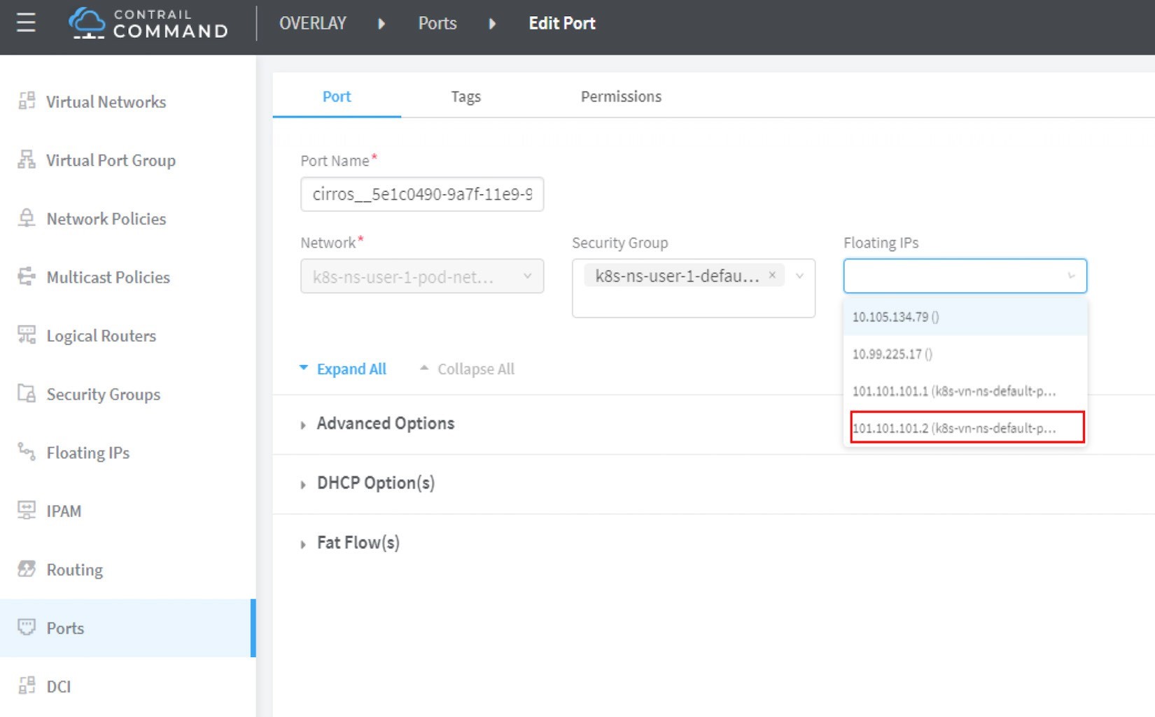
Make sure the floating IP pool is shared to the project where floating IP is going to be created.
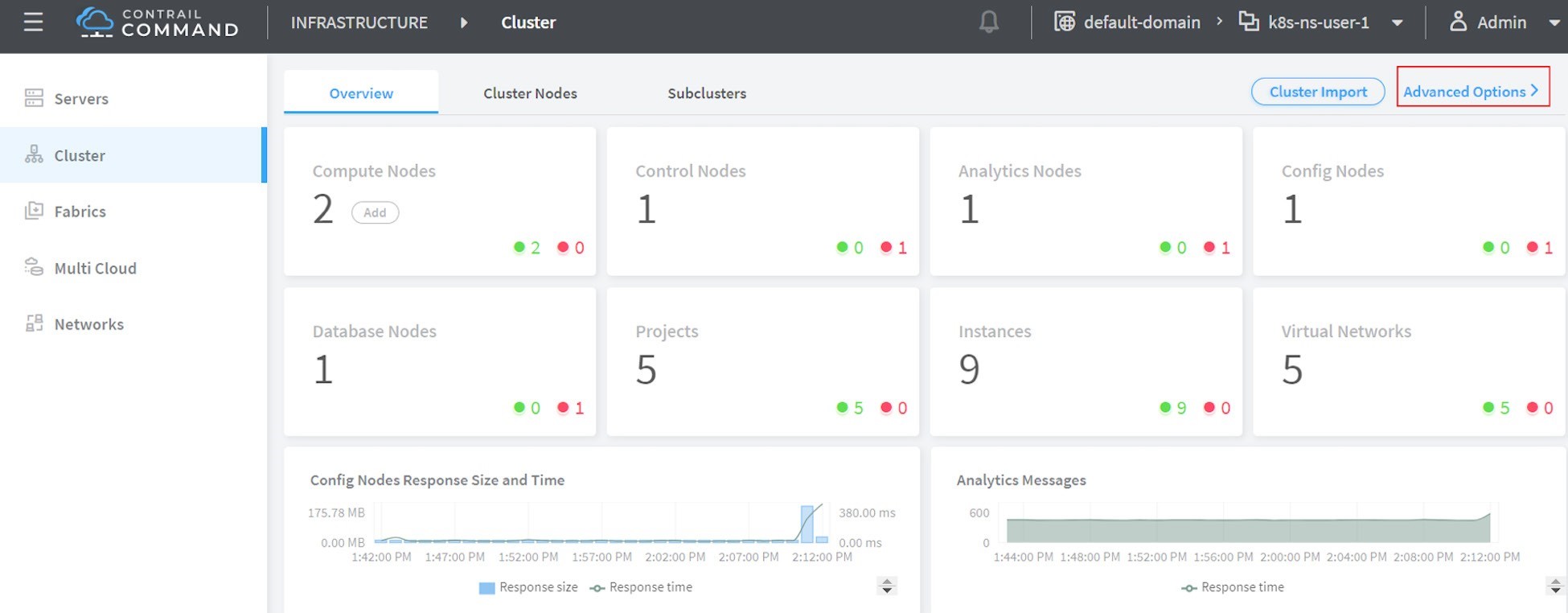
Advertising Floating IP
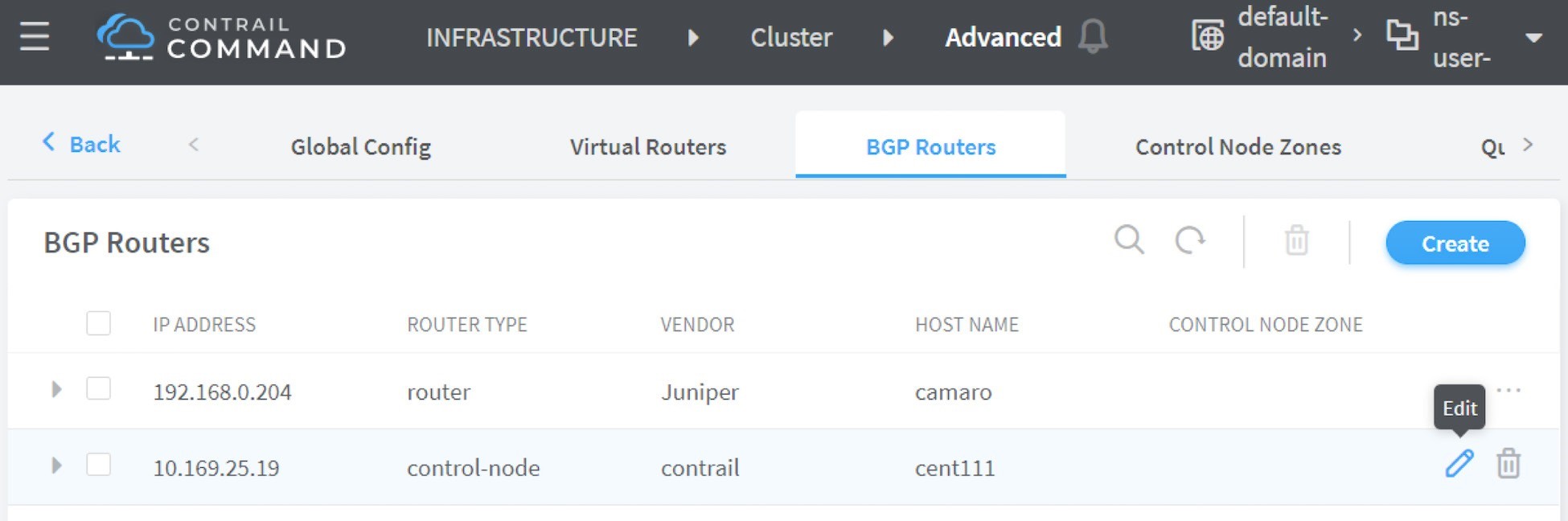
Once a floating IP is associated to a pod interface, it will be advertised to the MP-BGP peers, which are typically gateway routers. The following Figures, Figure 10, Figure 11, and Figure 12, show how to add and edit a BGP peer.
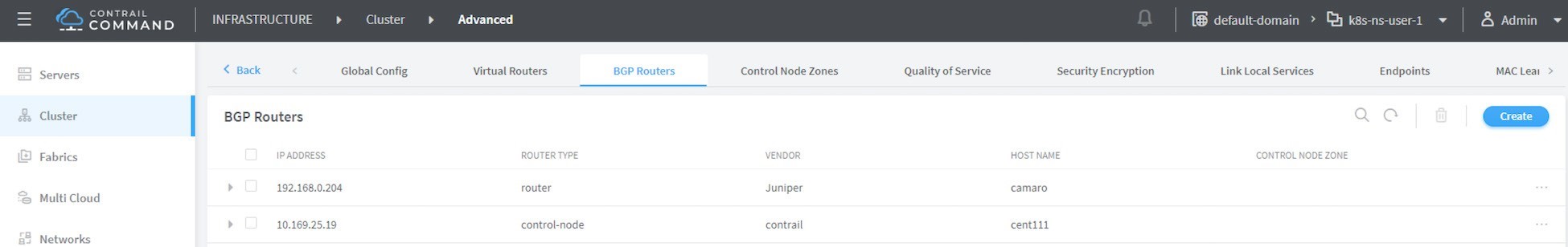
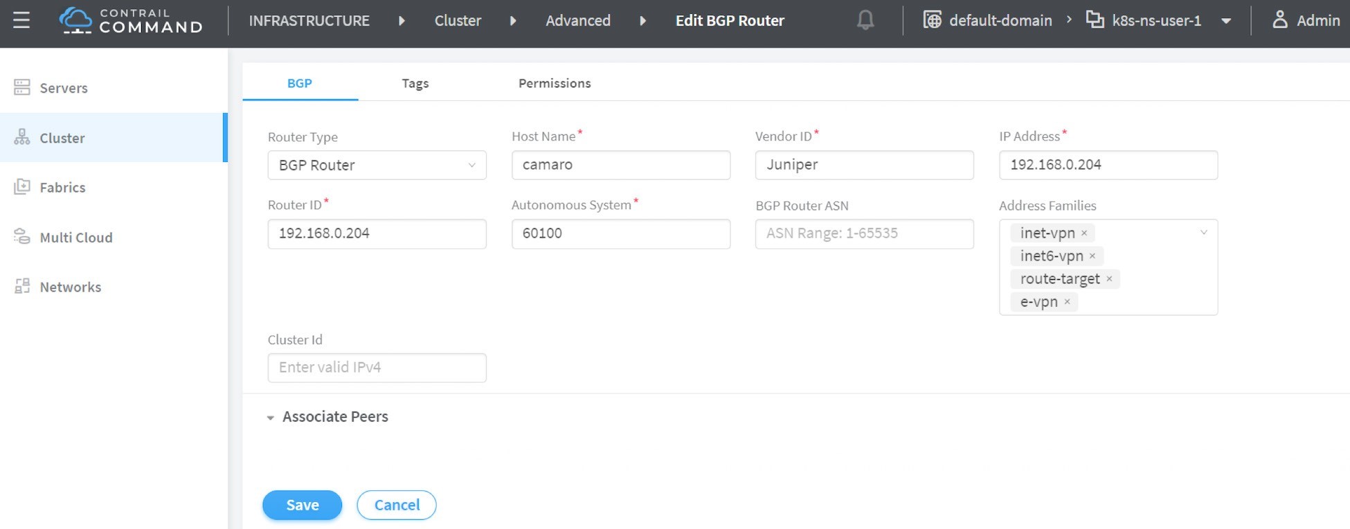
Input all the BGP peer information and don’t forget to associate the controller(s), which is shown next in Figure 13.
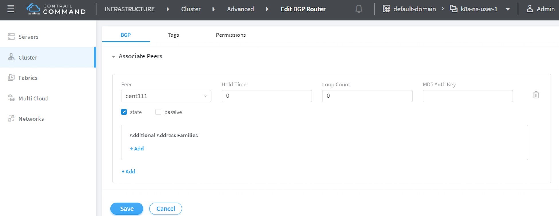
From the dropdown of peer under Associated Peers, select the controller(s) to peer
with this new BGP router that you are trying to add. Click save when done. A new BGP peer with ROUTER TYPE router
will pop up.
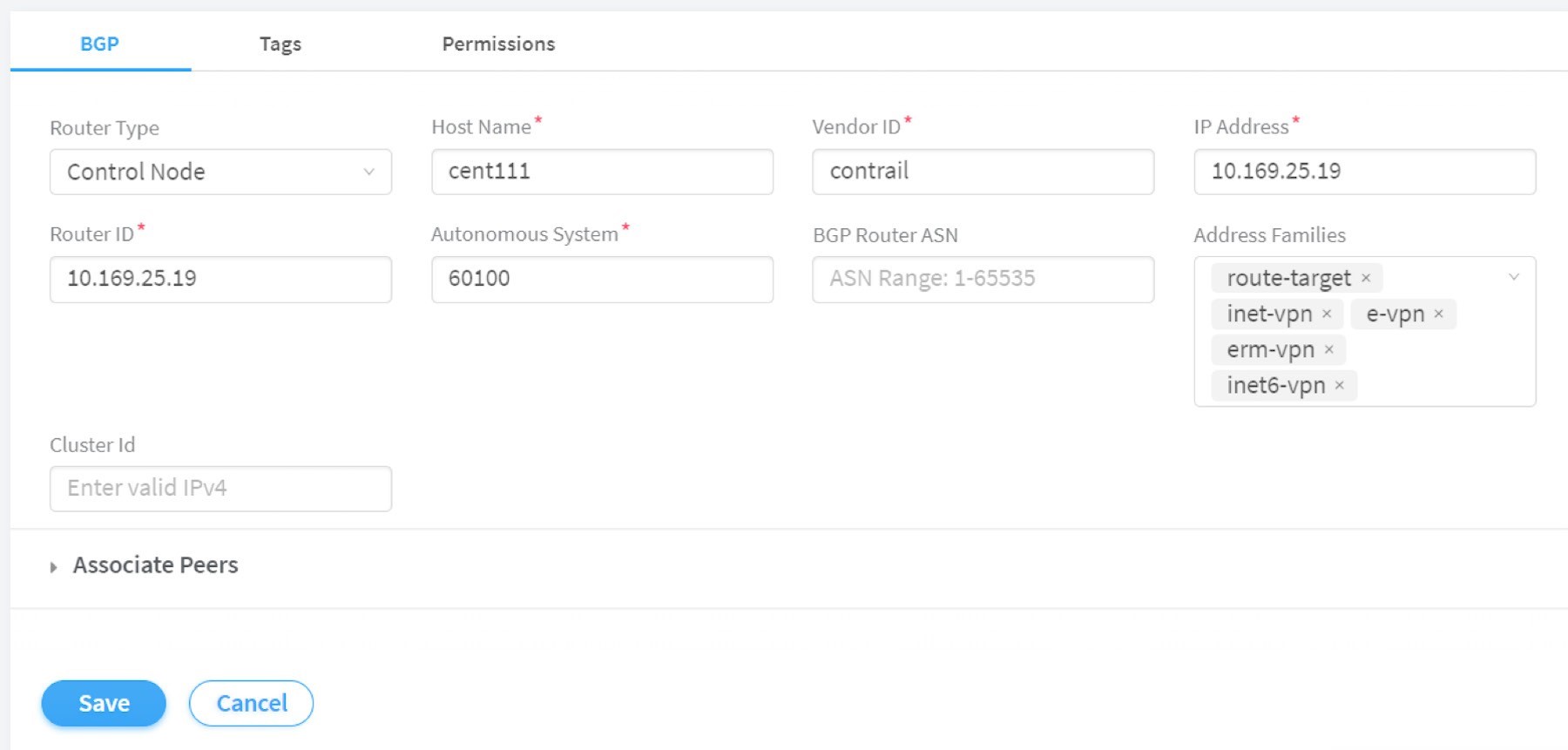
Now we’ve added a peer BGP router as type router. For the local BGP speaker, which is with type control-node, you just need to double-check the parameters by clicking the Edit button. In this test we want to build an MP-IBGP neighborship between Contrail Controller and the gateway router, so make sure the ASN and Address Families fields match on both ends, refer to Figure 15.
Now you can check BGP neighborship status in the gateway router:
labroot@camaro> show bgp summary | match 10.169.25.19
10.169.25.19	60100	2235	2390	0	39 18:19:34 Establ
Once the neighborship is established, BGP routes will be exchanged between the two speakers, and that is when we’ll see that the floating IP assigned to the Kubernetes object is advertised by the master node (10.169.25.19) and learned in the gateway router:
labroot@camaro> show route table k8s-test.inet.0 101.101.101.2
Jul 11 01:18:31

k8s-test.inet.0: 8 destinations, 8 routes (8 active, 0 holddown, 0 hidden)
@ = Routing Use Only, # = Forwarding Use Only
+ = Active Route, - = Last Active, * = Both

101.101.101.2/32 *[BGP/170] 00:01:42, MED 200, localpref 100, from 10.169.25.19
AS path: ?
validation-state: unverified, > via gr-2/3/0.32771, Push 47
The detail version of the same command
tells more: the floating IP route is reflected from the Contrail Con-
troller, but Protocol next hop being the
compute node (10.169.25.20) indicates that
the floating IP is assigned to a compute node. One entity currently
running in that compute node owns the floating IP:
labroot@camaro> show route table k8s-test.inet.0 101.101.101.2 detail | match "next hop"
Jul 11 01:19:18
Next hop type: Indirect, Next hop index: 0
Next hop type: Router, Next hop index: 1453
Next hop: via gr-2/3/0.32771, selected Protocol
next hop: 10.169.25.20
Indirect next hop: 0x900e640 1048601 INH Session ID: 0x70f
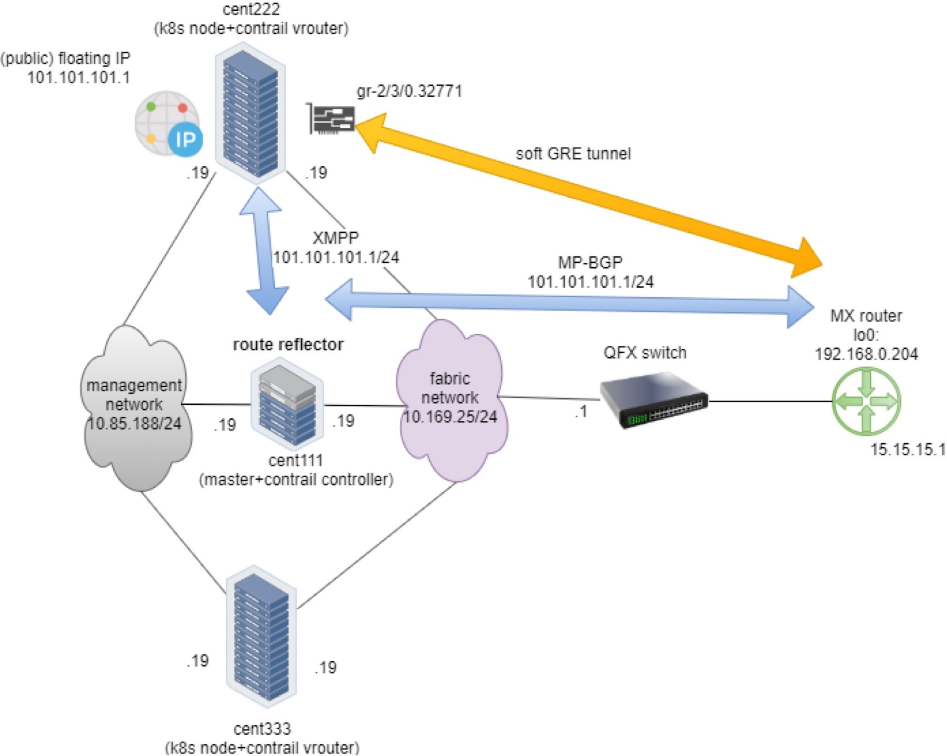
The dynamic soft GRE configuration makes the gateway router automatically create a soft GRE tunnel interface:
labroot@camaro> show interfaces gr-2/3/0.32771
Jul 11 01:19:53
Logical interface gr-2/3/0.32771 (Index 432) (SNMP ifIndex 1703)
Flags: Up Point-To-Point SNMP-Traps 0x4000
IP-Header 10.169.25.20:192.168.0.204:47:df:64:0000000800000000 Encapsulation: GRE-NULL
Copy-tos-to-outer-ip-header: Off, Copy-tos-to-outer-ip-header-transit: Off
Gre keepalives configured: Off, Gre keepalives adjacency state: down
Input packets : 0
Output packets: 0
Protocol inet, MTU: 9142
Max nh cache: 0, New hold nh limit: 0, Curr nh cnt: 0, Curr new hold cnt: 0, NH drop cnt: 0
Flags: None
Protocol mpls, MTU: 9130, Maximum labels: 3
Flags: None
The IP-Header indicates a GRE outer
IP header, so the tunnel is built from the current gateway router
whose BGP local address is 192.168.0.204, to the remote node 10.169.25.20, in
this case it’s one of the Contrail compute nodes. The floating
IP advertisement process is illustrated in Figure 16.
Summary
In this chapter we created the following objects:
Ns: ns-user-1
FIP VN: vn-ns-default
FIP pool: pool-ns-default
The ns-user-1 ns project, which refers
to a namespace-level pool pool-ns-default that is to be created manually, will hold all of our test objects.
The namespace-level pool is based on the virtual network vn-ns-default that has subnet 101.101.101/24. The floating
IP for objects created in namespace ns-user-1 will be assigned from
this subnet.
Once you have YAML files (given earlier) ready for the namespace and floating IP-virtual network, you can create these objects:
The floating IP-pool needs to be created separately in Contrail’s UI. Refer to the Contrail Floating IP section for the details.
With these objects there is a namespace associated with a floating IP pool. From inside of this namespace you can proceed to create and study other Kubernetes objects, such as Service.
All tests in this book that demonstrate service and ingress will be created under this ns-user-1 namespace.