Contrail Service Chaining with CSRX
Service chaining is the concept of forwarding traffic through multiple network entities in a certain order, and each network entity performs specific functions, such as firewall, IPS, NAT, LB, etc. The legacy way of doing service chaining would be to use standalone HW appliances, but this makes service chaining inflexible, expensive, and lengthens set up times. In dynamic service chaining network functions are deployed as a VM or a container and can be chained automatically in a logical way. For example, Figure 1 uses Contrail for service chaining between two pods in two different networks using a cSRX container Level 4 – Level 7 firewall to secure the traffic between them.
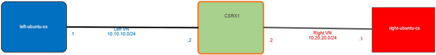
Left and right networks are used here just for simplicity’s sake, to follow the flow from left to right, but you can use your own names of course. Make sure to configure the network before you attach a pod to it or else the pod will not be created.
Bringing Up Client and CSRX Pods
Let’s create two virtual networks using this YAML file:
Verify using Kubectl:
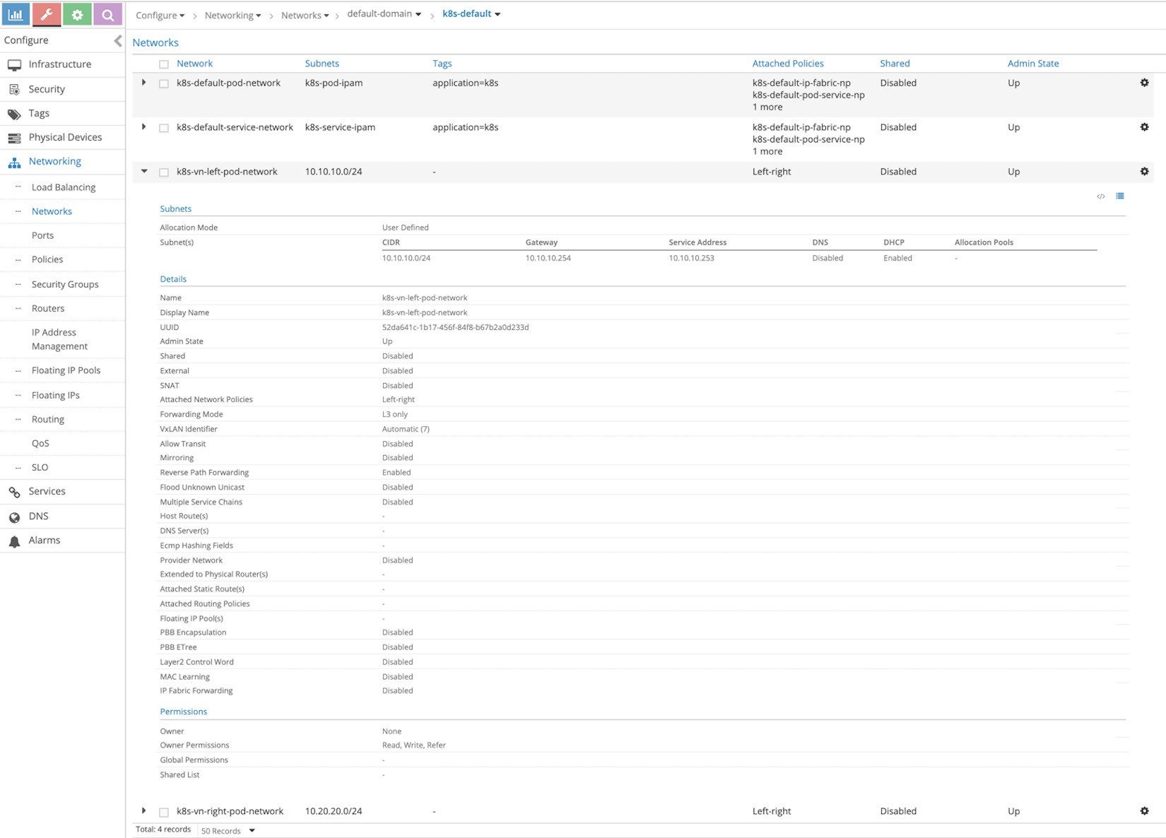
It’s good practice to confirm that these two networks are now in Contrail before proceeding. From the Contrail UI, select Configure > Networking > Networks > default-domain > k8s-default is shown in Figure 2, which focuses on the left network.
If you use the default namespace in the YAML file for a network, it will create it in the domain default-domain and project k8s-default.
Create Client Pods
Now let’s create two Ubuntu Pods, one in each network using the following annotation object:
#left-ubuntu-sc.yaml
apiVersion: v1
kind: Pod
metadata:
name: left-ubuntu-sc
labels:
app: webapp-sc
annotations:
k8s.v1.cni.cncf.io/networks: '[
{ "name": "vn-left" }]'
spec:
containers:
		- name: ubuntu-left-pod-sc
		image: contrailk8sdayone/ubuntu securityContext:
		privileged: true
		capabilities:
		add:
			- NET_ADMIN


#right-ubuntu-sc.yaml
apiVersion: v1
kind: Pod
metadata:
name: right-ubuntu-sc
labels:
app: webapp-sc
annotations:
k8s.v1.cni.cncf.io/networks: '[
{ "name": "vn-right" }]'
spec:
containers:
		- name: ubuntu-right-pod-sc
		image: contrailk8sdayone/ubuntu
		securityContext:
		privileged: true
		capabilities:
		add:
			- NET_ADMIN

# kubectl create -f
right-ubuntu-sc.yaml #
kubectl create -f left-
ubuntu-sc.yaml


# kubectl get pod
NAME	READY STATUS RESTARTS AGE
left-ubuntu-sc    1/1
 Running   0
					25h
right-ubuntu-sc   1/1
Running   0
					25h

# kubectl describe pod
Name:	left-ubuntu-sc
Namespace:	default
Priority:	0
PriorityClassName: <none>
Node:	cent22/10.85.188.17
Start Time:		Thu, 13 Jun 2019 03:40:20 -0400
Labels:	app=webapp-sc
Annotations:
				k8s.v1.cni.cncf.io/
				network-status: [
			{
				"ips": "10.10.10.1",


			"mac": "02:7d:b1:09:00:8d",
			"name": "vn-left"
		},
	{
			"ips": "10.47.255.249",
			"mac": "02:7d:99:ff:62:8d",
		"name": "cluster-wide-default"
		}
	]
	k8s.v1.cni.cncf.io/networks: [
{ "name": "vn-left" }]
Status:	Running
IP:	10.47.255.249
Containers:
ubuntu-left-pod-sc:
Container ID:
docker://2f9a22568d844c68a1c4a45de4a81478958233052e
08d4473742827482b244cd
Image:	contrailk8sdayone/ubuntu
Image ID:	docker-pullable://contrailk8sdayone/ubuntu@sha256:fa2930cb8f4b766e5b335dfa42de510ecd30af6433ceada14cdaae8de9065d2a

...<snipped>...

Name:	right-ubuntu-sc
Namespace:	default
Priority:	0
PriorityClassName: <none>
Node:	cent22/10.85.188.17
Start Time:		Thu, 13 Jun 2019 04:09:18 -0400
Labels:	app=webapp-sc
Annotations:
			k8s.v1.cni.cncf.io/
			network-status: [
				{
					"ips": "10.20.20.1",
					"mac": "02:89:cc:86:48:8d",
					"name": "vn-right"
				},
			{
			"ips": "10.47.255.252",
			"mac": "02:89:b0:8e:98:8d",
			"name": "cluster-wide-default"
		}
	]
	k8s.v1.cni.cncf.io/networks: [
{ "name": "vn-right" }]
Status:	Running
IP:	10.47.255.252
Containers:
ubuntu-right-pod-sc:
Container ID: docker://4e0b6fa085905be984517a11c3774517d01f481fa
43aadd76a633ef15c58cbfe
Image:	contrailk8sdayone/ubuntu
Image ID:	docker-pullable://contrailk8sdayone/ubuntu@sha256:fa2930cb8f4b766e5b335dfa42de510ecd30af6433ceada14cdaae8de9065d2a

...<snipped>...
Create cSRX Pod
Now create a Juniper cSRX container that has one interface on the left network and one interface on the right network, using this YAML file:
Confirm that the interface placement is in the correct network:
# kubectl describe
pod csrx1-sc
Name:	csrx1-sc
Namespace:	default
Priority:	0
PriorityClassName: <none>
Node:	cent22/10.85.188.17
Start Time:		Thu, 13 Jun 2019 03:40:31 -0400
Labels:	app=webapp-sc
Annotations:
			k8s.v1.cni.cncf.io/
			network-status: [
				{
					"ips": "10.10.10.2",
					"mac": "02:84:71:f4:f2:8d",
					"name": "vn-left"
				},
			{
					"ips": "10.20.20.2",
					"mac": "02:84:8b:4c:18:8d",
					"name": "vn-right"
				},
			{
					"ips": "10.47.255.248",
					"mac": "02:84:59:7e:54:8d",
					"name": "cluster-wide-default"
			}
		]
		k8s.v1.cni.cncf.io/networks: [ { "name":
 "vn-left" }, { "name": "vn-right" } ]
Status:	Running
IP:	10.47.255.248
Containers: csrx1-sc:


Container ID: docker://82b7605172d937895269d76850d083b6dc6e278e41cb45b4cb8cee21283e4f17
Image:	contrailk8sdayone/csrx
Image ID:	docker://sha256:329e805012bdf081f4a15322f994e5e3116b31c90f108a19123cf52710c7617e

...<snipped>...
Each container has one interface belonging to cluster-wide-default network regardless of the use of the annotations object because the annotations object above creates, and puts one extra interface in, a specific network.
Verify PodIP
To verify the podIP, log in to the left pord, right Pod and the cSRX to confirm the IP/MAC addresses:
# kubectl exec -it
left-ubuntu-sc bash
root@left-ubuntu-sc:/# ip a
1: lo: <LOOPBACK,UP,LOWER_UP> mtu 65536 qdisc
		noqueue state UNKNOWN group default qlen 1000
		link/loopback 00:00:00:00:00:00 brd 00:00:00:00:00:00
		inet 127.0.0.1/8 scope host lo
		valid_lft forever preferred_lft forever
13: eth0@if14: <BROADCAST,MULTICAST,UP,LOWER_UP>
		mtu 1500 qdisc noqueue state UP group default link/ether
 		02:7d:99:ff:62:8d brd ff:ff:ff:ff:ff:ff
		inet 10.47.255.249/12
		scope global eth0
		valid_lft forever
		preferred_lft forever
15: eth1@if16: <BROADCAST,MULTICAST,UP,LOWER_UP>
		mtu 1500 qdisc noqueue state UP group default link/ether
		02:7d:b1:09:00:8d brd ff:ff:ff:ff:ff:ff
		inet 10.10.10.1/24
		scope global eth1
		valid_lft forever
		preferred_lft forever


# kubectl exec -it
right-ubuntu-sc bash
root@right-ubuntu-sc:/# ip a
1: lo: <LOOPBACK,UP,LOWER_UP> mtu 65536 qdisc
		noqueue state UNKNOWN group default qlen 1000
		link/loopback 00:00:00:00:00:00 brd 00:00:00:00:00:00
		inet 127.0.0.1/8 scope host lo
		valid_lft forever preferred_lft forever
23: eth0@if24: <BROADCAST,MULTICAST,UP,LOWER_UP>
		mtu 1500 qdisc noqueue state UP group default link/ether
		02:89:b0:8e:98:8d brd ff:ff:ff:ff:ff:ff
		inet 10.47.255.252/12
		scope global eth0
		valid_lft forever
		preferred_lft forever
25: eth1@if26: <BROADCAST,MULTICAST,UP,LOWER_UP>
		mtu 1500 qdisc noqueue state UP group default link/ether
		02:89:cc:86:48:8d brd ff:ff:ff:ff:ff:ff
		inet 10.20.20.1/24
		scope global eth1
		valid_lft forever
		preferred_lft forever


# kubectl exec -
it csrx1-sc cli
root@csrx1-sc>
root@csrx1-sc> show interfaces
Physical interface: ge-0/0/1,
Enabled, Physical link is Up
Interface index: 100
Link-level type: Ethernet, MTU: 1514
Current address: 02:84:71:f4:f2:8d, Hardware address: 02:84:71:f4:f2:8d

Physical interface: ge-0/0/0,
Enabled, Physical link is Up
Interface index: 200
Link-level type: Ethernet, MTU: 1514
Current address: 02:84:8b:4c:18:8d, Hardware address: 02:84:8b:4c:18:8d
Unlike other pods the cSRX didn’t acquire IP with DHCP, and it starts with the factory default configuration hence it needs to be configured.
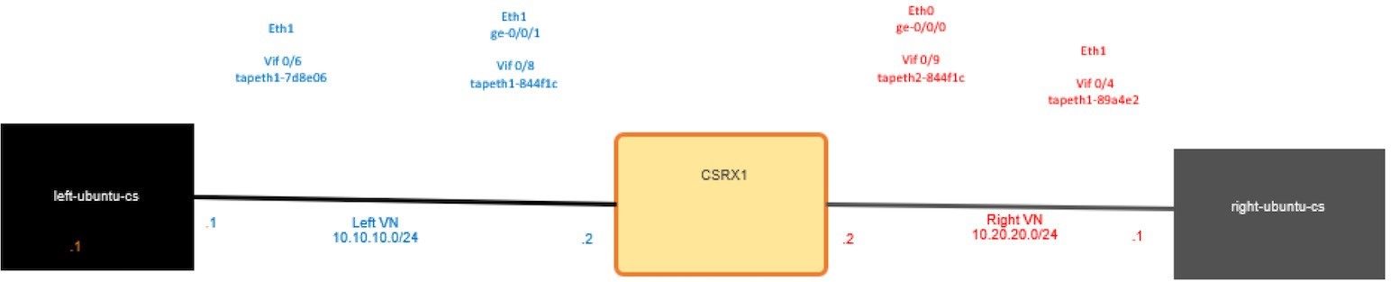
By default, cSRX eth0 is visible only from the shell and used for management. When attaching networks, the first attached network is mapped to eth1, which is GE-0/0/1, and the second attached is mapped to eth2, which is GE-0/0/0.
Configure cSRX IP
Configure this basic setup on the cSRX. To assign the correct IP address, use the MAC/IP address mapping from the kubectl describe pod command output as well as to configure the default security policy to allow everything for now:
set interfaces ge-0/0/1 unit 0 family
inet address 10.10.10.2/24 set
interfaces ge-0/0/0 unit 0 family inet
address 10.20.20.2/24
set security zones security-zone
trust interfaces ge-0/0/0 set
security zones security-zone
untrust interfaces ge-0/0/1 set
security policies default-policy
permit-all commit
Verify the IP address assigned on the cSRX:
root@csrx1-sc> show interfaces
Physical interface: ge-0/0/1,
Enabled, Physical link is Up
Interface index: 100
Link-level type: Ethernet, MTU: 1514
Current address: 02:84:71:f4:f2:8d, Hardware address: 02:84:71:f4:f2:8d
Logical interface ge-
0/0/1.0 (Index 100)
Flags: Encapsulation:
ENET2 Protocol inet
Destination: 10.10.10.0/24, Local: 10.10.10.2
Physical interface: ge-0/0/0,
Enabled, Physical link is Up
Interface index: 200
Link-level type: Ethernet, MTU: 1514
Current address: 02:84:8b:4c:18:8d, Hardware address: 02:84:8b:4c:18:8d
Logical interface ge-
0/0/0.0 (Index 200)
Flags: Encapsulation:
 ENET2 Protocol inet
Destination: 10.20.20.0/24, Local: 10.20.20.2
A ping test on the left pod would fail as there is no route:
Add a static route to the left and right pods and then try to ping again:
The ping still failed, as we didn’t create the service chaining, which will also take care of the routing. Let’s see what happened to our packets:
There’s no session on the cSRX. To troubleshoot the ping issue, log in to the compute node cent22 that hosts this container to dump the traffic using TShark and check the routing. To get the interface linking the containers:
[root@cent22
~]# vif -l
Vrouter
Interface Table

Flags: P=Policy, X=Cross Connect, S=Service
		Chain, Mr=Receive Mirror Mt=Transmit
		Mirror, Tc=Transmit Checksum Offload,
		L3=Layer 3, L2=Layer 2 D=DHCP, Vp=Vhost
		Physical, Pr=Promiscuous, Vnt=Native Vlan
		Tagged
		Mnp=No MAC Proxy, Dpdk=DPDK PMD Interface, Rfl=Receive
		Filtering Offload, Mon=Interface is Monitored Uuf=Unknown
		Unicast Flood, Vof=VLAN insert/strip offload, Df=Drop New
		Flows, L=MAC Learning Enabled Proxy=MAC Requests Proxied
		Always, Er=Etree Root, Mn=Mirror without Vlan Tag, Ig=Igmp
		Trap Enabled

...<snipped>...

vif0/3			OS: tapeth0-89a4e2
		Type:Virtual
		HWaddr:00:00:5e:00:01:00
		IPaddr:10.47.255.252 Vrf:3 Mcast
		Vrf:3 Flags:PL3DEr QOS:-1 Ref:6
		RX 		packets:10760
		bytes:452800 		errors:0
		TX packets:14239
		bytes:598366 		errors:0
		Drops:10744

vif0/4			OS: tapeth1-89a4e2
		Type:Virtual
		HWaddr:00:00:5e:00:01:00
		IPaddr:10.20.20.1 Vrf:5 Mcast
		Vrf:5 Flags:PL3DEr QOS:-1 Ref:6
		RX 		packets:13002
		bytes:867603 		errors:0
		TX packets:16435
		bytes:1046981 		errors:0
		Drops:10805

vif0/5			OS: tapeth0-7d8e06
 		Type:Virtual
		HWaddr:00:00:5e:00:01:00
		IPaddr:10.47.255.249 Vrf:3 Mcast
		Vrf:3 Flags:PL3DEr QOS:-1 Ref:6
		RX 		packets:10933
		bytes:459186 		errors:0
		TX packets:		14536
		bytes:610512	 errors:0
		Drops:10933

vif0/6			OS: tapeth1-7d8e06
		Type:Virtual
		HWaddr:00:00:5e:00:01:00
		IPaddr:10.10.10.1 Vrf:6 Mcast
		Vrf:6 Flags:PL3DEr QOS:-1 Ref:6
		RX 		packets:12625
 		bytes:1102433 		errors:0
		TX packets:15651
		bytes:810689 		errors:0
		Drops:10957

vif0/7			OS: tapeth0-844f1c
		Type:Virtual
		HWaddr:00:00:5e:00:01:00
		IPaddr:10.47.255.248 Vrf:3 Mcast
		Vrf:3 Flags:PL3DEr QOS:-1 Ref:6
		RX 		packets:20996
		bytes:1230688 		errors:0
		TX packets:27205
		bytes:1142610 		errors:0
		Drops:21226

vif0/8			OS: tapeth1-844f1c
		Type:Virtual
		HWaddr:00:00:5e:00:01:00
		IPaddr:10.10.10.2 Vrf:6 Mcast
		Vrf:6 Flags:PL3DEr QOS:-1 Ref:6
		RX 		packets:13908
		bytes:742243 		errors:0
		TX packets:29023
		bytes:1790589 		errors:0
		Drops:10514

vif0/9			OS: tapeth2-844f1c
		Type:Virtual
 		HWaddr:00:00:5e:00:01:00
		IPaddr:10.20.20.2 Vrf:5 Mcast
		Vrf:5 Flags:PL3DEr QOS:-1 Ref:6
		RX 		packets:16590
		bytes:1053659 		errors:0
		TX packets:31321
		bytes:1635153 		errors:0
		Drops:10421

...<snipped>...
Note that vif0/3 and vif0/4 are bound with the right pod and both linked to tapeth0-89a4e2 and tapeth1-89a4e2 respectively. The same goes for the left pod for Vif0/5 and vif0/6 while vif0/7, vif 0/8, and vif0/9 are bound with the cSRX1. From this you can also see the number of the packet/bytes that hit the interface, as well as the VRF. VRF 3 is for the default-cluster-network, while VRF 6 is for the left network and VRF 5 is for the right network. In Figure 10.3 you can see the interface mapping from all the perspectives (container, Linux , vr-agent).
Let’s try to ping from the left pod to the right pod again, and use TShark on the tap interface for the right pod for further inspection:
Looks like the ping isn’t reaching the right pod at all, let’s check the cSRX’s left network tap interface:
We can see the packet but there is nothing in the cSRX security prospective to drop this packet
Check the routing table of the left network VRF by logging to the vrouter_vrouter-agent_1 container in the compute node:
[root@cent22 ~]# docker ps | grep vrouter
9a737df53abe	ci-repo.englab.juniper.net:5000/contrail-vrouter-agent:master-latest
"/entrypoint.sh /usr…" 2 weeks ago	Up 47 hou
rs	vrouter_vrouter-agent_1
e25f1467403d	ci-repo.englab.juniper.net:5000/contrail-nodemgr:master-latest
"/entrypoint.sh /bin…" 2 weeks ago	Up 47 hou
rs	vrouter_nodemgr_1

[root@cent22 ~]# docker exec -it
vrouter_vrouter-agent_1 bash
(vrouter-agent)[root@cent22 /]$
(vrouter-agent)[root@cent22 /]$ rt
--dump 6 | grep 10.20.20. (vrouter-
agent)[root@cent22 /]$
Note that 6 is the routing table VRF of the left network; the same would go for the right network VRF routing table but there is a missing route:
So, even if all the pods are hosted on the same compute nodes, they can’t reach each other. And if these pods are hosted on some different compute nodes then you have a bigger problem to solve. Service chaining isn’t just about adjusting the routes on the containers but also about exchanging routes between the vRouter-agent between the compute nodes regardless of the location of the pod (as well as adjusting that automatically if the pod moved to another compute node). Before labbing service-chaining let’s address an important concern for network administrators who are not fans of this kind of CLI troubleshooting… you can do the same troubleshooting using the Contrail Controller GUI.
From the Contrail Controller UI, select Monitor > Infrastructure > Virtual Routers and then select the node that hosts the pod, in our case cent22.local, as shown in the next screen capture, Figure 4.
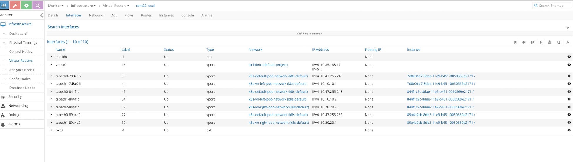
Figure 4 shows the Interface tab, which is equivalent to running the vif -l command on the vrouter_vrouter-agent-1 container, but it shows even more information. Notice the mapping between the instance ID and the tap interface naming, where the first six characters of the instance ID are always reflected in the tap interface naming.
We are GUI cowboys. Let’s check the routing tables of each VRF by moving to the Routes tab and selecting the VRF you want to see, as in Figure 5.
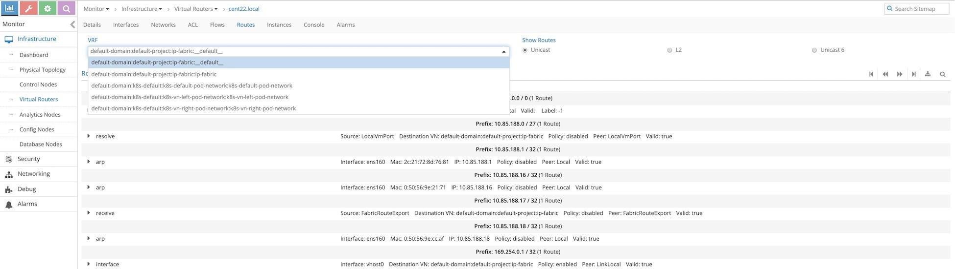
Select the left network. The name is longer because it includes the domain (and project). You can confirm there is no 10.20.20.0/24 prefix from the right network. You can also check the MAC address learned in the left network by selecting L2, the GUI equivalent to the rt--dump 6 --family bridge command.
Service Chaining
Now let’s utilize the cSRX to service chaining using the Contrail Command GUI. Service chaining consists of four steps that need to be completed in order:
- Create a service template;
- Create a service instance based on the service template just completed;
- Create a network policy and select the service instance you created before;
- Apply this network policy onto the network.
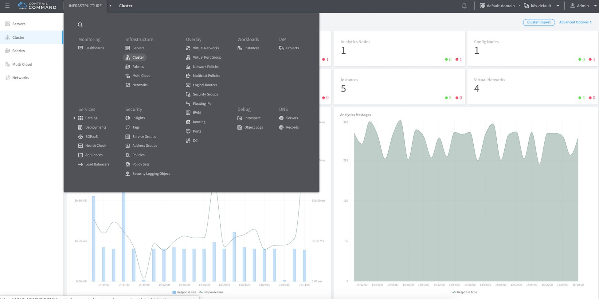
Since Contrail Command GUI is the best solution to provide a single point of management for all environments, we will use it to build service changing. You can still use the normal Contrail controller GUI to build service chaining, too.
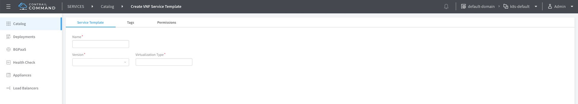
First let’s log in to Contrail Command GUI (in our setup https://10.85.188.16:9091/) as shown next in Figure 7, and then select Service > Catalog > Create as shown in Figure 8.
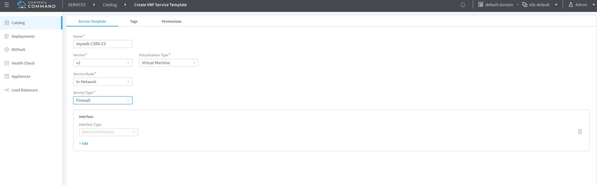
Insert a name of a services template, here myweb-cSRX-CS, then chose v2 and virtual machine for service modes. Choose In-network and Firewall as service types as shown in Figure 9.
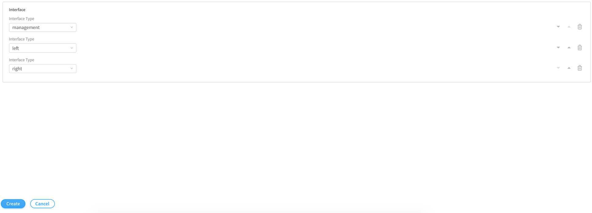
Next select Management, Left and Right, and then click Create.
Now, select Deployment and click on the Create button to create the service instances as shown next in Figure 11.
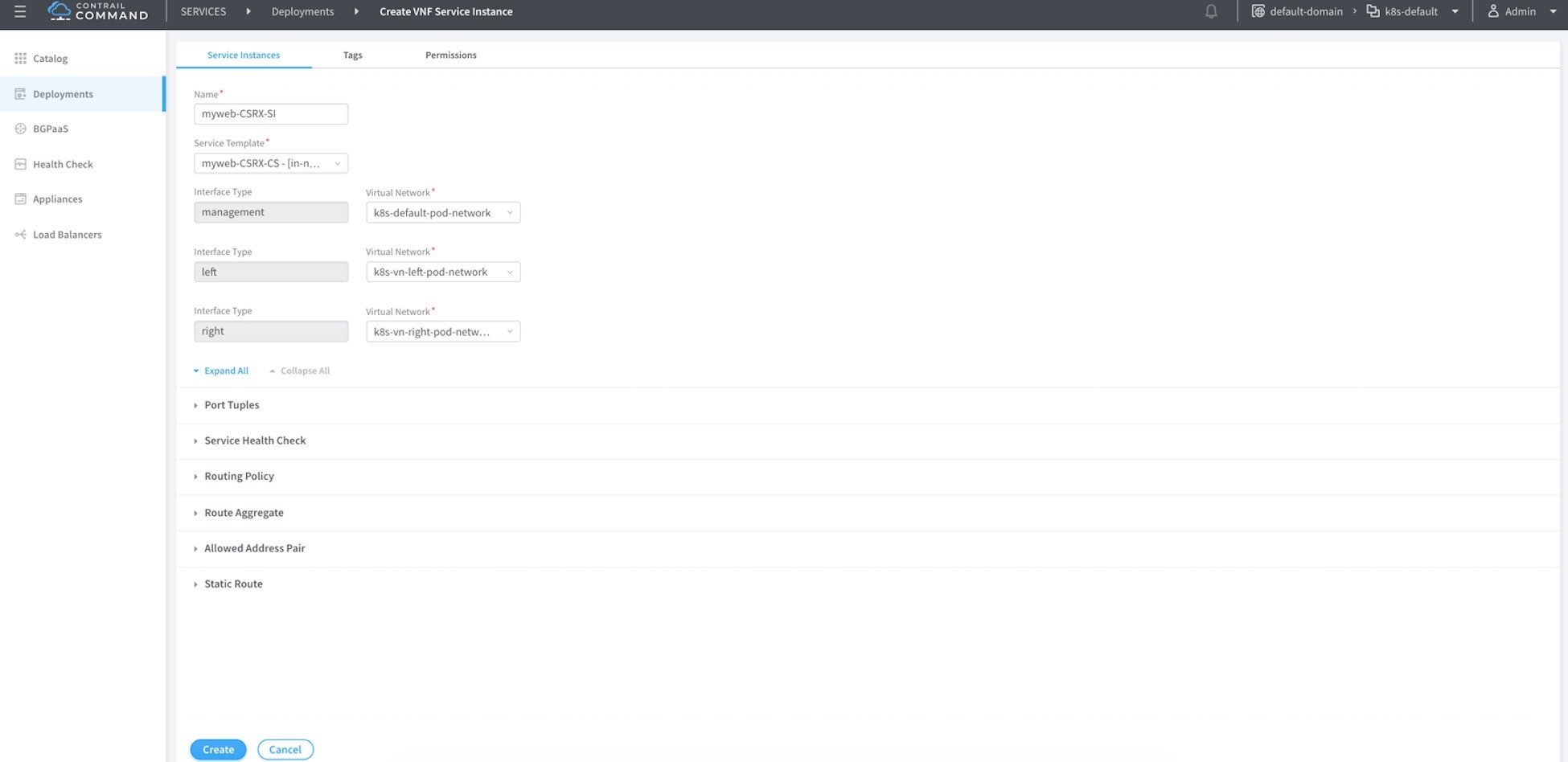
Name this service instance, then select from the drop-down menu the name of the template you created before you chose the proper network from the prospective of the cSRX being the instance (container in that case) that will do the service chaining. Click on the port tuples to expand it as shown in Figure 12. Then, for each of the three interfaces bind one interface of the cSRX, then click Create.
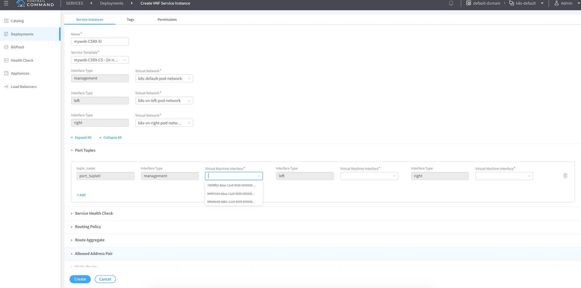
The name of the VM interface isn’t shown in the drop-down menu, instead it’s the instance ID. You can identify that from the tap interface name as we mentioned before. In other words, all you have to know is the first six characters for any interface belonging to that container. All the interfaces in a given instance (VM or container) share the same first characters.
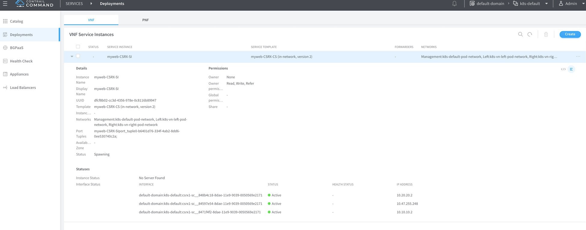
Before proceeding, make sure the statuses of the three interfaces are up and they are showing the correct IP address of the cSRX instance as shown in Figure 13.
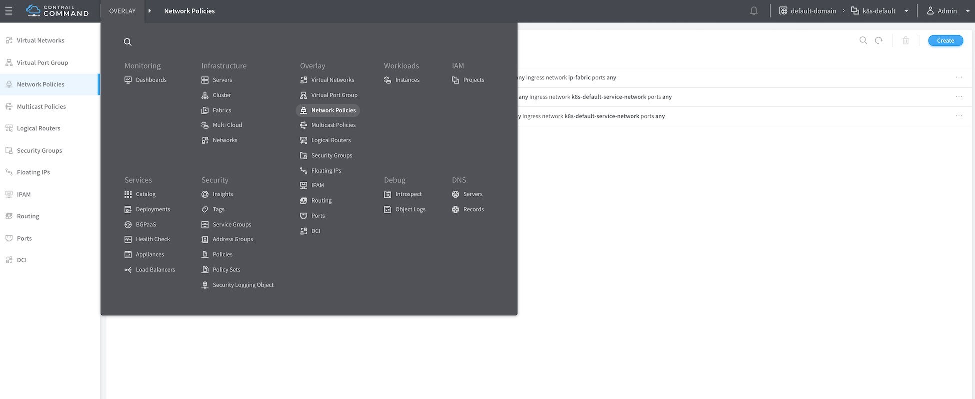
To create the network policy go to Overlay > Network Policies > Create as in Figure 14.
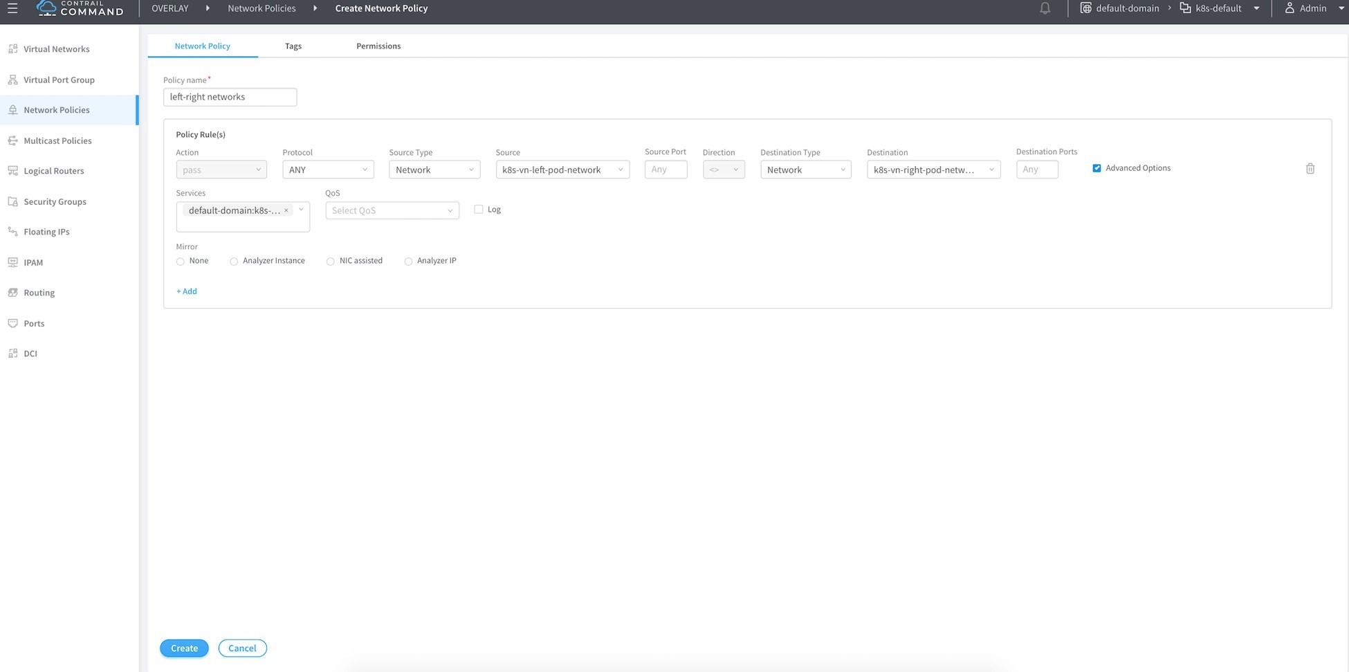
Name your network policy, then in the first rule add left network as the source network and right network as the destination with the action of pass.
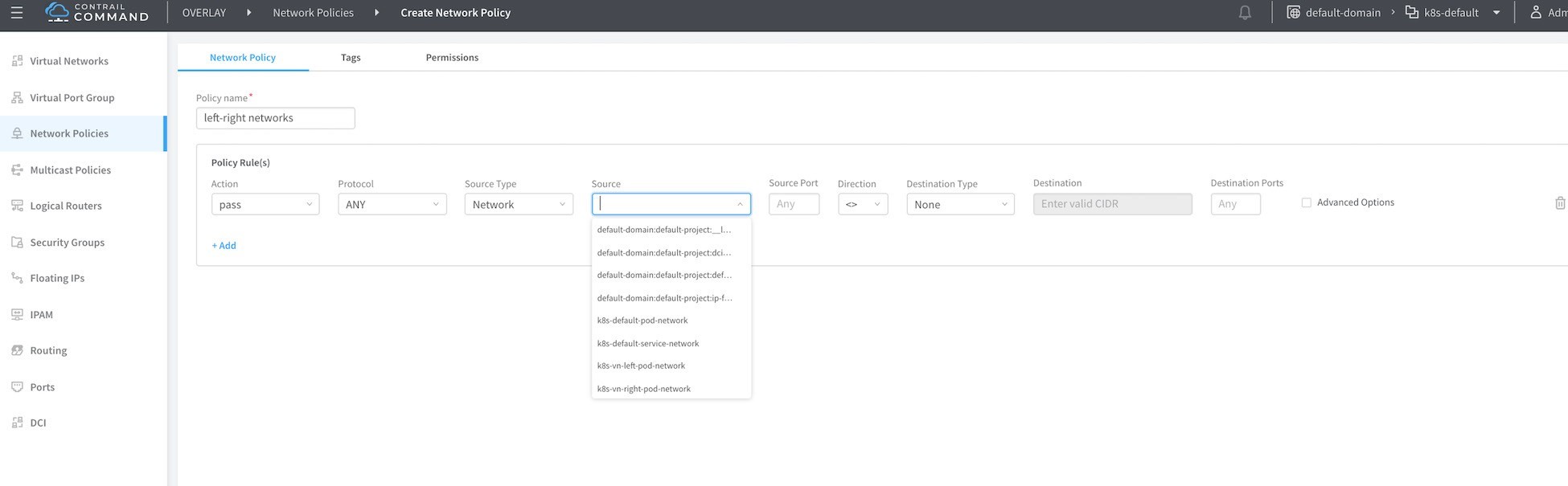
Select the advanced option and attach the service instance to the one you created before, then click the Create button.
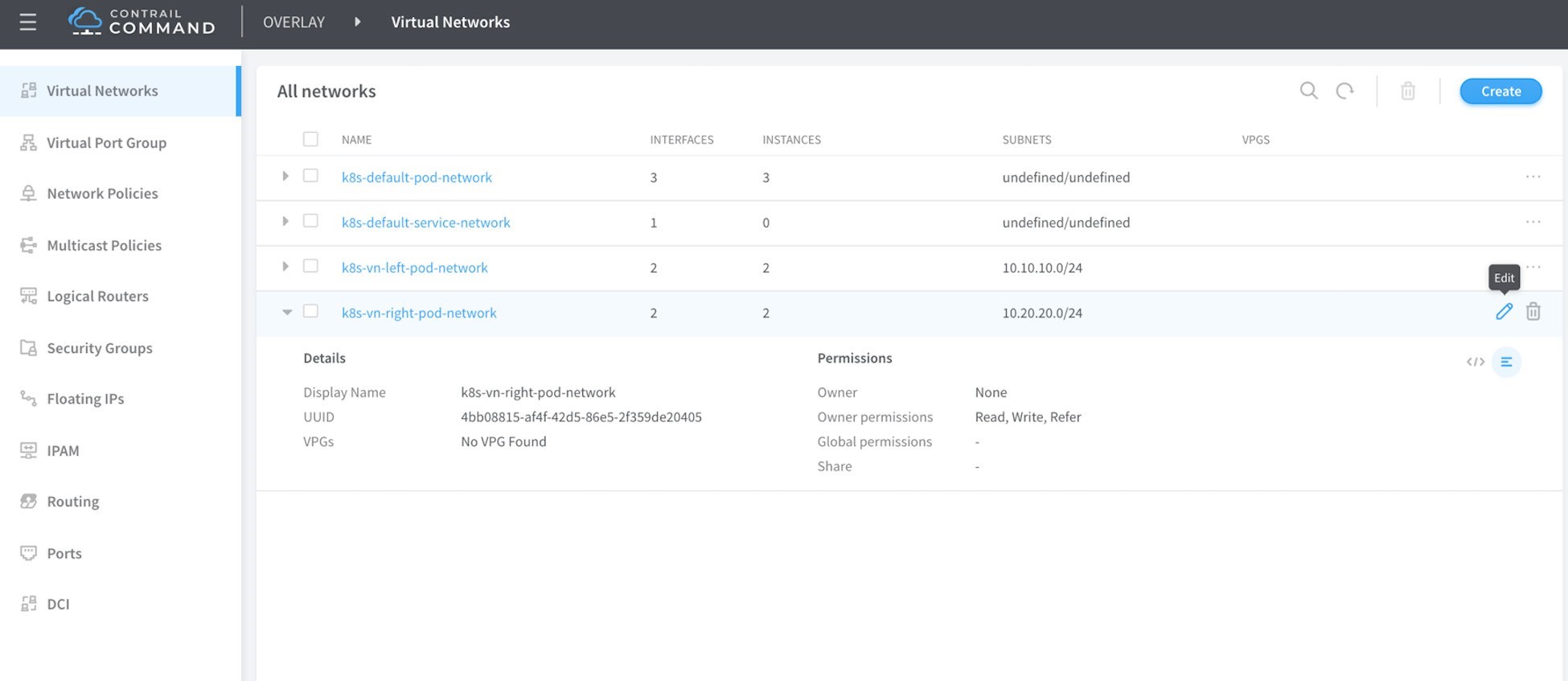
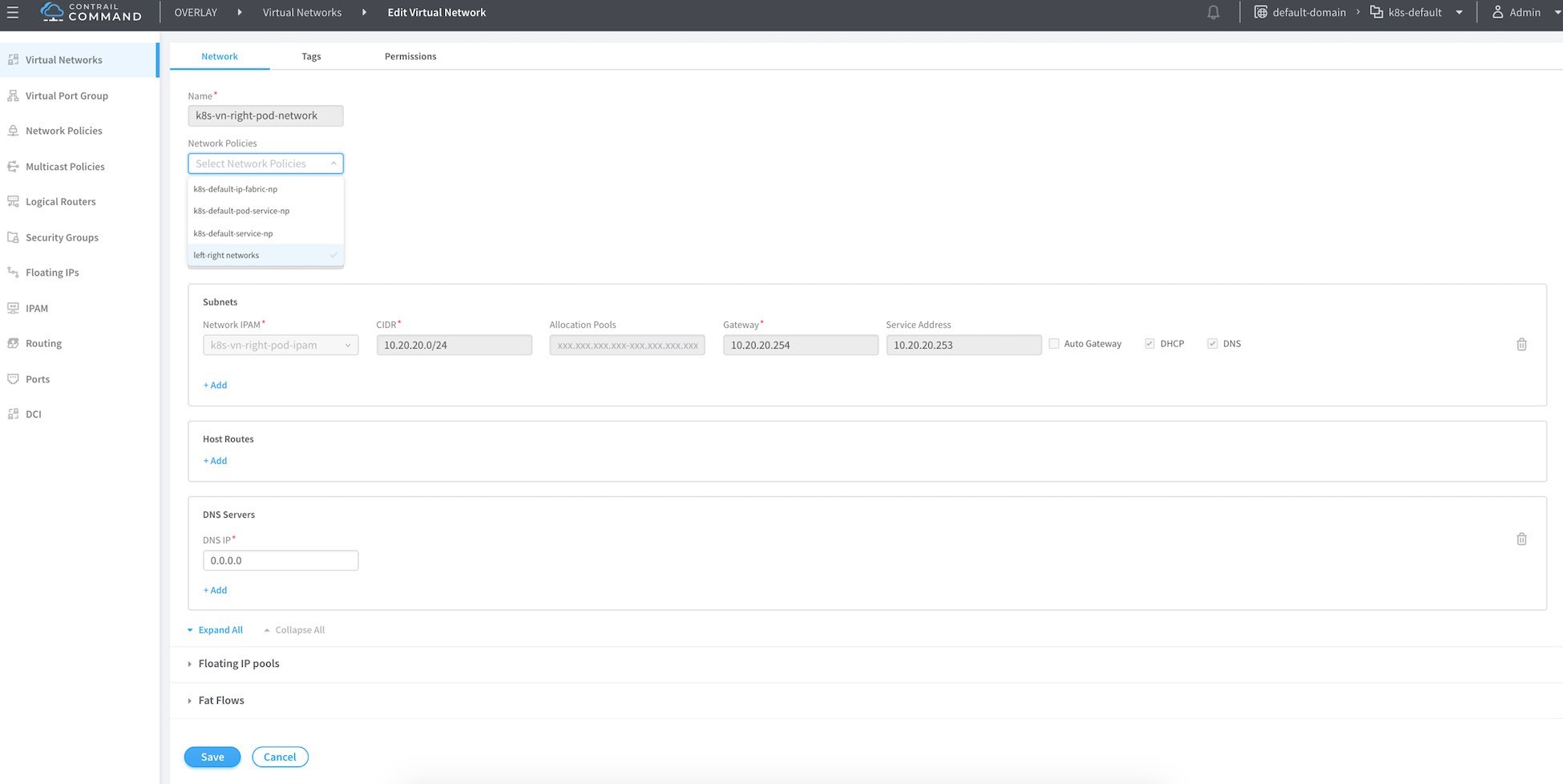
To attach this network policy to the network click on Virtual Network in the left-most column and select the left network and edit.
In Network Policies select the network policy you just created from the drop-down menu list, and then click Save. Do the same for the right network.
Verify Service Chaining
Now let’s verify the effect of this service changing on routing. From the Contrail Controller module control node (http://10.85.188.16:8143 in our setup), select Monitor > Infrastructure > Virtual Router then select the node that hosts the pod , in our case Cent22.local, then select the Routes tab and select the left VRF.
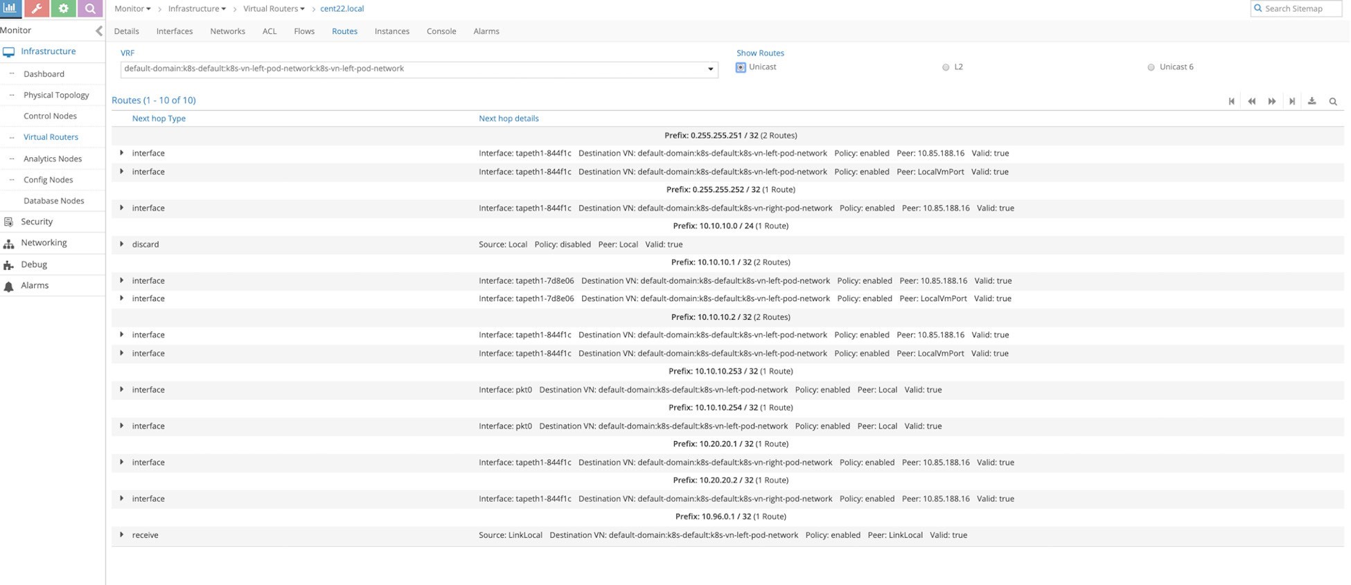
You can see that the right network host routes have been leaked to the left network (10.20.20.1/32, 10.20.20.2/32 in this case).
Now let’s ping the right pod from the left pod to see the session created on the cSRX:
Security Policy
Create a security policy on the cSRX to allow only HTTP and HTTPS:
The ping fails because the policy on the cSRX drops it:
root@csrx1-sc> show log syslog | last 20
Jun 14 23:04:01 csrx1-sc flowd-0x2[374]: RT_FLOW: RT_FLOW_SESSION_DENY:
session denied 10.10.10.1/8-
>10.20.20.1/575 0x0 icmp 1(8) deny-ping trust untrust UNKNOWN UNKNOWN
N/A(N/A) ge-0/0/1.0 No policy reject 5394 N/A N/A -1 Jun 14 23:04:02 csrx1-sc
flowd-0x2[374]: RT_FLOW: RT_FLOW_SESSION_DENY: session denied
10.10.10.1/9-
>10.20.20.1/575 0x0 icmp 1(8) deny-ping trust untrust UNKNOWN UNKNOWN
N/A(N/A) ge-0/0/1.0 No policy reject 5395 N/A N/A -1 Try to send http traffic
from the left to the right POD and verify the session status on the CSRX
root@left-ubuntu-sc:/# wget 10.20.20.1
--2019-06-14 23:07:34-- http://10.20.20.1/
Connecting to
10.20.20.1:80... connected.
 HTTP request sent,
awaiting response... 200
OK Length: 11510 (11K)
[text/html]
Saving to: 'index.html.4'

100%[=============================
=========>] 11,510				--.-K/s
in 0s
2019-06-14 23:07:34 (278 MB/s) - 'index.html.4' saved [11510/11510]
And in the cSRX we can see the session creation:
root@csrx1-sc> show log syslog | last 20
Jun 14 23:07:31 csrx1-sc flowd-0x2[374]:
csrx_l3_add_new_resolved_unicast_ nexthop:
Adding resolved unicast NH. dest: 10.20.20.1,
proto v4 (peer initiated)
Jun 14 23:07:31 csrx1-sc flowd-0x2[374]:
csrx_l3_add_new_resolved_unicast_ nexthop:
Sending resolve request for stale ARP entry (b).
NH: 5507 dest: 10.20.20.1
Jun 14 23:07:34 csrx1-sc flowd-0x2[374]: RT_FLOW:
RT_FLOW_SESSION_CREATE: session created 10.10.10.1/47190->10.20.20.1/80
0x0 junos- http 10.10.10.1/47190->10.20.20.1/80 0x0 N/A N/A N/A N/A 6 only-http-s
trust untrust 5434 N/A(N/A) ge-
0/0/1.0 UNKNOWN UNKNOWN UNKNOWN N/A N/A -1
Jun 14 23:07:35 csrx1-sc flowd-0x2[374]: RT_FLOW: RT_FLOW_SESSION_CLOSE:
session closed TCP FIN: 10.10.10.1/47190-
>10.20.20.1/80 0x0 junos-http 10.10.10.1/47190->10.20.20.1/80 0x0 N/A N/A N/A N/A 6
only-
http-s trust untrust 5434 14(940) 12(12452) 2 UNKNOWN UNKNOWN N/A(N/A) ge-
0/0/1.0 UNKNOWN N/A N/A -1