ON THIS PAGE
Contrail Multiple Interface Pod
Typically each pod in the Kubernetes cluster has only one network interface (except the loopback interface). In reality, there are scenarios where multiple interfaces are required. For example, a VNF (virtualized network function) typically needs a left, right, and optionally, a management interface to complete network functions. A pod may require a data interface to carry the data traffic, and a management interface for the reachability detection. Service providers also tend to keep the management and tenant networks independent for isolation and management purposes. Multiple interfaces provide a way for containers to be simultaneously connected to multiple devices in multiple networks.
Contrail as a CNI
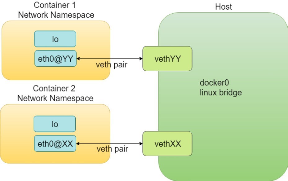
In container technology, a veth (virtual Ethernet) pair functions pretty much like a virtual cable that can be used to create tunnels between network namespaces. One end of it is plugged in the container and the other end is in the host or docker bridge namespace.
A Contrail CNI plugin is responsible for inserting the network interface (that is one end of the veth pair) into the container network namespace and it will also make all the necessary changes on the host, like attaching the other end of the veth into a bridge, assigning IP, configuring routes, and so on.
There are many such CNI plugin implementations that are publicly available today. Contrail is one of them and it is our favorite. For a comprehensive list check https://github.com/containernetworking/cni.
Another CNI plugin, multus-cni, enables you to attach multiple network interfaces to pods. Multiple-network support of multus-cni is accomplished by Multus calling multiple other CNI plugins. Because each plugin will create its own network, multiple plugins allow the pod to have multiple networks. One of the main advantages that Contrail provides, compared to mutus-cni, and all other current implementations in the industry, is that Contrail provides the ability to attach multiple network interfaces to a Kubernetes pod by itself, without having to call in any other plugins. This brings support to a truly multi-homed pod.
Network Attachment Definition CRD
Contrail CNI follows the Kubernetes CRD (Custom Resource Definition) Network Attachment Definition to provide a standardized method to specify the configurations for additional network interfaces. There is no change to the standard Kubernetes upstream APIs, making the implementation with the most compatibilities.
In Contrail, the Network Attachment Definition CRD is created by contrail-kube-manager(KM). When booted up, KM validates if a network CRD network-attachment-definitions.k8s.cni.cncf.io is found in the Kubernetes API server, and creates one if it isn’t.
Here is a CRD object YAML file:
In the Contrail Kubernetes setup, the CRD has been created and can be verified:
$ kubectl get crd
			NAME				CREATED AT
network-attachment-definitions.k8s.cni.cncf.io 2019-06-07T03:43:52Z
Using this new kind of Network-Attachment-Definition created from the above CRD, we now have the ability to create a virtual network in Contrail Kubernetes environments.
To create a virtual network from Kubernetes, use a YAML template like this:
Like many other standard Kubernetes objects, you specify the virtual network name, the namespace under metadata, and the annotations that are used to carry additional information about a network. In Contrail, the following annotations are used in the NetworkAttachmentDefinition CRD to enable certain attributes for the virtual network:
opencontrail.org/cidr: This CIDR defines the subnet for a virtual network.
opencontrail.org/ip_fabric_forwarding: This flag is to enable/disable the ip fabric forwarding feature.
opencontrail.org/ip_fabric_snat: This is a flag to enable/disable the ip fabric snat feature.
In Contrail, the ip-fabric-forwarding feature enables IP fabric-based forwarding without tunneling for the virtual network. When two ip_fabric_forwrding enabled virtual networks communicate with each other, the overlay traffic will be forwarded directly using the underlay.
With the Contrail ip-fabric-snat feature, pods that are in the overlay can reach the Internet without floating IPs or a logical router. The ip-fabric-snat feature uses compute node IP for creating a source NAT to reach the required services.
Note that ip fabric forwarding and ip fabric snat features are not covered in this book.
Alternatively, you can define a new virtual network by referring an existing virtual network:
In this book we use the first template to define our virtual networks in all examples.
Multiple Interface Pod
With multiple virtual networks created, you can attach (you could also say plug, or insert) any of them into a pod, with the pod’s YAML file like this:
Or, another valid format:
You’ve probably noticed that pods in a namespace can not only refer to the networks defined in the local namespace, but also the networks created on other namespaces using their fully scoped name. This is very useful. The same network does not have to be duplicated again and again in every namespace that needs it. It can be defined once and then referred to everywhere else.
We’ve gone through the basic theories and explored the various templates, so let’s get a working example in the real world. Let’s start by creating two virtual networks, examining the virtual network objects, then create a pod and attach the two virtual networks into it. We’ll conclude by examining the pod interfaces and the connectivity with other pods sharing the same virtual networks.
Here is the YAML file of the two virtual networks (vn-left-1 and vn-right-1):
Now create both virtual networks:
$ kubectl apply -f vn-left-1.yaml
networkattachmentdefinition.k8s.cn
i.cncf.io/vn-left-1 created


$ kubectl apply -f vn-right-1.yaml
networkattachmentdefinition.k8s.cn
i.cncf.io/vn-right-1 created
Examine the virtual networks:
$ kubectl get network-attachment-
definitions.k8s.cni.cncf.io NAME
					AGE
			vn-left-1		3s
			vn-right-1		10s
$ kubectl get network-attachment-
definitions.k8s.cni.cncf.io vn-left-1 -o yaml
apiVersion: k8s.cni.cncf.io/v1
kind:
NetworkAttachment
Definition metadata:
annotations:
kubectl.kubernetes.io/last-applied-configuration: |
		{"apiVersion":"k8s.cni.cncf.io/v1","kind":"NetworkAttachmentDefinition","metadata
	":{"annotations":{"opencontrail.org/cidr":"10.10.10.0/24","op
	encontrail.org/ip_fabric_forwarding":"false"},"name":"vn-left-1","namespace":"ns-user-
1"},"spec":{"config":"{ \"cniVersion\": \"0.3.0\", \"type\":
\"contrail-k8s-cni\" }"}} opencontrail.org/cidr:
10.10.10.0/24
opencontrail.org/ip_fabric_
forwarding: "false"
creationTimestamp: 2019-06-13T14:17:42Z
generation: 1
name: vn-left-1
namespace: ns-user-1
resourceVersion: "777874"
selfLink: /apis/k8s.cni.cncf.io/v1/namespaces/ns-user-
1/network-attachment-definitions/vn-left-1 uid:
01f167ad-8de6-11e9-bbbf-0050569e6cfc
spec:
config: '{ "cniVersion": "0.3.0", "type": "contrail-k8s-cni" }'
The virtual networks are created, as expected. Nothing much exciting here but, if you log in to the Contrail UI, you will see something unexpected in the next screen capture, Figure 2.
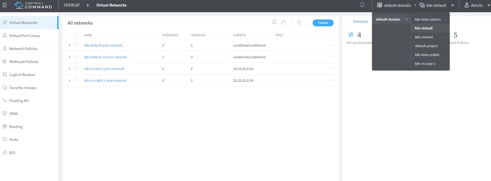
Make sure you select the correct project, in this case it is k8s-default.
And what you’ll find is the lack of any virtual network with the exact name of vn-left-1 or vn-right-1 in the UI. Instead, there two virtual networks, named k8s-vn-left-1-pod-network and k8s-vn-right-1-pod-network.
There is nothing wrong here. What happened is whenever a virtual network gets created from Kubernetes, Contrail automatically adds the Kubernetes cluster name (by default k8s) as a prefix to the virtual network name that you give in your network YAML file, and a suffix -pod-network in the end. This makes sense because we know a virtual network can be created by different methods and with these extra keywords embedded in the name, it’s easier to tell how the virtual network was created (from Kubernetes or manually from the UI) and what will it be used for. Also, potential virtual network name conflicts can be avoided when working across multiple Kubernetes clusters.
Here is YAML file of a pod with multiple virtual networks:
In pod annotations under metadata, insert two virtual networks: vn-left-1 and vn-right-1. Now, guess how many interfaces the pod will have on bootup? You might think two because that is what we specified in the file. Let’s create the pod and verify:
$ kubectl get pod -o wide
NAME	READY  STATUS    RESTARTS AGE IP	NODE NOMINATED NODE
webserver-mv  1/1    Running 0	20s 10.47.255.238 cent222 <none>

$ kubectl describe
pod webserver-mv
	Name:	webserver-mv
Namespace:	ns-user-1
Priority:	0
PriorityClassName: <none>
Node:	cent222/10.85.188.20
Start Time:		Wed, 26 Jun 2019 12:51:30 -0400
Labels:	app=webserver-mv
Annotations:		k8s.v1.cni.cncf.io/network-status: [
{
"ips": "10.10.10.250",
"mac": "02:87:cf:6c:9a:98",
"name": "vn-left-1"
},
{
"ips": "10.47.255.238",
"mac": "02:87:98:cc:4e:98",
"name": "cluster-wide-default"
},
{
"ips": "20.20.20.1",
"mac": "02:87:f9:f9:88:98",
"name": "vn-right-1"
}
]
k8s.v1.cni.cncf.io/networks: [
{ "name": "vn-left-1" }, { "name": "vn-right-1" } ] kubectl.kubernetes.io/last-applied-configuration:
{"apiVersion":"v1","kind":"Pod","metadata":
{"annotations":{"k8s.v1.cni.cncf.io/networks":"[
{ \"name\": \"vn-left-1\" }, { \"name\": \"vn-...
Status:	Running
IP:	10.47.255.238
...<snipped>...
In Annotations, under k8s.v1.cni.cncf.io/network-status, you can see a list […], which has three items, each represented by a curly brace {} of key-value mappings. Each curly brace includes information about one interface: the allocated IP, the MAC, and the virtual network it belongs to. So you will end up having three interfaces created in the pod instead of two.
Notice the second item stating the IP address 10.47.255.238. It is the interface attached to the default pod network named cluster-wide-default, which is created by the system. You can look at the default pod network as a management network because it is always up and running in every pod’s network namespace. Functionally, it’s not much different from the virtual network you created, except that you can’t delete it.
Let’s log in to the pod, list the interfaces, and verify the IP and MAC addresses:
$ kubectl exec -it webserver-mv sh
/ # ip a
1: lo: <LOOPBACK,UP,LOWER_UP> mtu 65536 qdisc noqueue qlen 1000
link/loopback
00:00:00:00:00:00 brd
00:00:00:00:00:00 inet
127.0.0.1/8 scope host lo
	valid_lft forever preferred_lft forever
37: eth0@if38:
	<BROADCAST,MULTICAST,UP,LOWER_UP,M-
	DOWN> mtu 1500 qdisc noqueue link/ether
	02:87:98:cc:4e:98 brd ff:ff:ff:ff:ff:ff
	inet 10.47.255.238/12
		scope global eth0
		valid_lft forever
		preferred_lft forever
	39: eth1@if40:
		<BROADCAST,MULTICAST,UP,LOWER_UP,M-
		DOWN> mtu 1500 qdisc noqueue link/ether
		02:87:cf:6c:9a:98 brd ff:ff:ff:ff:ff:ff
		inet 10.10.10.250/24
			scope global eth1
			valid_lft forever
			preferred_lft forever
41: eth2@if42:
		<BROADCAST,MULTICAST,UP,LOWER_UP,M-
		DOWN> mtu 1500 qdisc noqueue link/ether
		02:87:f9:f9:88:98 brd ff:ff:ff:ff:ff:ff
		inet 20.20.20.1/24
			scope global eth2
			valid_lft forever
			preferred_lft forever
You can see one lo interface and three interfaces plugged by Contrail CNI, each with the IP allocated from the corresponding virtual network. Also notice the MAC addresses match what we’ve seen in the kubectl describe command output.
Having the MAC address in the annotations can be useful under certain cases. For example, in the service chaining section, you will run into a scenario where you have to use the MAC address to locate the proper interface, so that you can assign the right podIP that Kubernetes allocated from a virtual network. Read on for more details.
You’ll see the multiple-interfaces pod again in the example where the pod will be based on a Juniper cSRX image instead of a general Docker image. The basic idea remains the same.