Contrail Firewall Policy
In Chapter 4, you were given the Kubernetes to Contrail Object Mapping Figure, which is repeated here as Figure 1.
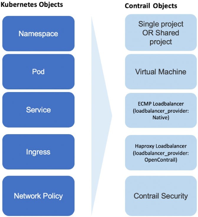
This mapping highlights Contrail’s implementation of Kubernetes core objects: Namespace, pod, Service, Ingress, and Network Policy. From Chapters 4 through 7 we’ve pretty much explored everything in Figure 1 except Network Policy.
In this chapter we’ll focus on the Network Policy implementation in Contrail. First we’ll introduce the Contrail firewall, which is the feature used to implement Kubernetes network policy; then we’ll set up a test case to verify how Kubernetes network policy works in Contrail; then, based on the test results, we’ll explore the Contrail firewall policies and their rules in detail in order to understand the Contrail implementation, as well as the mapping between the two objects in the object mapping diagram of Figure 1.
Introducing Contrail Firewall
In Chapter 3 we introduced the Kubernetes network policy concept. We went through the YAML file definition in detail and created a network policy based on it. We’ve also mentioned that simply creating network policy objects won’t have any effect, unless the Kubernetes networking implementation supports it. Contrail, as a Kubernetes CNI, implements the Kubernetes networking and supports the Kubernetes network policy through Contrail firewall. That is the focus of this chapter - we’ll demonstrate how network policy works in the Contrail environment via Contrail firewall.
First let’s review some important concepts in Contrail.
Inter-VN Routing.
In Contrail, virtual networks are isolated by default. That means workloads in VN1 cannot communicate with workloads in another VN2. To allow inter-virtual network communications between VN1 to VN2, Contrail network policy is required. Contrail network policy can also provide security between two virtual networks by allowing or denying specified traffic.
Contrail Network Policy.
A Contrail network policy is used to permit inter-virtual network communication and to modify intra-virtual network traffic. It describes which traffic is permitted or not between virtual networks. By default, without a Contrail network policy, intra-virtual network communication is allowed, but inter-virtual network traffic is denied. When you create a network policy you must associate it with a virtual network for it to have any effect.
Don’t confuse Contrail network policy with Kubernetes network policy. They are two different security features and they work separately.
Security Group(SG).
A security group, often abbreviated as a SG, is a group of rules that allow a user to specify the type of traffic that is allowed or not allowed through a port. When a VM or pod is created in a virtual network, a SG can be associated with the VM when it is launched. Unlike Contrail network policy, which is configured globally and associated to the virtual networks, the SG is configured on the per-port basis and it will take effect on the specific vRouter flows that is associated with the VM port.
The Limitation of Contrail Network Policy and SG
In modern Contrail cloud environments, sometimes it is hard to use only the existing network policy and security group to achieve desired security goals. For example, in cloud environments, workloads may move from one server to another and so most likely the IP is often changing. Just relying on IP addresses to identify the endpoints to be protected is painful. Instead, users must leverage application level attributes to manipulate policies, so that the policies don’t need to be updated every time a workload moves and the associated network environment changes. Also, in production, a user might need to group workloads based on combinations of tags, which is hard to translate into the existing language of a network policy or SG.
Contrail Firewall Security Policy.
This chapter introduces another important feature: Contrail firewall security policy.
Contrail firewall security policy allows decoupling of routing from security policies,vand provides multidimension segmentation and policy portability, while significantly enhancing user visibility and analytics functions.
In order to implement the multi-dimension traffic segmentation, Contrail firewall introduces the concept of tags. Tags are key-value pairs associated with different entities in the deployment. Tags can be pre-defined or custom/user defined. Contrail tags are pretty much the same thing as Kubernetes labels. Both are used to identify objects and workloads. As you can see, this is similar to Kubernetes network policy design, and it is natural for Contrail to use its firewall security policy to implement Kubernetes network policy. In theory, Contrail network policy or SG can be extended to do the job, but the support of tags by Contrail firewall makes it so much simpler
Sometimes Contrail firewall security policy is referred to as Contrail Security, Contrail firewall, Contrail firewall security, or simply Contrail FW.
Contrail Kubernetes Network Policy Use Case
In this section, we’ll create a use case to verify how Kubernetes network policy works in Contrail environments. We’ll start by creating a few Kubernetes namespaces and pods that are required in the test. We’ll confirm that every pod can talk to the DUT (Device Under Test) because of the default allow-any-any networking model, then create network policies and observe any changes with same traffic pattern.
Network Design
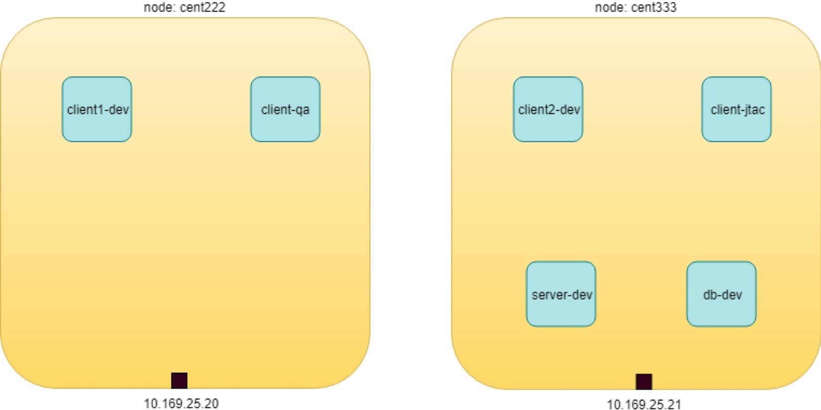
The use case design is shown in Figure 2.
In Figure 2 six nodes are distributed in three departments: dev, qa, and jtac. The dev department is running a database server (dbserver-dev) holding all valuable data collected from the customer. The design requires that no one have direct access to this db server, instead, the db server access is only allowed through another Apache frontend server in dev department, named webserver-dev. Furthermore, for security reasons, the access of customer information should only be granted to authorized clients. For example, only nodes in the jtac department, one node in dev department named client1-dev, and the source IP 10.169.25.20 can access the db via webserver. And finally, the database server dbserver-dev should not initiate any connection toward other nodes.
Lab Preparation
Here is a very ordinary, simplified network design that you can see anywhere. If we model all these network elements in the Kubernetes world, it looks like Figure 3.
Pods We need to create the following resources:
Three namespaces: dev, qa, jtac
Six pods:
Two server pods: webserver-dev, dbserver-dev
Two client pods in the same namespace as server pods: client1-dev, client2-dev
Two client pods from two different namespaces: client-qa, client-jtac
Two CIDRs:
cidr: 10.169.25.20/32, this is fabric IP of node cent222
cidr: 10.169.25.21/32, this is fabric IP of node cent333
Table 1: Kubernetes Network Policy Test Environment
NS | pod | role |
dev | client1-dev | web client |
dev | client2-dev | web client |
qa | client-qa | web client |
jtac | client-jtac | web client |
dev | webserver-dev | webserver serving clients |
dev | dbserver-dev | dbserver serving webserver |
Okay, let’s prepare the required k8s namespace and pods resources with an all-in-one YAML file defining dev, qa, and jtac namespaces:
Ideally, each pod should run with different images. And, TCP ports usually are different between a webserver and a database server. In our case, to make the test easier, we used the exact same contrail-webserver image that we’ve been using throughout the book for all the pods, so clients to webserver and webserver to database server communication all use the same port number 80 served by the same HTTP server. Also, we added a label do: policy in all pods, so that displaying all pods used in this test is also easier.
Okay and now create all the resources:
Traffic Mode Before Kubernetes Network Policy Creation
Since we have all of the namespace and pods, before we define any network policy, let’s go ahead and send traffic between clients and servers.
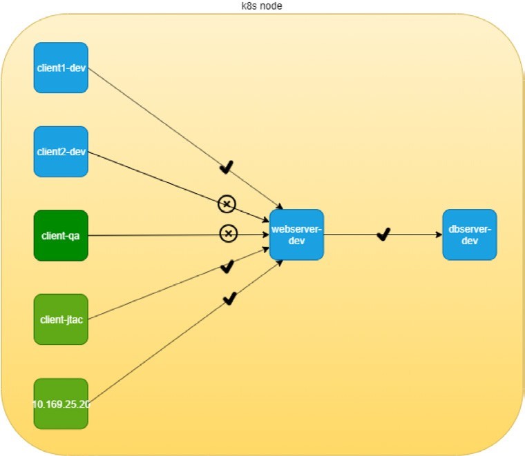
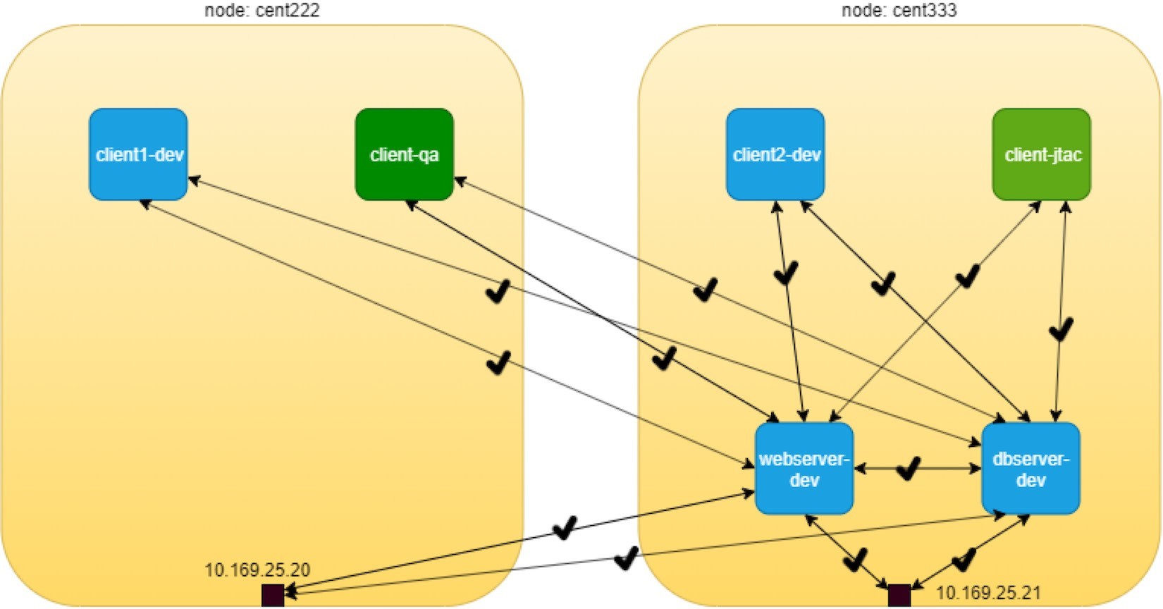
Of course, Kubernetes networking, by default, follows the allow-any-any model, so we should expect that access works between any pod, which is going to be a fully meshed access relationship. But keep in mind that the DUT in this test is webserver-dev and dbserver-dev is the one we are more interested in observing. To simplify the verification, according to our diagram, we’ll focus on accessing the server pods from the client pods, as illustrated in Figure 8.4.
The highlights of Figure 8.4 are that all clients can access the servers, following the permit-any-any model:
there are no restrictions between clients and webserver-dev pod
there are no restrictions between clients and dbserver-dev pod
And the communication between client and servers are bi-directional and symmetrical – each end can initiate a session or accept a session. These map to the egress policy and ingress policy, respectively, in Kubernetes.
Obviously, these do not meet our design goal, which is exactly why we need the Kubernetes network policy, and we’ll come to that part soon. For now, let’s quickly verify the allow-any-any networking model.
First let’s verify the HTTP server running at port 80 in webserver-dev and dbserver-dev pods:
$kubectl exec -it webserver-dev -n
 dev -- netstat -antp| grep 80 tcp	0	0
 0.0.0.0:80	   0.0.0.0:*
  LISTEN	      1/python
$kubectl exec -it dbserver-dev -n dev -- netstat -antp| grep 80
tcp	 0	0 0.0.0.0:80	 0.0.0.0:*    LISTEN	1/python
As mentioned earlier, in this test all pods are with the same container image, so all pods are running the same webserver application in their containers. We simply name each pod to reflect their different roles in the diagram.
Now we can verify accessing this HTTP server from other pods with the following commands. To test ingress traffic:
These commands trigger the HTTP requests to the webserver-dev pod from all clients and hosts of the two nodes. The -m5 curl command option makes curl wait a maximum of five seconds for the response before it claims time out. As expected, all accesses pass through and return the same output shown next.
From client1-dev:
$ kubectl exec -it client1-dev -n dev -- \
				curl http://$webserverIP | w3m -T text/html | grep -v "^$"
										Hello
								This page is served
								 by a Contrail pod
								IP address =
								10.47.255.234
								Hostname = webserver-dev
Here, w3m gets the output from curl, which returns a webpage HTML code and renders it into readable text, then send it to grep to remove the empty lines. To make the command shorter you can define an alias:
alias webpr='w3m -T text/html | grep -v "^$"'
Now the command looks shorter:
$ kubectl exec -it client1-dev -n dev -- curl http://$webserverIP | webpr
								Hello
					This page is served
					by a Contrail pod
					IP address =
					10.47.255.234
				 Hostname = webserver-dev
Similarly, you’ll get the same test results for access to dbserver-dev from any of the other pods.
Create Kubernetes Network Policy
Now let’s create the k8s network policy to implement our design. From our initial design goal, these are what we wanted to achieve via network policy:
client1-dev and pods under jtac namespace (that is jtac-dev pod) can access webserver-dev pod
webserver-dev pod (and only it) is allowed to access dbserver-dev pod
all other client pods are not allowed to access the two server pods
all other client pods can still communicate with each other
Translating these requirements into the language of Kubernetes network policy, we’ll work with this network policy YAML file:
From the network-policy definition, based on what you’ve learned in Chapter 3, you should easily be able to tell what the policy is trying to enforce in our current setup:
According to the ingress policy, the following clients can reach the webserver-dev server pod located in dev namespace:
client1-dev from dev namespace
all pods from jtac namespace, that is client-jtac pod in our setup
clients with source IP 10.169.25.20 (cent222 in our setup)
According to the egress policy, the webserver-dev server pod in dev namespace can initiate a TCP session toward dbserver-dev pod with destination port 80 to access the data.
For target pod server-dev, all other accesses are denied.
Communication between all other pods are not affected by this network policy.
Actually, this is the exact network policy YAML file that we’ve demonstrated in Chapter 3.
Let’s create the policy and verify its effect:
$ kubectl apply -f policy1-
do.yaml
 networkpolicy.networking.k8
s.io/policy1 created
$ kubectl get networkpolicies --
all-namespaces NAMESPACE
NAME	    		POD-
SELECTOR		AGE
dev	policy1 app=webserver-dev 17s
Post Kubernetes Network Policy Creation
After the network policy policy1 is created, let’s test the accessing of the HTTP server in webserver-dev pod from pod client1-dev, client-jtac , and node cent222 host:
$ kubectl exec -it client1-dev -n dev -- curl http://$webserverIP | webpr
								Hello
					This page is served
					by a Contrail pod
 					IP address =
					10.47.255.234
					Hostname = webserver-dev
The access from these two pods to webserver-dev is okay and that is what we want. Now, if we repeat the same test from the other pod client2-dev, client-qa and another node cent333 now get timed out:
$ kubectl exec -it client2-dev -n dev --
 curl http://$webserverIP -m 5 curl: (28)
 Connection timed out after 5000
milliseconds
command terminated with exit code 28
$ kubectl exec -it client-jtac -n jtac --
 curl http://$webserverIP -m 5 curl: (28)
 Connection timed out after 5000
 milliseconds
command terminated with exit code 28
$ curl http://$webserverIP -m 5
curl: (28) Connection timed out after 5000 milliseconds
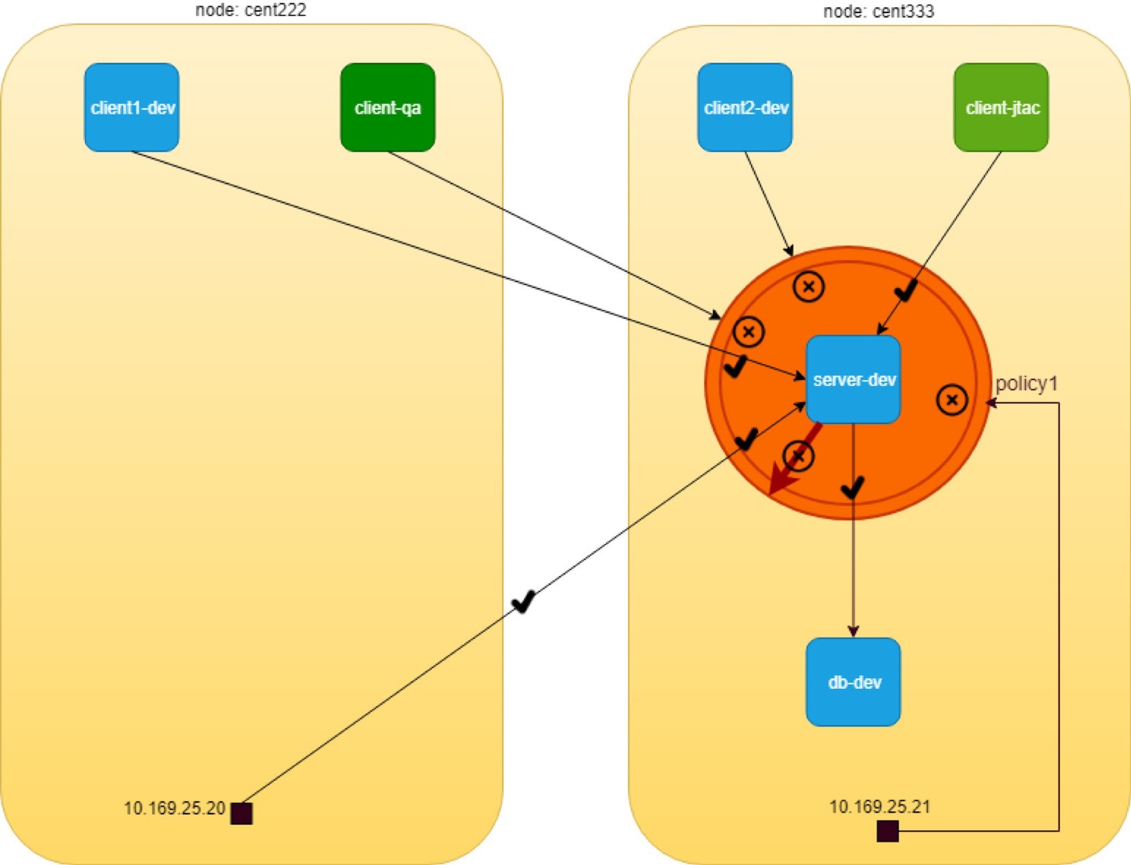
The new test results after the network policy is applied are illustrated in Figure 5.
A detail of the network policy object tells the same things:
$ kubectl describe
netpol -n dev policy1
Name:	policy1
Namespace: dev
Created on: 2019-09-29 21:21:14 -0400 EDT
Labels:	<none>
Annotations: kubectl.kubernetes.io/last-applied-configuration:
			{"apiVersion":"networking.k8s.io/v1",
			"kind":"NetworkPolicy",
			 "metadata":{"annotations":{},"name":
			"policy1","namespace":"dev"},
			"spec":{"egre...
Spec:
PodSelector:
app=webserver-dev
Allowing ingress
traffic:     #<--- To
Port: 80/TCP
From:
IPBlock:
		CIDR: 10.169.25.20/32
		Except:
From:
		NamespaceSelector:
project=jtac
From:
		PodSelector:
 app=client1-dev
Allowing egress
traffic:
To Port:
80/TCP To:
PodSelector:
app=dbserver-dev
Policy Types:
Ingress, Egress
From the above exercise, we can conclude that k8s network policy works as expected in Contrail.
But our test is not done yet. In the network policy we defined both ingress and egress policy, but so far from webserver-dev pod’s perspective we’ve only tested that the ingress policy of policy1 works successfully. Additionally, we have not applied any policy to the other server pod dbserver-dev. According to the default allow any policy, any pods can directly access it without a problem. Obviously, this is not what we wanted according to our original design. Another ingress network policy is needed for dbserver-dev pod, and finally, we need to apply an egress policy to dbserver-dev to make sure it can’t connect to any other pods. So there are at least three more test items we need to confirm, namely:
Test the egress policy of policy1 applied to webserver-dev pod;
Define and test ingress policy for dbserver-dev pod;
Define and test egress policy for dbserver-dev pod. Let’s look at the egress policy of policy1 first.
Egress Policy on webserver-dev Pod
Here’s the test on egress traffic:
The result shows that only access to dbserver-dev succeeds while other egress access times out:
$ kubectl exec -it webserver-dev -n dev -- curl $dbserverIP -m5 | webpr
									Hello
						This page is served
						by a Contrail pod
 						IP address =
						10.47.255.233
						Hostname = dbserver-dev
$ kubectl exec -it webserver-dev -n
dev -- curl 10.47.255.232 -m5 curl:
 (28) Connection timed out after 5001
 milliseconds command terminated
with exit code 28
Network Policy on dbserver-dev Pod
So far, so good. Let’s look at the second test items, ingress access to dbserver-dev pod from other pods other than webserver-dev pod. Test the egress traffic:
All pods can access dbserver-dev pod directly:
$ kubectl exec -it client1-dev -n dev -- curl http://$dbserverIP -m5 | webpr
									Hello
							This page is served
							by a Contrail pod
							IP address =
							10.47.255.233
							Hostname = dbserver-dev
Our design is to block access from all pods except the webserver-dev pod. For that we need to apply another policy. Here is the YAML file of the second policy:
This network policy, policy2, is pretty much like the previous policy1, except that it looks simpler – the policy Types only has Ingress in the list so it will only define an ingress policy. And that ingress policy defines a whitelist using only a podSelector. In our test case, only one pod webserver-dev has the matching label with it so it will be the only one allowed to initiate the TCP connection toward target pod dbserver-dev on port 80. Let’s create the policy policy2 now and verify the result again:
$ kubectl exec -it webserver-dev -n dev -- curl
								 http://$dbserverIP -m5 | webpr
								Hello
						This page is served
						by a Contrail pod
						IP address =
						10.47.255.233
						Hostname =
						dbserver-dev
$ kubectl exec -it client1-dev -n dev -- curl
http://$dbserverIP -m5 | webpr command
terminated with exit code 28
curl: (28) Connection timed out after 5002 milliseconds
Now the access to dbserver-dev pod is secured!
Egress Policy on dbserver-dev
Okay, just one last requirement from our design goal: server dbserver-dev should not be able to initiate any connection toward other nodes.
When you reviewed policy2, you may have wondered how we make that happen. In Chapter 3 we emphasized that network policy is whitelist-based only by design. So whatever you put in the whitelist means it is allowed. Only a blacklist gives a deny, but even with a blacklist you won’t be able to list all the other pods just to get them denied.
Another way of thinking about this is to make use of the deny all implicit policy. So assuming this sequence of policies is in current Kubernetes network policy design:
policy2 on dbserver-dev
deny all for dbserver-dev
allow all for other pods
It looks like if we give an empty whitelist in egress policy of dbserver-dev, then nothing will be allowed and the deny all policy for the target pod will come into play. The problem is, how do we define an empty whitelist:
Turns out this doesn’t work as expected:
$ kubectl exec -it dbserver-dev -n dev -- curl
								http://10.47.255.232 -m5 | webpr
								Hello
						This page is served
						by a Contrail pod
						IP address =
				 		10.47.255.232
						Hostname =
						client1-dev
Checking the policy object detail does not uncover anything obviously wrong:
$ kubectl describe netpol
policy2-tryout -n dev
Name:	policy2-tryout
Namespace: dev
Created on: 2019-10-01 17:02:18 -0400 EDT
Labels:	<none>
Annotations: kubectl.kubernetes.io/last-applied-configuration:
			{"apiVersion":"networking.k8s.io/v1",
			"kind":"NetworkPolicy",
			"metadata":{"annotations":{},"name":
			"policy2-tryout",
			"namespace":"dev"},"spec"...
Spec:
PodSelector:
app=dbserver-dev
Allowing ingress
traffic:
To Port:
80/TCP
From:
PodSelector:
app=webserver-dev
Allowing egress
traffic:
<none> (Selected pods are isolated for
egress connectivity)
						#<
--- Policy Types: Ingress
The problem is on the policyTypes. We haven’t added the Egress in, so whatever is configured in egress policy will be ignored. Simply adding - Egress in policyTypes will fix it. Furthermore, to express an empty whitelist, the egress: keyword is optional and not required. Below is the new policy YAML file:
Now delete the old policy2 and apply this new policy. Requests from dbserver-dev to any other pods (for example pod client1-dev) will be blocked:
$ kubectl exec -it dbserver-dev -n dev --
curl http://10.47.255.232 | webpr
command terminated with exit code 28
curl: (7) Failed to connect to 10.47.255.232 port 80: Connection timed out
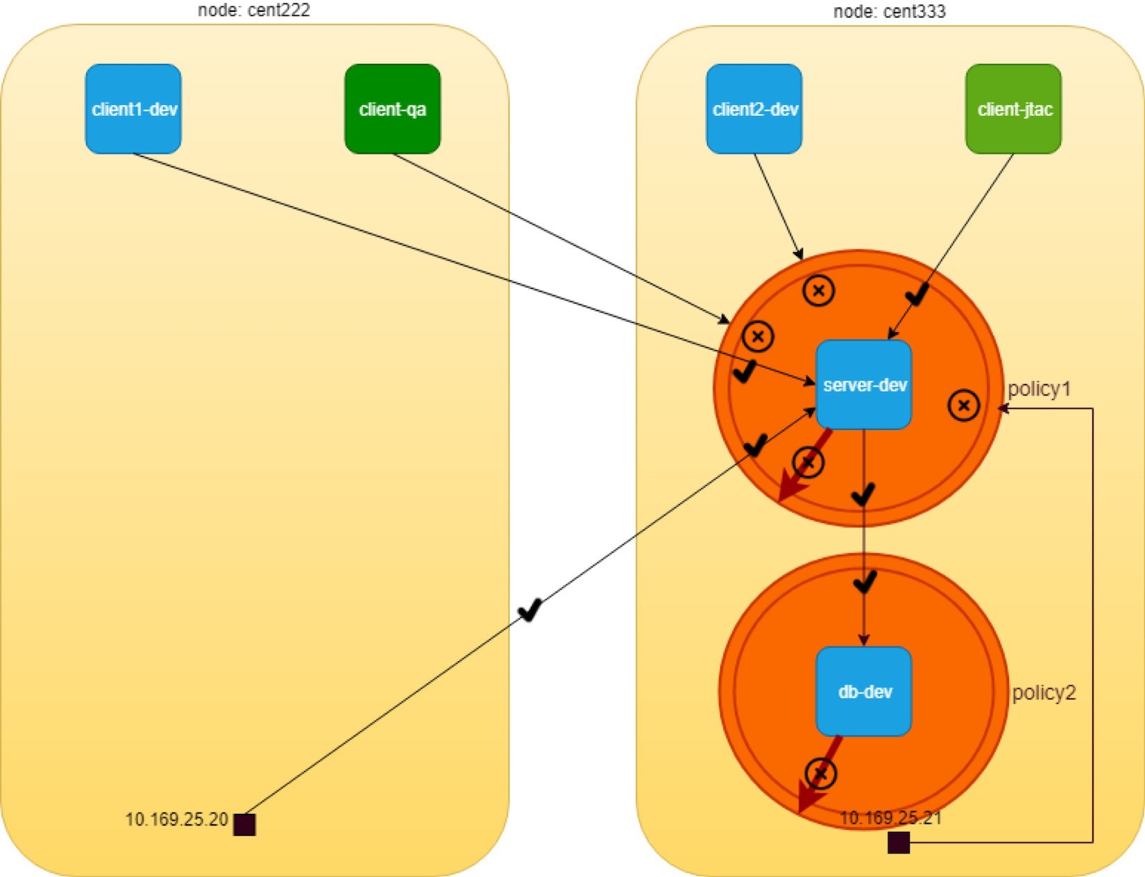
And here is the final diagram illustrating our network policy test result in Figure 6.
The Drop Action in Flow Table
Before concluding the test, let’s take a look at the vRouter flow table when traffic is dropped by the policy. On node cent333 where pod dbserver-dev is located:
$ docker exec -it vrouter_vrouter-agent_1
flow --match 10.47.255.232:80 Flow
table(size 80609280, entries 629760)

Entries: Created 33 Added 33 Deleted 30 Changed 54Processed 33 Used Overflow entries 0
(Created Flows/CPU: 7 9 11 6)(oflows 0)

Action:F=Forward, D=Drop N=NAT(S=SNAT, D=DNAT,
Ps=SPAT, Pd=DPAT, L=Link Local Port)
Other:K(nh)=Key_Nexthop, S(nh)=RPF_Nexthop
Flags:E=Evicted, Ec=Evict Candidate, N=New Flow,
M=Modified Dm=Delete Marked TCP(r=reverse):S=SYN,
 F=FIN, R=RST, C=HalfClose, E=Established, D=Dead


Listing flows matching ([10.47.255.232]:80)

Index				Source:Port/Destination:Port	 		Proto(V)
158672<=>495824	 	10.47.255.232:80	6 (5) 		10.47.255.233:42282
(Gen: 1, K(nh):59, Action:D(Unknown),
Flags:, TCP:Sr, QOS:-1, S(nh):63, Stats:0/0,
SPort 54194, TTL 0, Sinfo 0.0.0.0)


495824<=>158672			10.47.255.233:42282	6 (5)			10.47.255.232:80
(Gen: 1, K(nh):59, Action:D(FwPolicy),
Flags:, TCP:S, QOS:-1, S(nh):59, Stats:3/222,
SPort 52162, TTL 0, Sinfo 8.0.0.0)
The Action:D is set to D(FwPolicy), which means Drop due to the firewall policy. Meanwhile, in the other node cent222, where the pod client1-dev is located, we don’t see any flow generated, indicating the packet does not arrive:
$ docker exec -it vrouter_vrouter-agent_1
flow --match 10.47.255.233 Flow
table(size 80609280, entries 629760)


 ......

 Listing flows matching ([10.47.255.233]:*)

Index	Source:Port/Destination:Port	Proto(V)
Contrail Implementation Details
We’ve reiterated that Contrail implements Kubernetes network policy with a Contrail firewall security policy. You also know that Kubernetes labels are exposed as tags in Contrail. These tags are used by Contrail security policy to implement specified Kubernetes policies. Tags will be created automatically from Kubernetes objects labels or created manually in the UI.
In this section we’ll take a closer look at the Contrail firewall policies, policy rules, and the tags. In particular, we’ll examine the mapping relationships between the Kubernetes objects that we created and tested in the last section, and the corresponding Contrail objects in Contrail firewall system.
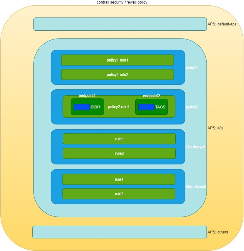
Contrail firewall is designed with a hierarchical structure:
The top level object is named Application Policy Set, abbreviated as APS.
APS has firewall policies.
Firewall policy has firewall rules.
Firewall rules have the endpoints.
Endpoints can be identified via tags or address groups (CIDRs).
The structure is illustrated in Figure 7.
Construct Mappings
Kubernetes network policy and Contrail firewall policy are two different entities in terms of the semantics of the network policy in which each is specified. In order for Contrail firewall to implement Kubernetes network policy, Contrail needs to implement the one-to-one mapping for a lot of data construct from Kubernetes to Contrail firewall. These data constructs are the basic building blocks of Kubernetes network policy and the corresponding Contrail firewall policy.
Table 2 lists Kubernetes network policy constructs and the corresponding constructs in Contrail:
Table 2: K8s Network Policy And Contrail Firewall Construct Mapping
K8s Network Policy Construct | Contrail Firewall Construct |
Cluster Name | APS (one per k8s cluster) |
Network Policy | Firewall Policy (one per k8s network policy) |
Ingress and Egress policy rule | Firewall Rule (one per k8s ingress/egress policy rule) |
CIDR | Address Group(one per k8s network policy CIDR ) |
Label | Tag (one for each k8s label) |
Namespace | Custom Tag (one for each namespace) |
The contrail-kube-manager, the KM, as we’ve read many times earlier in this book, does all of the translations between the two worlds. Basically the following will happen in the context of Kubernetes network policy:
The KM will create an APS with a Kubernetes cluster name during its initialing process. Typically the default Kubernetes cluster name is k8s, so you will see an APS with the same name in your cluster.
The KM registers to kube-apiserver to watch the network policies events.
Whenever a Kubernetes network policy is created, a corresponding Contrail firewall policy will be created with all matching firewall rules and network endpoints.
For each label created in a Kubernetes object there will be a corresponding Contrail tag created.
Based on the tag, the corresponding Contrail objects (VN, pods, VMI, projects, etc.) can be located.
Contrail will then apply the Contrail firewall policies and rules in the APS on the Contrail objects, this is how the specific traffic is permitted or denied.
The APS can be associated to different Contrail objects, for example:
VMI (virtual machine interface)
VM (virtual machine) or pods
VN (virtual network)
project
In Contrail Kubernetes cluster, the APS is associated to virtual network. Whenever traffic goes on those networks, firewall policies associated on the APS would be evaluated and respective action would be taken for the traffic.
In the previous section, we created two Kubernetes network policies in our use case. Now let’s explore the Contrail objects that are created for these Kubernetes network policies.
Application Policy Set (APS)
As mentioned, contrail-kube-manager will create an APS using the Kubernetes cluster name during the initialization stage. In Chapter 3, when we introduced Contrail Namespaces and Isolation, we learned the cluster name is k8s by default in Contrail. Therefore the APS name will also be k8s in the Contrail UI shown in Figure 8.
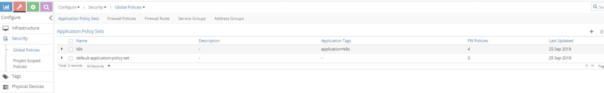
There is one more APS default-application-policy-set that is created by default.
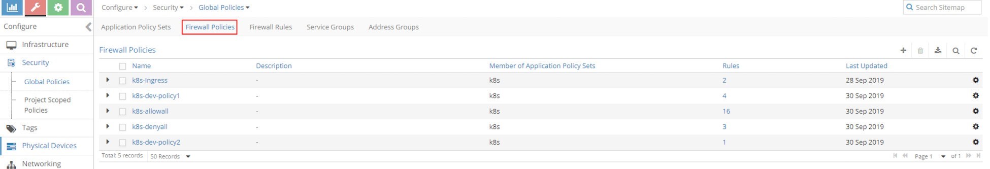
Policies
Now click on Firewall Policies to display all firewall polices in the cluster. In our test environment, you will find the following policies available:
k8s-dev-policy1
k8s-dev-policy2
k8s-denyall
k8s-allowall
k8s-Ingress
Contrail Firewall Policy Naming Convention
The k8s-dev-policy1 and k8s-dev-policy2 policies are what we’ve created. Although they look different from the object names we gave in our YAML file, it is easy to tell which is which. When KM creates the Contrail firewall policies based on the Kubernetes network policies, it prefixes the firewall policy name with the cluster name, plus the namespace, in front of our network policy name:
<cluster name>-<namespace-name>-<kubernetes network policy name>
This should sound familiar. Earlier we showed how KM names the virtual network in Contrail UI after the Kubernetes virtual network objects name we created in the YAML file.
The K8s-ingress firewall policy is created for the ingress loadbalancer to ensure that ingress to works properly in Contrail. A detailed explanation is beyond the scope of this book.
But the bigger question is, why do we still see two more firewall policies here, since we have never created any network policies like allowall, or denyall?
Well, remember when we introduced Kubernetes network policy back in Chapter 3, and mentioned that Kubernetes network policy uses a whitelist method and the implicit deny all and allow all policies? The nature of the whitelist method indicates deny all action for all traffic other than what is added in the whitelist, while the implicit allow all behavior makes sure a pod that is not involved in any network policies can continue its allow-any-any traffic model. The problem with Contrail firewall regarding this implicitness is that by default it follows a deny all model - anything that is not explicitly defined will be blocked. That is why in Contrail implementation, these two corresponding implicit network policies are honored by two explicit policies generated by the KM module.
One question may be raised at this point. With multiple firewall policies, which one should be applied and evaluated first and which ones later? In other words, in what sequence will Contrail apply and evaluate each policy – a firewall policy evaluation with a different sequence will lead to completely different result. Just imagine these two sequences denyall - allowall versus allowall - denyall. The former gives a deny to all other pods, while the latter gives a pass The answer is the sequence number.
Sequence Number
When firewall polices in an APS are evaluated, they have to be evaluated in a certain sequence. All firewall polices and all firewall rules (we will come to this soon) in each of the policies has a sequence number. When there is a matching policy, it will be executed, and the evaluation will stop. It is again contrail-Kube-manager that allocates the right sequence number for all firewall policies and firewall rules, so that everything works in the correct order. The process is automatically done without manual intervention. You don’t have to worry about these things when you create the Kubernetes network policies.
We’ll visit sequence numbers again later, but for now let’s look at the rules defined in the firewall policy.
Firewall Policy Rules
In the following capture of the Firewall Policies list, on the right side you can see the number of Rules for each policy.
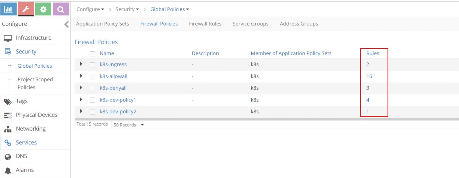
There are four rules for the k8s-dev-policy1 policy. Clicking on Rules will show the rules in detail as in Figure 11.
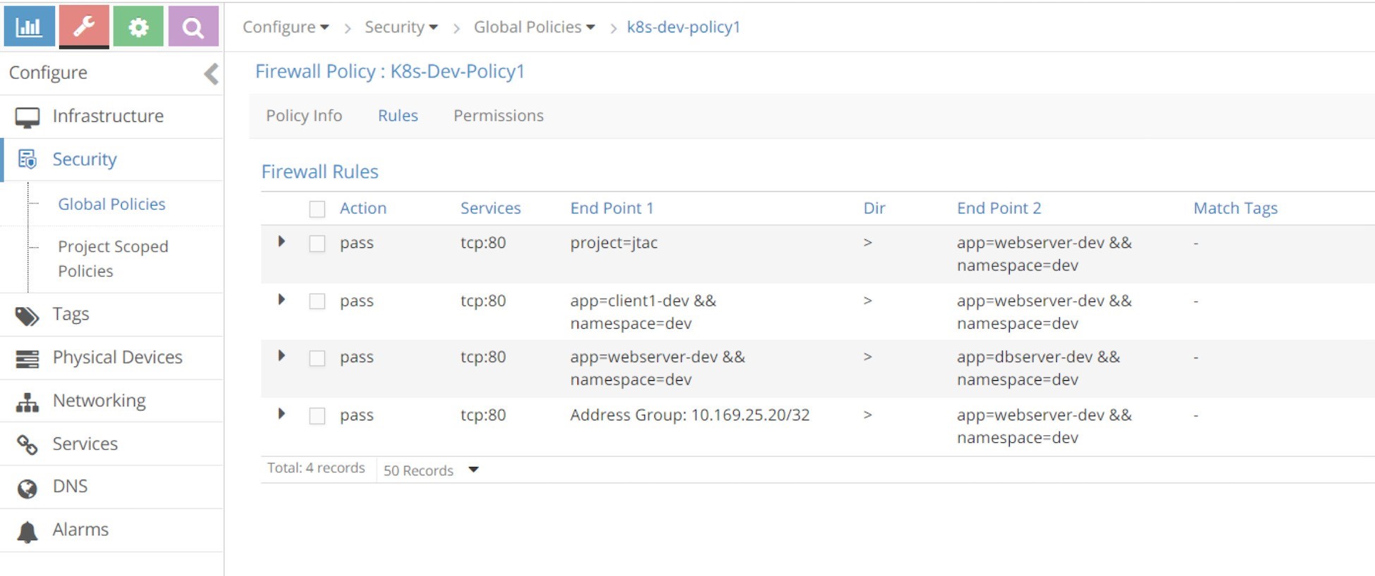
It looks similar to the Kubernetes network policy policy1 that we’ve tested. Let’s put the rules, displayed in the screen captures, into Table 3.
Table 3: Rules
Rule# | Action | Services | End Point1 | Dir | End Point2 | Match Tags |
1 | Pass | tcp:80 | project=jtac | > | app=webserver-dev && namespace=dev | - |
2 | Pass | tcp:80 | app=client1-dev && namespace=dev | > | app=webserver-dev && namespace=dev | - |
3 | Pass | tcp:80 | app=webserver-dev && namespace=dev | > | app=dbserver-dev && namespace=dev | - |
4 | Pass | tcp:80 | Address Group: 10.169.25.20/32 | > | app=webserver-dev && namespace=dev | - |
The first column of Table 8.2 is the rule number that we added; all other columns are imported from the UI screenshot. Now let’s compare it with the Kubernetes object information:
$ kubectl get netpol --all-namespaces -o yaml apiVersion: v1
items:
- apiVersion: extensions/v1beta1 kind: NetworkPolicy
metadata:
......
spec:
egress:
-	ports:
-	port: 80 protocol: TCP to:
-	podSelector:	#<---rule#3 matchLabels:
app: dbserver-dev ingress:
-	from:
-	ipBlock:	#<---rule#4 cidr: 10.169.25.20/32
-	namespaceSelector:	#<---rule#1 matchLabels:
project: jtac
-	podSelector:	#<---rule#2 matchLabels:
app: client1-dev ports:
-	port: 80 protocol: TCP
podSelector:
matchLabels:
app: webserver-dev policyTypes:
-	Ingress
-	Egress
The rules we see in firewall policy k8s-dev-policy1 match with rules in Kubernetes network policy policy1.
Rules in k8s-denyall Firewall Policy
Now let’s go back and examine the rules in the k8s-denyall policy that KM generated for our Kubernetes network policies.
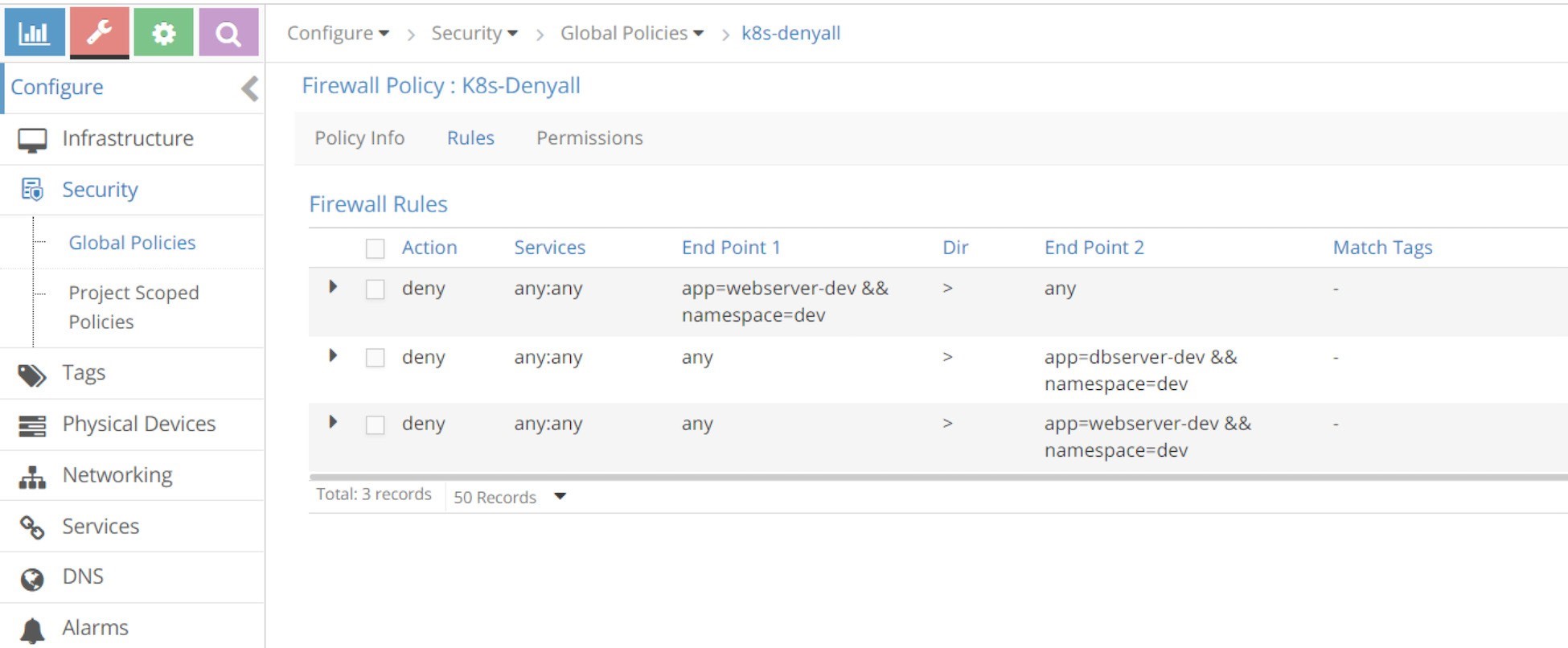
Again, if we convert that into a table it appears as shown in Table 4.
Table 4: Contrail UI: k8s-denyall Policy Rules
rule# | Action | Services | End Point1 | Dir | End Point2 | Match Tags |
1 | deny | any:any | app=webserver-dev && namespace=dev | > | any | - |
2 | deny | any:any | any | > | app=dbserver-dev && namespace=dev | - |
3 | deny | any:any | any | > | app=webserver-dev && namespace=dev | - |
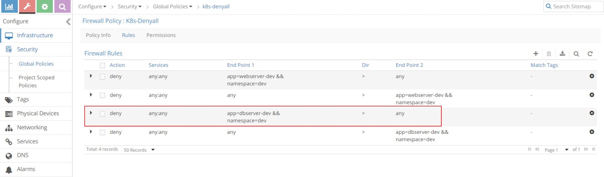
The k8s-alldeny rules are simple. They just tell Contrail to deny communication with all other pods that are not in the whitelist. One thing worth mentioning is that there is a rule in the direction from app=webserver-dev && namespace=dev to any, so that egress traffic is denied for webserver-dev pod, while there is no such a rule from app=dbserver-dev && namespace=dev to any. If you review our test in the last section, in the original policy policy2, we did not define an Egress option in policyTypes to deny egress traffic of dbserver-dev, that is why there is no such rule when translated into Contrail firewall, either. If we change policy2 to the new policy policy2-egress-denyall and examine the same, we’ll see the missing rule now.
Pay attention to the fact that the k8s-denyall policy only applies to those target pods – pods that are selected by the network policies. In this case it only applies to pods webserver-dev and dbserver-dev. Other pods like client-jtac or client-qa will not be effected. Instead, those pods will be applied by k8s-allowany policy, which we’ll examine next.
Rules in k8s-allowall Firewall Policy
In Figure 14, the k8s-allowall policy seems to have more rules than other policies.
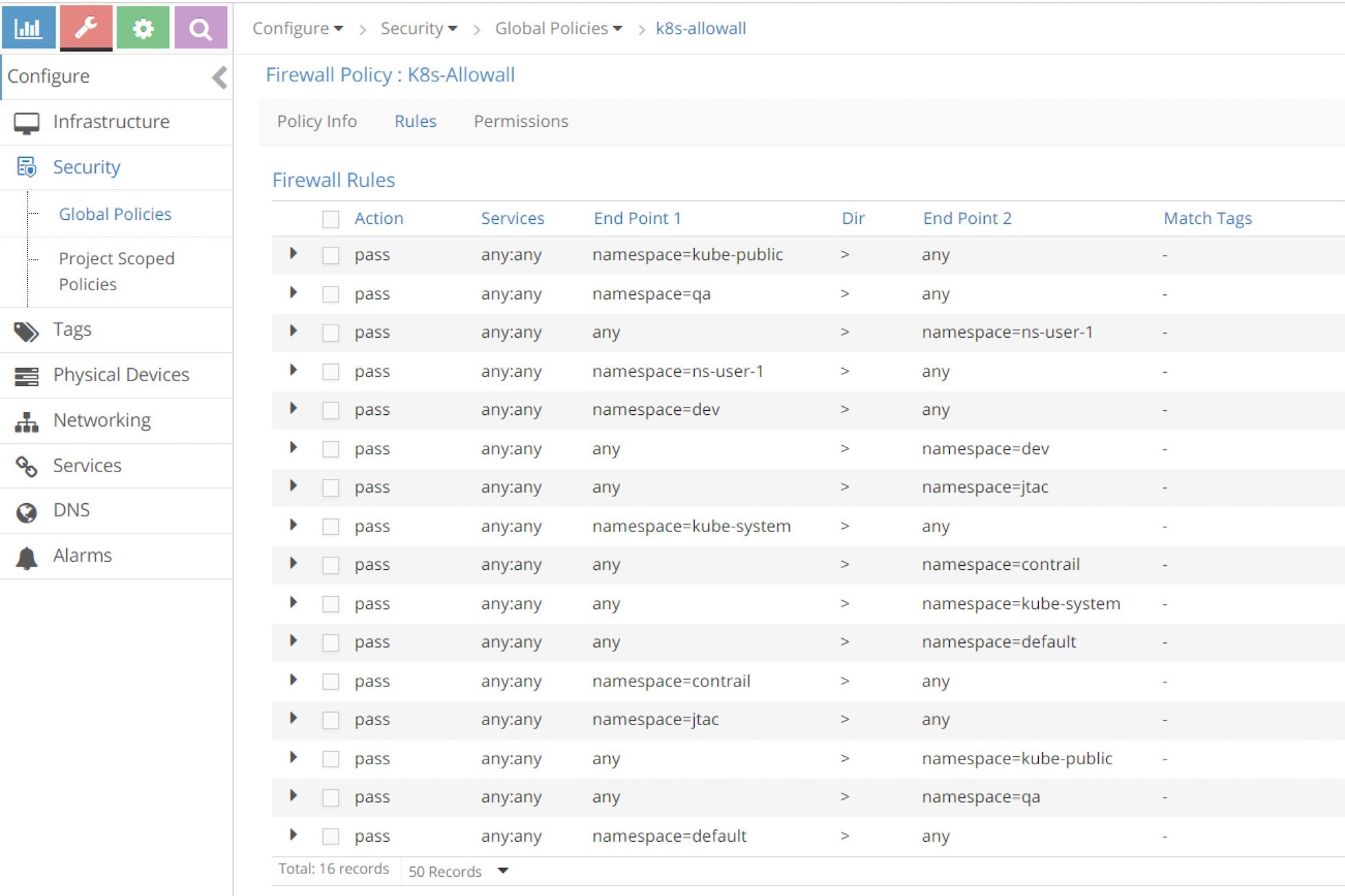
Despite the number of rules, in fact k8s-allowall is the simplest one. It works at the NS level and simply has two rules for each NS. In the UI, within the search field, key in a namespace as the filter, for example, dev or qa, and you’ll see these results in Figure 15 and Figure 16.
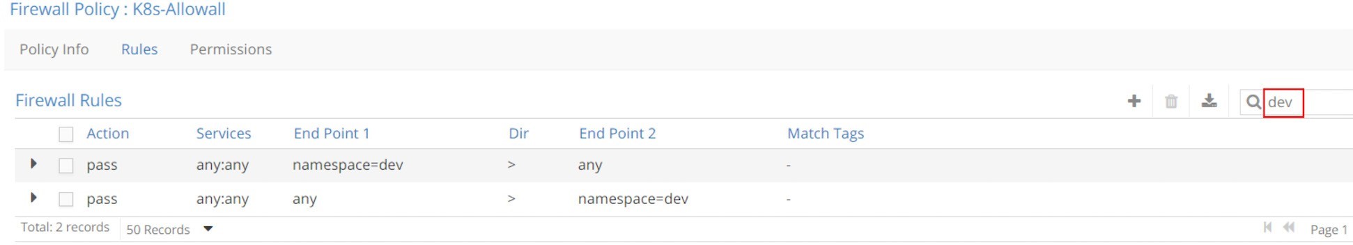
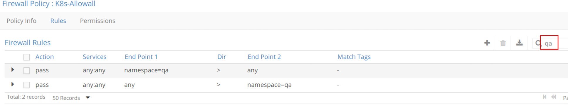
What this policy says is: for those pods that do not have any network policy applied yet, let’s continue the Kubernetes default allow-any-any networking model and allow everything!
Sequence Number
After having explored the Contrail firewall policy rules, let’s come back to the sequence number and see exactly how it works.
The sequence number is a number attached to all firewall policies and their rules that decides the order in which all policies are applied and evaluated, and does the same in one particular policy. The lower the sequence number the higher the priority. To find the sequence number you have to look into the firewall policy and policy rule object attributes in Contrail configuration database.
First let’s explore the firewall policy object in APS to check their sequence number.
In Chapter 5 we used the curl command to pull the loadbalancer object data when we introduced service. Here we used Config Editor to do the same.
Figure 17 and Figure 18 capture the sequence number in firewall policies.
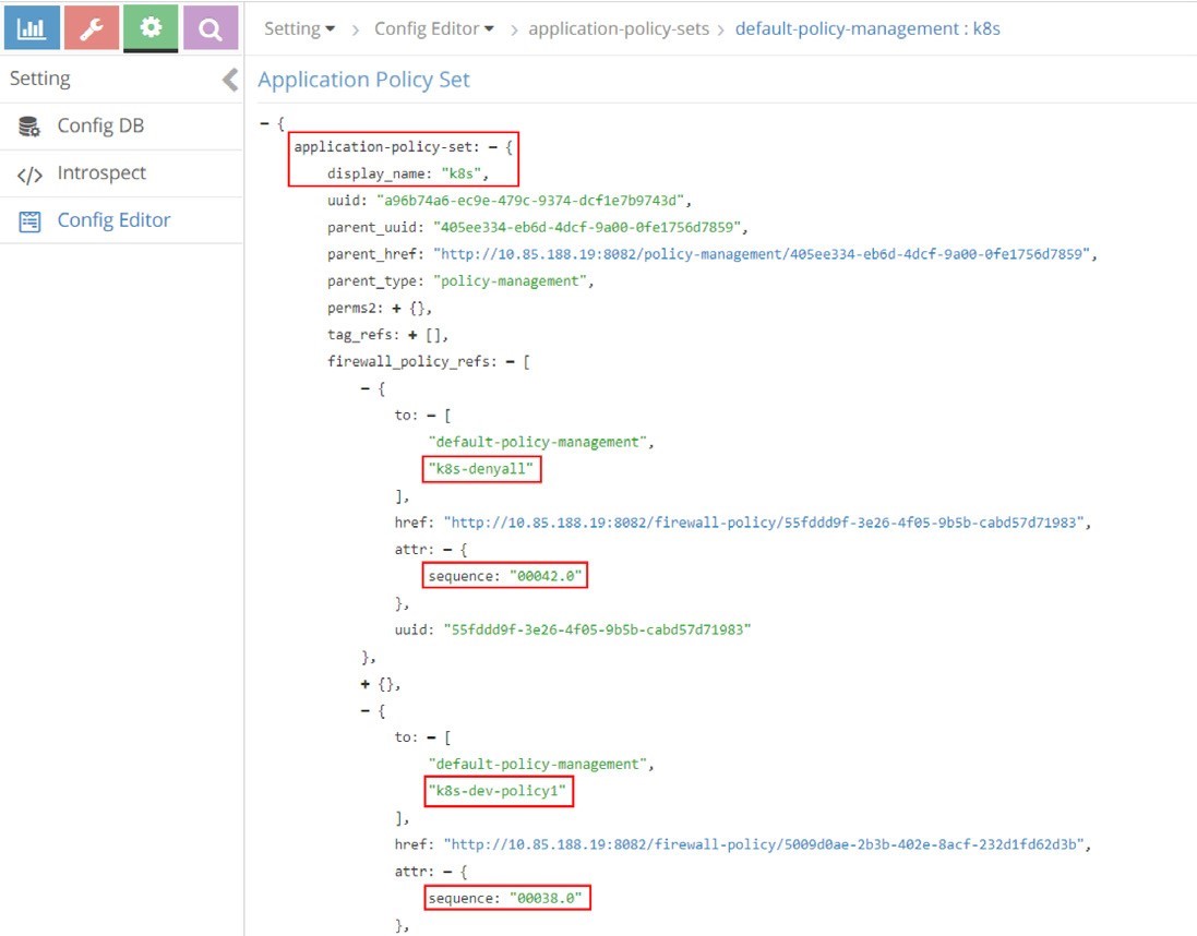
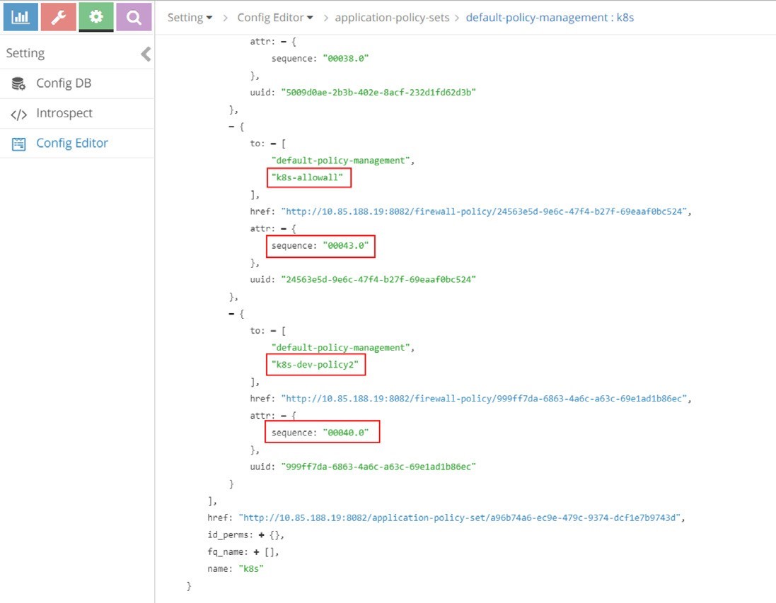
All five policies that we’ve seen appear in these screenshots, under APS k8s. For example, the policy k8s-dev-policy1, which maps to the Kubernetes network policy policy1 that we explicitly defined, and the policy k8s-denyall, which is what the system automatically generated. The figures show k8s-dev-policy1 and k8s-denyall have sequence numbers of 00038.0 and 00042.0, respectively. Therefore k8s-dev-policy1 has a higher priority and it will be applied and evaluated first. That means the traffic types we defined in the whitelist will be allowed first, then all other traffic to or from the target pod will be denied. This is the exact goal that we wanted to achieve.
All sequence numbers for all firewall policies are listed in Table 5, from the highest priority to the lowest:
Table 5: Sequence Numbers
Sequence Number | Firewall Policy |
00002.0 | k8s-Ingress |
00038.0 | k8s-dev-policy1 |
00040.0 | k8s-dev-policy2 |
00042.0 | k8s-denyall |
00043.0 | k8s-allowall |
Based on the sequence number, the application and evaluation order are the first explicit policies, followed by the deny all policy and ending with the allow all policy. The same order as in Kubernetes is honored.
Sequence Number in Firewall Policy Rules
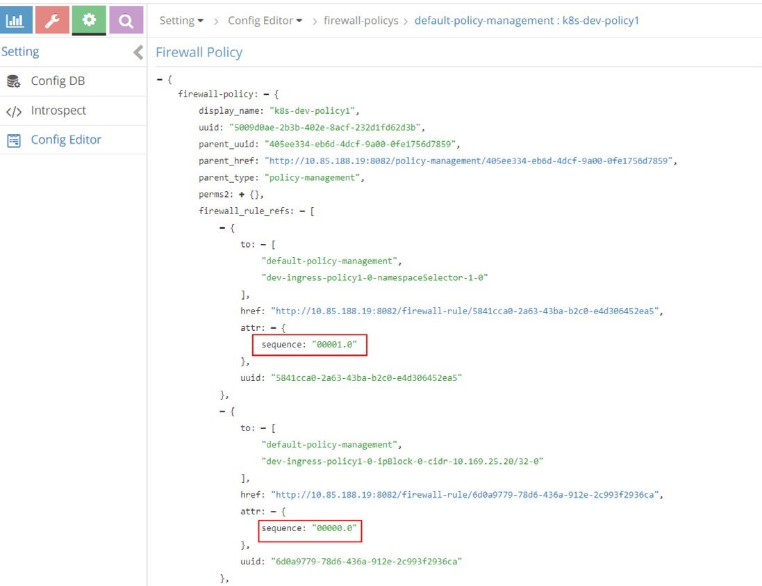
As mentioned previously, in the same firewall policy, policy rules will also have to be applied and evaluated in a certain order. In Contrail firewall that is again ensured by the sequence number. The sequence numbers in the rules of firewall policy k8s-dev-policy1 are displayed in Figure 19 and Figure 20.
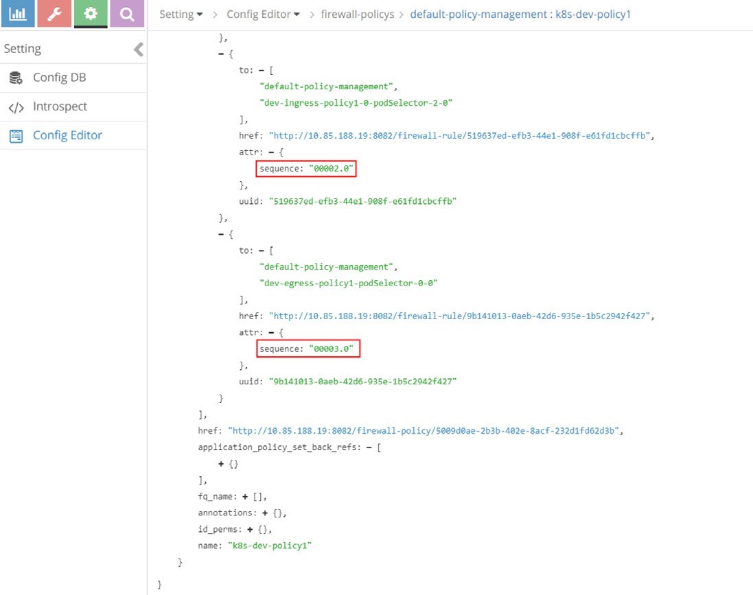
And Table 6 lists the sequence number of all rules of the firewall policy k8s-dev-policy1, from highest priority to the lowest.
Table 6: Sequence Numbers for Policy1
seq# | firewall rule |
00000.0 | dev-ingress-policy1-0-ipBlock-0-cidr-10.169.25.20/32-0 |
00001.0 | dev-ingress-policy1-0-namespaceSelector-1-0 |
00002.0 | dev-ingress-policy1-0-podSelector-2-0 |
00003.0 | dev-egress-policy1-podSelector-0-0 |
Let’s compare with our network policy YAML file configuration:
ingress:
-	from:
-	ipBlock:
cidr: 10.169.25.20/32	#<---seq# 00000.0
-	namespaceSelector:	#<---seq# 00001.0 matchLabels:
project: jtac
-	podSelector:	#<---seq# 00002.0 matchLabels:
app: client1-dev


ports:
-	protocol: TCP port: 80
egress:
-	to:
-	podSelector:	#<---seq# 00003.0 matchLabels:
app: dbserver-dev ports:
-	protocol: TCP port: 80
We find that the rules sequence number is consistent with the sequence that appears in the YAML file. In other words, rules will be applied and evaluated in the same order as they are defined.
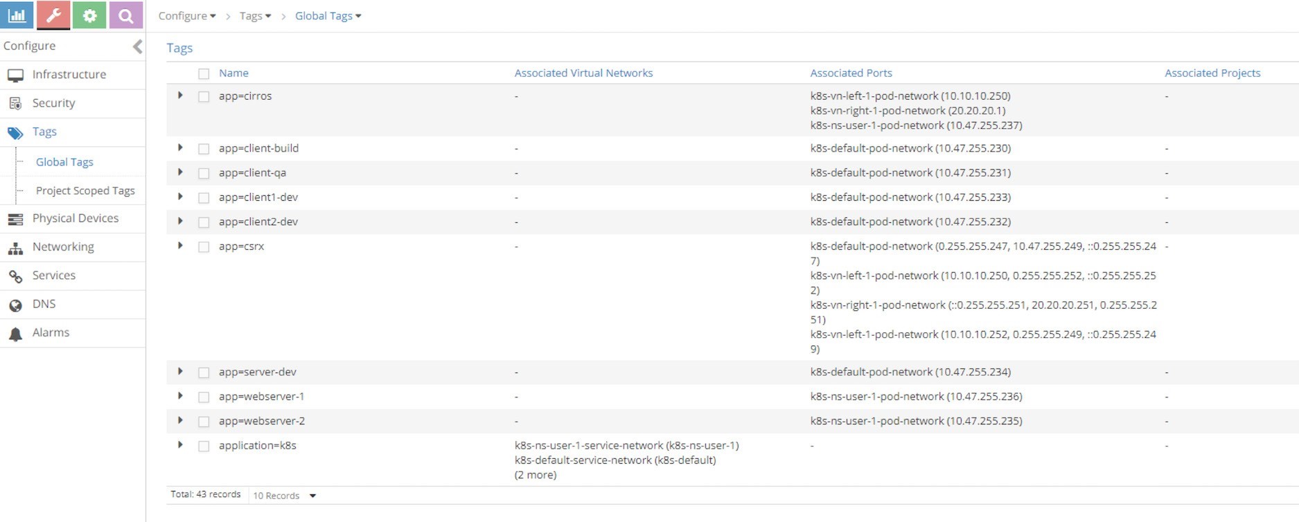
Tag
We’ve been talking about the Contrail tags and we already know that contrail-kube-manager will translate each Kubernetes label into a Contrail tag, which is attached to the respective port of a pod as shown in Figure 21.
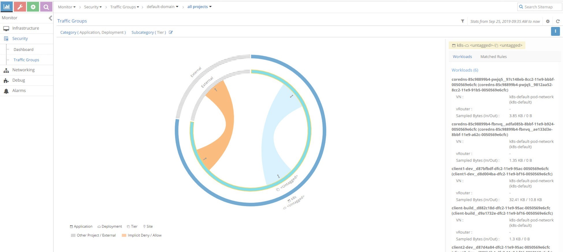
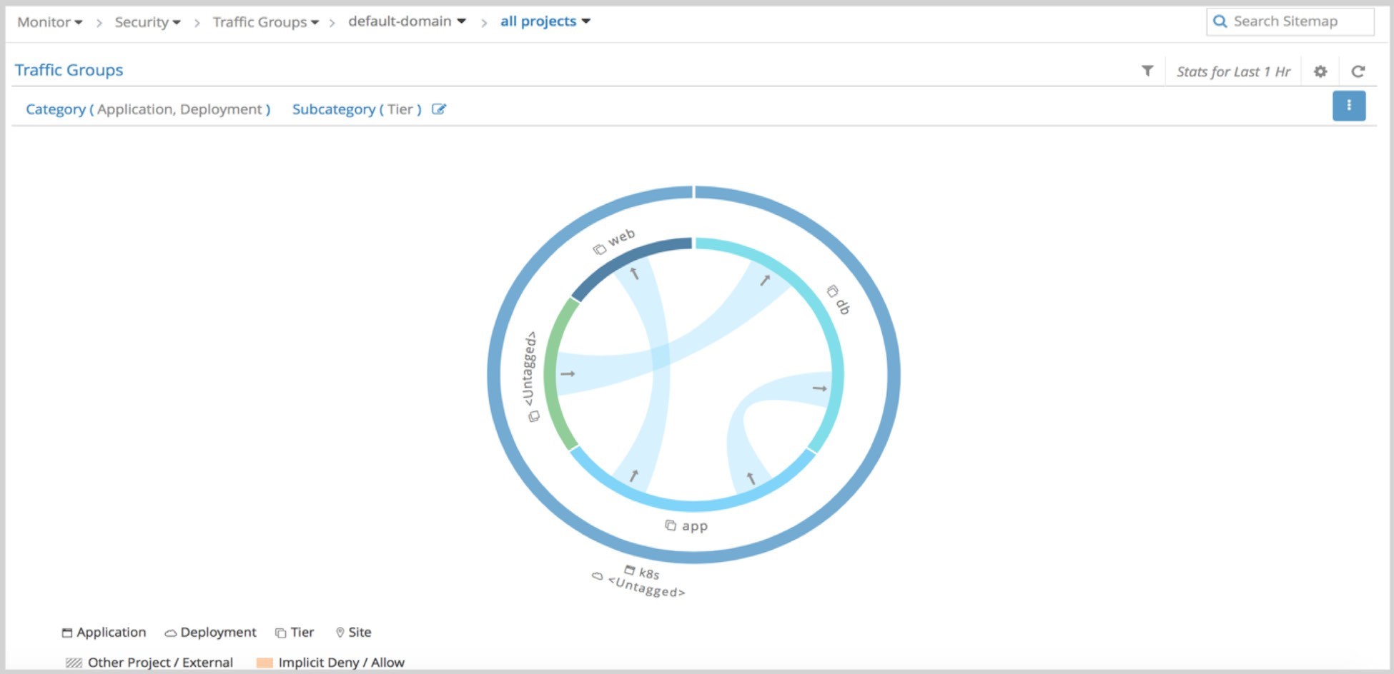
UI Visualization
Contrail UI provides a nice visualization for security as shown in Figure 22. It’s self - explanatory if you know how Contrail security works.