Contrail Ingress
Chapter 3 contained ingress basics, the relation to service, ingress types, and the YAML file of each type.
This chapter introduces the details of ingress workflow in Contrail implementation, then uses a few test cases to demonstrate and verify ingress in the Contrail environment.
Contrail Ingress Load Balancer
Like Contrail’s service implementation, Contrail Ingress is also implemented through load balancer, but with a different loadbalancer_provider attribute. Accordingly, the contrail-svc-monitor component takes different actions to implement Ingress in Contrail environments.
Remember that way back in the Contrail/Kubernetes architecture section we gave the object mapping between Kubernetes and Contrail, and that Kubernetes service maps to ECMP load balancer (native) and Ingress maps to Haproxy load balancer.
In the service section when we were exploring the load balancer and the relevant objects (listener, pool, and member), we noticed the load balancer’s loadbalancer_provider type is native.
"loadbalancer_provider": "native",
In this section we’ll see the loadbalancer_provider type is opencontrail for ingress’s load balancer. We’ll also look into the similarities and differences between service load balancer and Ingress load balancer.
Contrail Ingress Workflow
When an Ingress is configured in a Contrail Kubernetes environment, the event will be noticed by other system components and a lot of actions will be triggered. The deep level implementation is beyond the scope of this book, but at a high level this is the workflow:
The contrail-kube-manager keeps listening to the events of the kube-apiserver.
User creates an ingress object (rules).
The contrail-kube-manager gets the event from kube-apiserver.
The contrail-kube-manager creates a load balancer object in contrail DB, and sets the load balancer_ provider type as open contrail for ingress (where as it is native for service).
As mentioned earlier, the contrail-service-monitor component sees the load balancer creation event, based on the load balancer_provider type, and it invokes the registered load balancer driver for the specified load balancer_provider type:
If the load balancer_provider type is native, it will invoke the ECMP loadbalancer driver for ECMP load balancing, which we reviewed in the previous section.
If the load balancer_provider type is open contrail, it will invoke the haproxy load balancer driver, which triggers the haproxy processes to be launched in Kubernetes nodes.
As you can see, Contrail implements Ingress with haproxy load balancer, as you also read in the section on Contrail Kubernetes object mapping. Chapter 3 described the ingress controller, and how multiple ingress controllers can coexist in Contrail. In the Contrail environment, the contrail-kube-manager plays the Ingress controller role. It reads the ingress rules that users input, and programs them into the load balancer. Furthermore:
For each Ingress object, one load balancer will be created;
Two haproxy processes will be created for Ingress and they are working in active-standby mode:
one compute node runs the active haproxy process
the other compute node runs the standby haproxy process
Both haproxy processes are programmed with appropriate configuration, based on the rules defined in the Ingress object.
Contrail Ingress Traffic Flow
Client requests, such as a type of overlay traffic, may come from two different sources, depending on who initiates the request:
An internal request: requests coming from another pod inside of the cluster.
An external request: requests coming from an Internet host outside of the cluster.
The only difference between the two is how the traffic hits the active haproxy. An ingress will be allocated two IPs: a cluster-internal virtual IP and an external virtual IP.
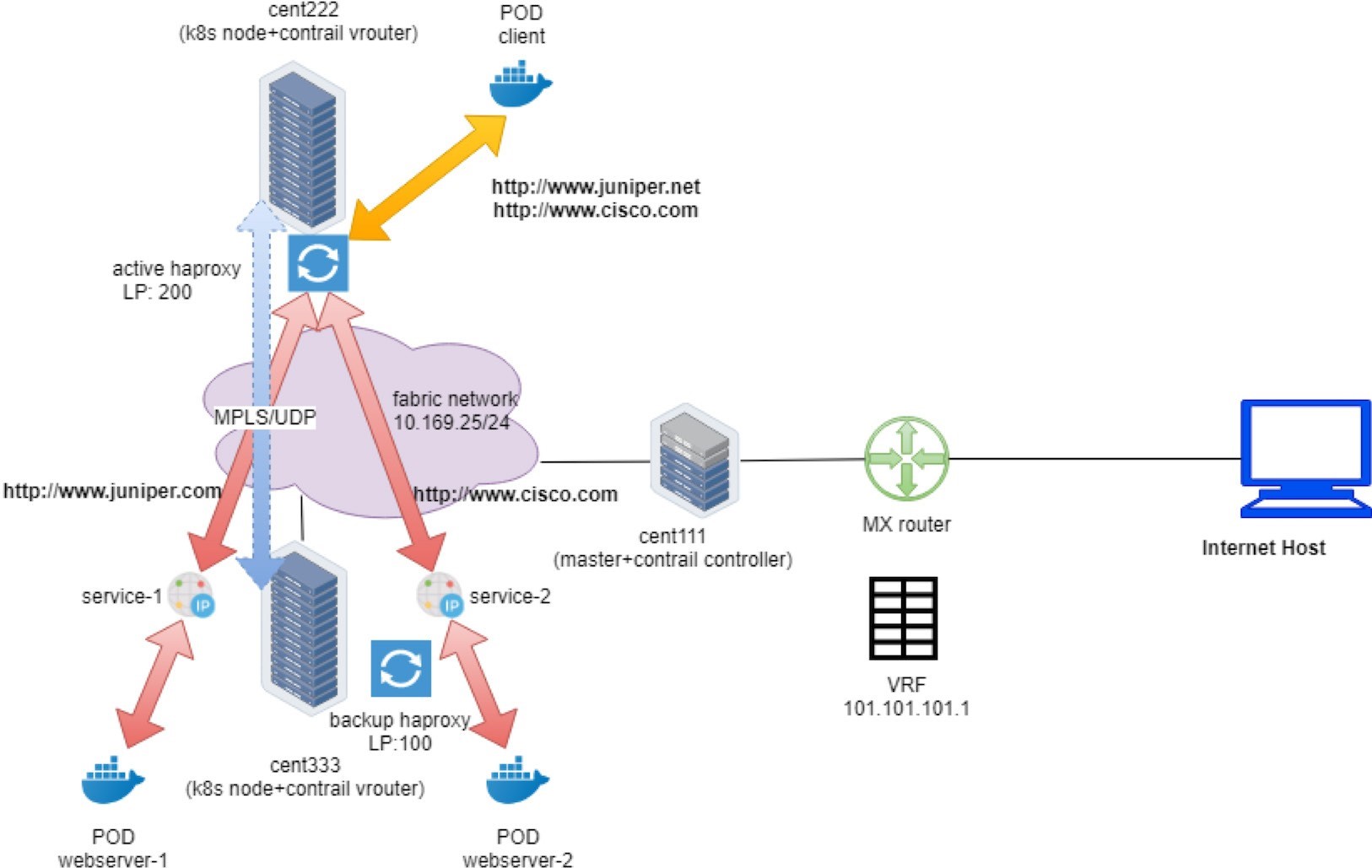
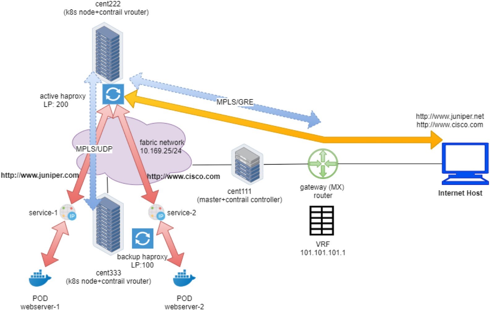
Here is the traffic flow for the client request:
- For internal requests, it hits Ingress’s internal VIP directly.
- For external requests, it first hits Ingress’s external VIP – the floating IP, which is the one exposed to external, and that’s when NAT starts to play as we’ve explained in the FIP section. After NAT processing, traffic is forwarded to the internal Ingress VIP.
- From this moment on, both types of requests are processed exactly the same way.
- The requests will be proxied to the corresponding service IP.
- Based on the availability of the backend pods, it will be sent to the node where one of the backend pods are located and eventually reaches the target pods.
- In case the backend pods are running in a different compute node than the one running active haproxy, a MPLS over UDP tunnel is created between the two compute nodes.
Figure 1 and Figure 2 illustrate the end-to-end service request flow when accessing from a pod in the cluster and when accessing from an Internet host.
Contrail supports all three types of ingress:
HTTP-based single-service ingress
simple-fanout ingress
name-based virtual hosting
ingress Next we’ll look into each type of ingress
Ingress Setup
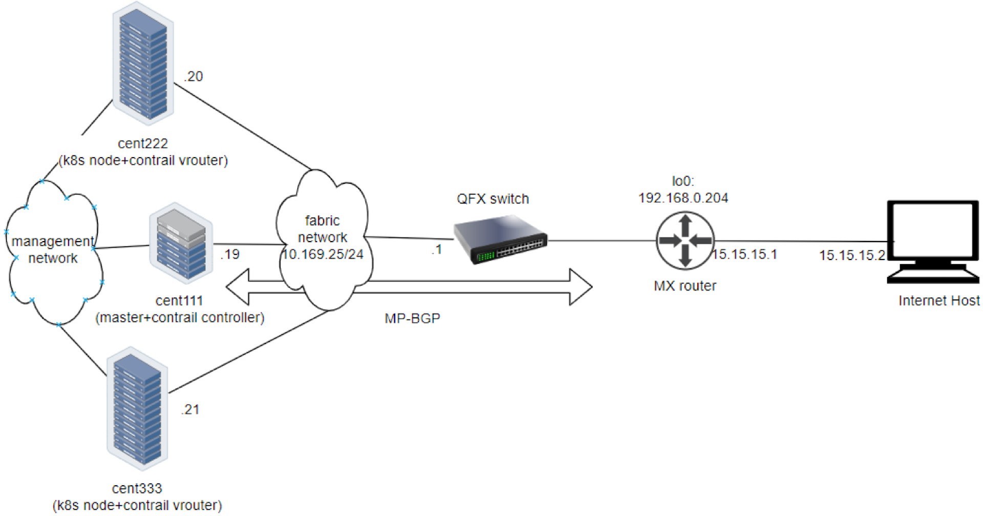
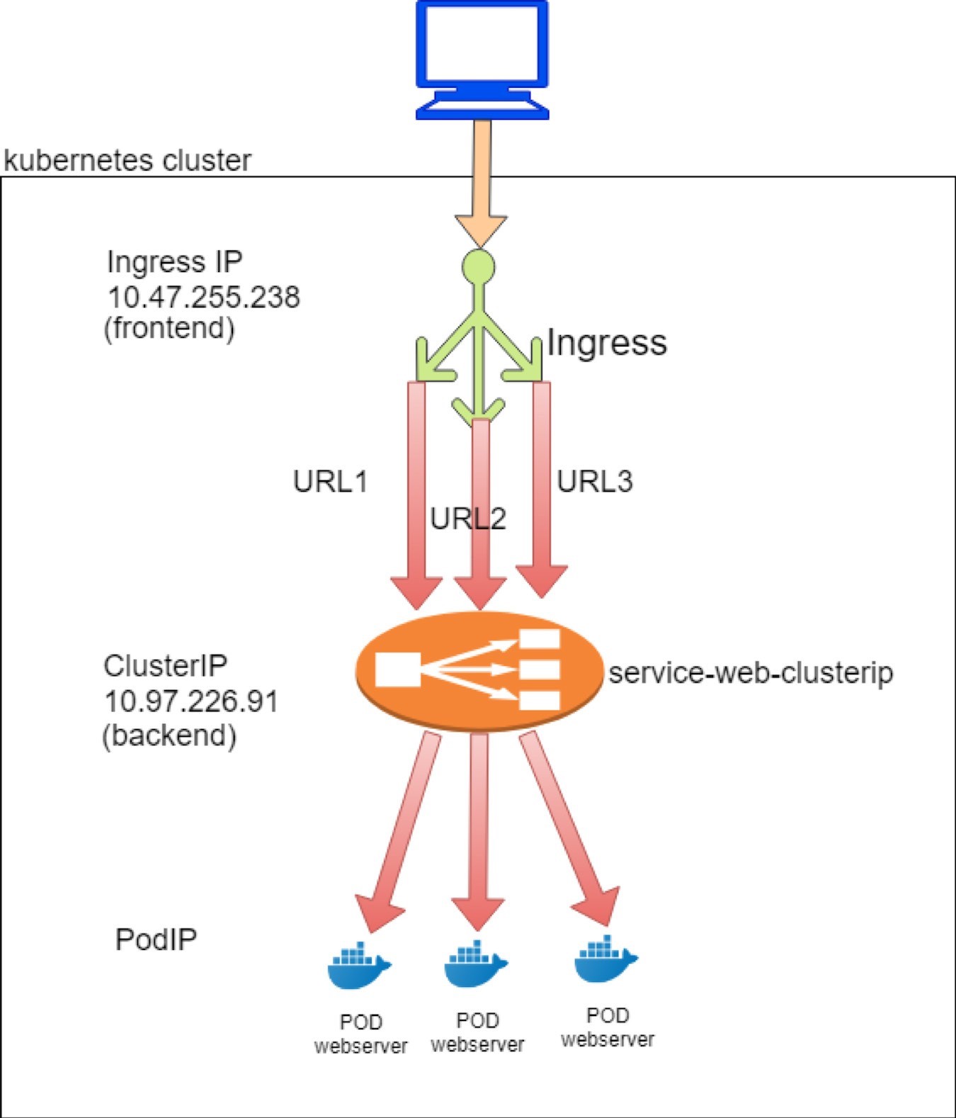
This book’s lab uses the same testbed as used for the service test, shown in Figure 3.
Single Service Ingress
Single service ingress is the most basic form of ingress. It does not define any rules and its main use is to expose service to the outside world. It proxies all incoming service requests to the same single backend service:
To demonstrate single service type of ingress, the objects that we need to create are:
an Ingress object that defines the backend service
a backend service object
at least one backend pod for the service
Ingress Definition
In the single service ingress test lab, we want to request that any URLs are directed to service-web-clusterip with servicePort 8888. Here is the corresponding YAML definition file:
This does not look fancy. Basically there is nothing else but a reference to a single service webserver-1 as its backend. All HTTP requests will be dispatched to this service, and from there the request will reach a backend pod. Simple enough. Let’s look at the backend service.
Backend Service Definition
You can use the exact same service as introduced in the service example:
The service type is optional. With Ingress, service does not need to be exposed externally anymore. Therefore, the LoadBalancer type of service is not required.
Backend Pod Definition
Just as in the service example, you can use exactly the same webserver deployment to launch backend pods:
All in One YAML File
As usual, you can create an individual YAML file for each of the objects, but considering that these objects always need to be created and removed together in Ingress, it’s better to merge definitions of all these objects into one YAML file. YAML syntax supports this by using document delimiters (a --- line between each object definition):
The benefits of the all-in-one YAML file are:
You can create/update all objects in the YAML file in one go, using just one kubectl apply command.
Similarly, if anything goes wrong and you need to clean up, you can delete all objects created with the YAML file in one kubectl delete command.
Whenever needed, you can still delete each individual object independently, by providing the object name.
During test processing, you may need to create and delete all objects as a whole very often, so grouping multiple objects in one YAML file can be very convenient.
Deploy the Single Service Ingress
Before applying the YAML file to get all the objects created, let’s take a quick look at our two nodes. You want to see if there is any haproxy process running without ingress, so later, after you deploy ingress, you can compare:
So the answer is no, there is no haproxy process in either of the nodes. Haproxy will be created only after you create Ingress and the corresponding load balancer object is seen by the contrail-service-monitor. We’ll check this again after an Ingress is created:
The ingress, one service, and one deployment object have now been created.
Ingress Object
Let’s examine the ingress object:
$ kubectl get ingresses.extensions -o wide
				NAME	HOSTS  ADDRESS
						PORTS AGE ingress-ss   *
						10.47.255.238,101.101.101.
				1   80	29m

$ kubectl get
ingresses.extensions -o
yaml apiVersion: v1
items:
- apiVersion:
extensions/v1beta1
kind: Ingress
metadata:
annotations:
kubectl.kubernetes.io/last-applied-configuration: |
{"apiVersion":"extensions/v1beta1",
 "kind":"Ingress",
"metadata":{"annotations":{},"name":"ingress-
ss","namespace":"ns-user-1"},
"spec":{"backend":{"serviceName":"service
-web-clusterip ", "servicePort":80}}}
creationTimestamp:
2019-07-18T04:06:29Z
generation: 1
name: ingress-ss
namespace: ns-user-1
resourceVersion: "845969"
selfLink: /apis/extensions/v1beta1/namespaces/ns-
user-1/ingresses/ingress-ss uid: 6b48bd8f-
a911-11e9-8112-0050569e6cfc
spec:
backend:
serviceName: service-web-clusterip
servicePort: 80
status:
		loadBalancer:
		ingress:
		- ip: 101.101.101.1
		- ip: 10.47.255.238
kind:
 List metadata:
resourceVersion:
 "" selfLink: ""
As expected, the backend service is properly applied to the ingress. In this single-service ingress there are no explicit rules defined to map a certain URL to a different service – all HTTP requests will be dispatched to the same backend service.
In the items metadata annotations kubectl.kubernetes.io/last-applied-configuration section of the output…
…Actually contains the configuration information that you provided. You can format it (with a JSON formatting tool like Python’s json.tool module) to get a better view…
{
"apiVersion": "extensions/v1beta1",
"kind": "Ingress",
"metadata":
 {
	"annotations": {},
	"name": "ingress-ss",
	"namespace": "ns-user-1"
},
"spec": {
"backend": {
"serviceName": "service-web-clusterip",
	"servicePort": 80
		}
	 }
}
…And you can do the same formatting for all other objects to make it more readable.
But what may confuse you are the two IP addresses shown here:loadBalancer: ingress: - ip: 101.101.101.1 - ip: 10.47.255.238
We’ve seen these two subnets in service examples:
10.47.255.x is a cluster-internal podIP allocated from the pod’s default subnet, and
101.101.101.x is the public FIP associated with an internal IP. The question is: Why does ingress even require a podIP and FIP?
Let’s hold off on the answer for now and continue to check the service and pod object created from the all-in-one YAML file. We’ll come back to this question shortly.
Service Objects
Let’s check on
services:
$ kubectl get svc -o wide NAME TYPE CLUSTER-IP EXTERNAL-IP PORT(S) AGE SELECTOR service-web-clusterip ClusterIP 10.97.226.91 <none> 8888/TCP 28m app=webserver
The service is created and allocated a clusterIP. We’ve seen this before and it looks like nothing special. Now, let’s look at the backend and client pods:
$ kubectl get pod -o wide --show-labels NAME READY STATUS ... IP NODE ... LABELS client 1/1 Running ... 10.47.255.237 cent222 ... app=client webserver-846c9ccb8b-9nfdx 1/1 Running ... 10.47.255.236 cent333 ... app=webserver
Everything looks fine, here. There is a backend pod running for the service. You have already learned how selector and label works in service-pod associations. Nothing new here. So let’s examine the haproxy and try to make some sense out of the two IPs allocated to the ingress object.
Haproxy Processes
Earlier, before the ingress was created, we were looking for the haproxy process in nodes but could not see anything. Let’s check it again and see if any magic happens:
On node cent222:
$ ps aux | grep haproxy 188 23465 0.0 0.0 55440 852 ? Ss 00:58 0:00 haproxy -f /var/lib/contrail/loadbalancer/haproxy/5be035d8-a918-11e9-8112- 0050569e6cfc/haproxy.conf -p /var/lib/contrail/loadbalancer/haproxy/5be035d8-a918-11e9-8112-0050569e6cfc/haproxy.pid -sf 23447
On node cent333:
$ ps aux | grep haproxy 188 16335 0.0 0.0 55440 2892 ? Ss 00:58 0:00 haproxy -f /var/lib/contrail/loadbalancer/haproxy/5be035d8-a918-11e9-8112- 0050569e6cfc/haproxy.conf -p /var/lib/contrail/loadbalancer/haproxy/5be035d8-a918-11e9-8112-0050569e6cfc/haproxy.pid -sf 16317
And right after ingress is created, you can see a haproxy process created in each of our two nodes! Previously we stated that Contrail Ingress is also implemented through load balancer (just like service). Since ingress’s loadbalancer_provider type is opencontrail, ‘contrail-svc-monitor invokes the haproxy load balancer driver. The haproxy driver generates the required haproxy configuration for the ingress rules and triggers haproxy processes to be launched (in active-standby mode) with the generated configuration in Kubernetes nodes.
Ingress Load Balancer Objects
We’ve mentioned the ingress load balancer a few times but haven’t looked at it yet. In the service section, we’ve looked into the service load balancer object in the UI, and we inspected some details about the object data structure. Now, after creating the ingress object, let’s check the list of load balancer objects again and see what ingress brings in here starting with the UI at Configure>Load Balancers.
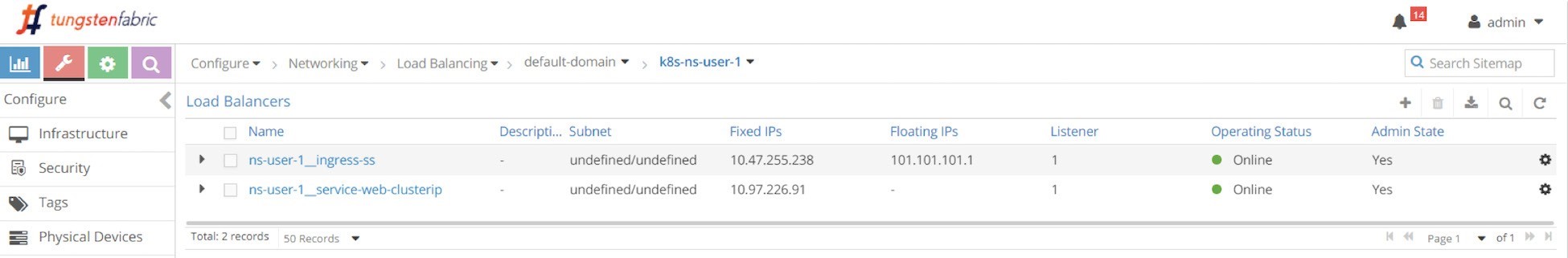
Two load balancers are generated after applying the all-in-one YAML file:
Load balancer ns-user-1 ingress-ss for ingress ingress-ss
Load balancer ns-user-1 webservice-clusterip for service webserver-clusterip
We’ve been through the service load balancer object previously, and if you expand the service you will see lots of detail but nothing should surprise you.
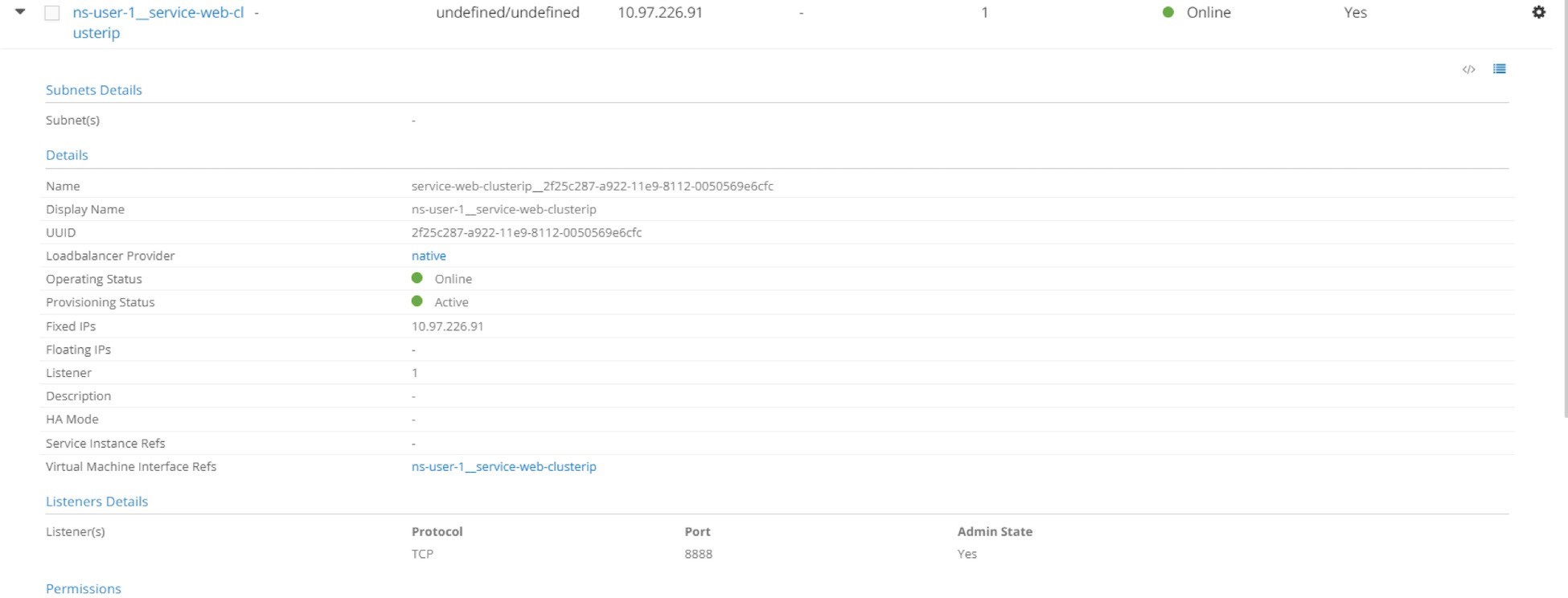
As you can see, the service load balancer has a clusterIP and a listener object that is listening on port 8888. One thing to highlight is the loadbalancer_provider. This type is native, so the action contrail-svc-monitor takes is the Layer 4 (Application Layer) ECMP process, which is explored extensively in the service section. Let’s expand the ingress load balancer and glance at the details.
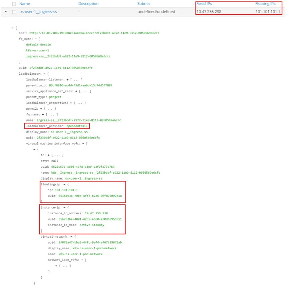
The highlights in Figure 6 are:
The loadbalancer_provider is opencontrail
The ingress load balancer has a reference to a virtual-machine-interface (VMI) object
And the VMI object is referred to by an instance-ip object with a (fixed) IP 10.47.255.238 and a floating-ip object with a (floating) IP 101.101.101.1.
And you can explain the ingress IP 10.47.255.238 seen in the ingress as:
It is a cluster-internal IP address allocated from the default pod network as a load balancer VIP
It is the frontend IP that the ingress load balancer will listen to for HTTP requests
And it is also what the public floating IP 101.101.101.1 maps to with NAT.
This book refers to this private IP by different names that are used interchangeably, namely: ingress internal IP, ingress internal VIP, ingress private IP, ingress load balancer interface IP, etc., to differentiate it from the ingress public floating IP. You can also name it as ingress pod IP since the internal VIP is allocated from the pod network. Similarly, it refers to the ingress public floating IP as ingress external IP.
Now to compare the different purposes of these two IPs:
Ingress pod IP is the VIP facing other pods inside of a cluster. To reach ingress from inside of the cluster, requests coming from other pods will have their destination IP set to Ingress podIP.
Ingress floating IP is the VIP facing the Internet host outside world. To reach ingress from outside of the cluster, requests coming from Internet hosts need to have their destinations IP set to Ingress FIP. When the node receives traffic destined to the ingress floating IP from outside of the cluster, the vRouter will translate it into the Ingress podIP.
The detailed ingress load balancer object implementation refers to a service instance, and the service instance includes other data structures or references to other objects (VMs, VMIs, etc.). Overall it is more complicated and involves more details than what’s been covered in this book. We’ve tailored some of the details into a high-level overview so that important concepts like haproxy and the two ingress IPs can at least be understood.
Once an HTTP/HTTPS request arrives at the ingress podIP, internally or externally, the ingress load balancer will do HTTP/HTTPS proxy operations through the haproxy process, and dispatch the requests towards the service and eventually to the backend pod.
We’ve seen that the haproxy process is running, to examine more details of this proxy operation, let’s check its configuration file for details on the running parameters.
Haproxy.conf File
In each (compute) node, under the /var/lib/contrail/Loadbalancer/haproxy/
folder there will be a subfolder for each load balancer UUID. The
file structure looks like this:8fd3e8ea-9539-11e9-9e54-0050569e6cfc ━━━ haproxy.conf ━━━ haproxy.pid ━━━ haproxy.sock
You can check the haproxy.conf file for the haproxy configuration:
The configuration is simple, and Figure 6.7 illustrates it. The highlights of Figure 6.7 are:
The haproxy frontend represents the frontend of an ingress, facing clients.
The haproxy backend represents the backend of an ingress, facing services.
The haproxy frontend defines a bind to the ingress podIP and mode http. These knobs indicate what the frontend is listening to.
The haproxy backend section defines the server, which is a backend service in our case. It has a format of serviceIP:servicePort, which is the exact service object we’ve created using the all-in-one YAML file.
The default_backend in the frontend section defines which backend is the default: it will be used when a haproxy receives a URL request that has no explicit match anywhere else in the frontend section. In this case the default_backend refers to only the backend service 10.97.226.91:8888 This is due to the fact that there are no rules defined in single service Ingress, so all HTTP requests will go to the same default_backend service, regardless of what URL the client sent.
Later, in the simple fanout Ingress and name-based virtual hosting Ingress examples, you will see another type of configuration statement use_backend…if… that can be used to force each URL to go to a different backend.
Throughout this configuration, the haproxy implemented our single service ingress.
Gateway Router VRF Table
We’ve explored a lot inside of the cluster, so now let’s look at the gateway router’s VRF table:
Same as in the service example, from outside of the cluster, only floating IP is visible. Running the detailed version of the show command conveys more information:
The show detail reveals:
The vRouter advertises the floating IP prefix to Contrail Controller through XMPP. At least two pieces of information from the output indicate who represents the floating IP in this example - node cent222:
The Protocol next hop being 10.169.25.20
The Route Distinguisher being 10.169.25.20:5
And through MP-BGP, Contrail Controller reflects the floating IP prefix to the gateway router. Source: 10.169.25.19 indicates this fact.
So, it looks like cent222 is selected to be the active haproxy node and the other node, cent333, is the standby one. Therefore you should expect a client request coming from the Internet host to go to node cent222 first. Of course, the overlay traffic will be carried in MPLS over the GRE tunnel, same as what you’ve seen from the service example.
The floating IP advertisement towards the gateway router is exactly the same in all types of ingresses.
Another fact that we’ve somewhat skipped on purpose is the different local preference value used by the active and standby node when advertising the floating IP prefix. A complete examination involves other complex topics, like the active node selection algorithm, and so on, but it is worth it to understand this from a high level.
Both nodes have load balancer and haproxy running, so both will advertise the floating IP prefix 101.101.101.1 to the gateway router. However, they are advertised with different local preference values. The active node will advertise with a value of 200 and the standby node with 100. Contrail Controller both have routes from the two nodes, but only the winning one will be advertised to the gateway router. That is why the other BGP route is dropped and only one is displayed. Localpref being 200 proves it is coming from the active compute node. This applies to both the ingress public floating IP route and the internal VIP route advertisement.
Ingress Verification: Internal
After exploring a lot about ingress load balancer and the related service, pod objects, etc., it’s time to verify the end-to-end test result. Since the Ingress serves both inside and outside of the cluster, our verification will start from the client pod inside of the cluster and then from an Internet host outside of it. First, from the inside of cluster:
$ kubectl exec -it client-- \ curl -H 'Host:www.juniper.net' 10.47.255.238 | w3m -T text/html | cat Hello This page is served by a Contrail pod IP address = 10.47.255.236 Hostname = webserver-846c9ccb8b-9nfdx
$ kubectl exec -it client-- \ curl -H ''Host:www.cisco.com' ' 10.47.255.238 | w3m -T text/html | cat Hello This page is served by a Contrail pod IP address = 10.47.255.236 Hostname = webserver-846c9ccb8b-9nfdx
$ kubectl exec -it client-- \ curl -H ''Host:www.google.com' ' 10.47.255.238 | w3m -T text/html | cat Hello This page is served by a Contrail pod IP address = 10.47.255.236 Hostname = webserver-846c9ccb8b-9nfdx
$ kubectl exec -it client -- \ curl 10.47.255.238:80 | w3m -T text/html | cat Hello This page is served by a Contrail pod IP address = 10.47.255.236 Hostname = webserver-846c9ccb8b-9nfdx
You still use the curl command to trigger HTTP requests towards the ingress’s private IP. The return proves our Ingress works: requests towards different URLs are all proxied to the same backend pods, through the default backend service, service-web-clusterip.
In the fourth request we didn’t give a URL via -H, so curl will fill host with the request IP address, 10.47.255.238 in this test, and again it goes to the same backend pod and gets the same returned response.
The -H option is important in ingress tests with curl. It carries the full URL in HTTP payloads that the ingress load balancer is waiting for. Without it the HTTP header will carry Host: 10.47.255.238, which has no matching rule, so it will be treated the same as with an unknown URL.
Ingress Verification: External (Internet host)
The more exciting part of the test is to externally visit the URLs. Overall, we’re hoping ingress meant to expose services to the Internet host, even though it does not have to. To make sure the URL resolves to the right floating IP address, you need to update the /etc/hosts file by adding one line at the end – you probably don’t want to just end up with a nice webpage from an official website as your test result:
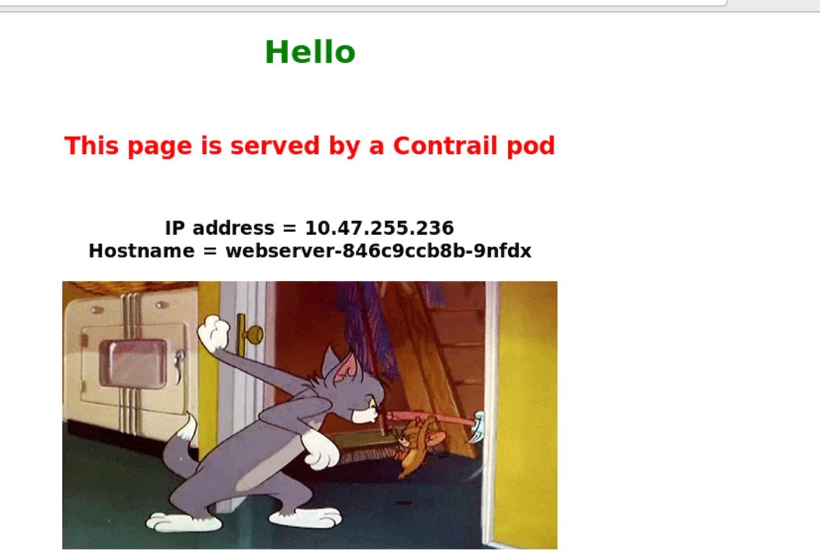
Now, from the Internet host’s desktop, launch your browser, and input one of the three URLs. By refreshing the pages you can confirm all HTTP requests are returned by the same backend pod, as shown in Figure 8.
The same result can also be seen from curl. The command is exactly the same as what we’ve been using when testing from a pod, except this time you send requests to the ingress external floating IP, instead of the ingress internal podIP. From the Internet host machine:
$ curl -H 'Host:www.juniper.net' 101.101.101.1 | w3m -T text/html | cat Hello This page is served by a Contrail pod IP address = 10.47.255.236 Hostname = webserver- 846c9ccb8b-9nfdx [giphy
$ curl -H 'Host:www.cisco.com' 101.101.101.1 | w3m -T text/html | cat Hello This page is served by a Contrail pod IP address = 10.47.255.236 Hostname = webserver- 846c9ccb8b-9nfdx [giphy
$ curl -H 'Host:www.google.com' 101.101.101.1 | w3m -T text/html | cat Hello This page is served by a Contrail pod IP address = 10.47.255.236 Hostname = webserver- 846c9ccb8b-9nfdx [giphy
$ curl 101.101.101.1 | w3m -T text/html | cat Hello This page is served by a Contrail pod IP address = 10.47.255.236 Hostname = webserver- 846c9ccb8b-9nfdx [giphy]
Everything works! Okay, next we’ll look at the second ingress type simple fanout Ingress. Before going forward, you can take advantage of the all-in-one YAML file and everything can be cleared with one kubectl delete command using the same all-in-one YAML file:
$ kubectl delete -f ingress/ingress-single- service.yaml ingress.extensions "ingress-ss" deleted service "service-web- clusterip" deleted deployment "webserver" deleted
Simple Fanout Ingress
Both the simple fanout Ingress and name-based virtual host Ingress support URL routing, the only difference is that the former is based on path and the latter is based on host.
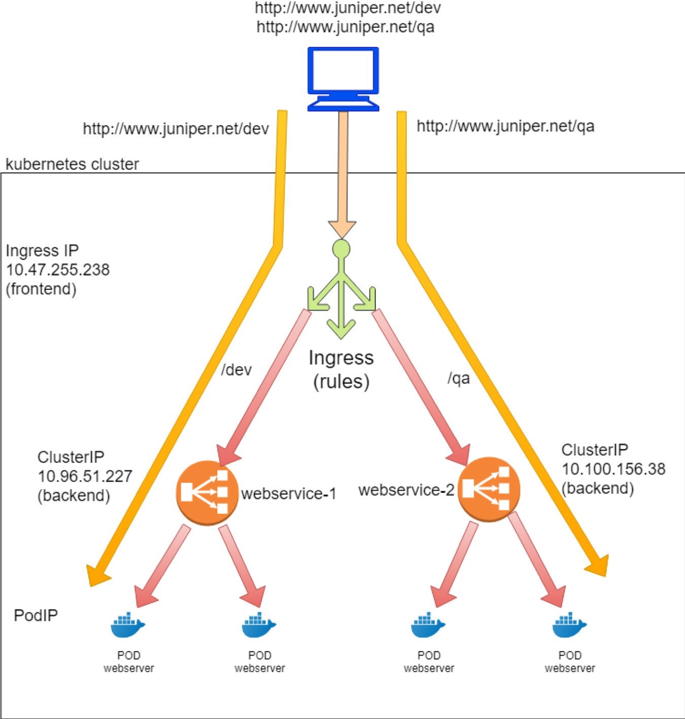
With simple fanout Ingress, based on the URL path and rules, an ingress load balancer directs traffic to different backend services like so:
www.juniper.net/qa --| |-> webservice-1
| 101.101.101.1 | www.juniper.net/dev -| |-> webservice-2
To demonstrate simple fan-out type of ingress, the objects that we need to create are:
An Ingress object: it defines the rules, mapping two paths to two backend services
Two backend services objects
Each service requires at least one pod as a backend
The same client pod as the cluster-internal client used in previous examples.
Ingress Objects Definition
The goals of the simple fanout Ingress test lab for host www.juniper.net are:
Requests toward path /dev will be directed to a service webservice-1 with servicePort 8888.
Requests toward path /qa will be directed to a service webservice-2 with servicePort 8888. Here is the corresponding YAML file to implement these goals:
In contrast to single service Ingress, in simple fanout Ingress object (and name-based virtual host Ingress) you can see rules defined – here it is the mappings from multiple paths to different backend services.
Backend Service Definition
Since we defined two rules each for a path, you need two services, accordingly. You can clone the previous service in the single service Ingress example and just change that service’s name and selector to generate the second service. For example, this is definition of webservice-1 and webservice-2 service:
Backend Pod Definition
Because there are two backend services now, you also need at least two backend pods each with a label matching to a service. You can clone the previous Deployment into two and just change the name and label of the second Deployment.
The Deployment for webserver-1:
And the Deployment for webserver-2:
Deploy Simple Fanout Ingress
Just as in the single service Ingress, you put everything together to get an all-in-one YAML file to test simple fanout Ingress:
Now apply the all-in-one YAML file to create all objects:
The ingress, two service, and two Deployment objects are now created.
Ingress Post Examination
$ kubectl get ingresses.extensions
NAME HOSTS ADDRESS PORTS AGE
ingress-sf www.juniper.net 10.47.255.238,101.101.101.1 80 7s
$ kubectl get
ingresses.extensions -o
yaml apiVersion: v1
items:
- apiVersion:
extensions/v1beta1
kind: Ingress
metadata:
annotations:
kubectl.kubernetes.io/last-applied-configuration: |
{"apiVersion":"extensions/v1beta1","kind":"Ingress","metadata":{"annotations":{},"name
":"ingress-sf","namespace":"ns-user-1"},"spec":{"rules
":[{"host":"www.juniper.net","http":{"paths":[{"backend":{"serviceName":"webservice-1",
"servicePort":8888},"path":"/dev"},{"backend":{"service Name":"webservice-
2","servicePort":8888},"path":"/qa"}]}}]}}
creationTimestamp: 2019-
08-13T06:00:28Z
generation: 1
name: ingress-sf
namespace: ns-user-1
resourceVersion: "860530"
selfLink: /apis/extensions/v1beta1/namespaces/ns-user-1/ingresses/ingress-sf
uid: a6e801fd-bd8f-11e9-9072-0050569e6cfc
spec:
rules:
- host: www.juniper.net
http:
paths:
- backend:
serviceName: webservice-1
servicePort: 8888
path: /dev
- backend:
serviceName: webservice-2
servicePort: 8888
path: /qa
status:
loadBalancer:
					ingress:
					- ip: 101.101.101.1
					- ip: 10.47.255.238
kind:
List
metadata:
resourceVersion:
"" selfLink: ""
The rules are defined properly, and within each rule there is a mapping from a path to the corresponding service. You can see the same ingress internal podIP and external floating IP as seen in the previous single service Ingress example:
That is why, from the gateway router’s perspective, there are no differences between all the types of ingress. In all cases, a public floating IP will be allocated to the ingress and it is advertised to the gateway router:
labroot@camaro> show route table k8s-test protocol bgp

k8s-test 7 destinations, 7 routes (7 active, 0 holddown, 0 hidden) @ = Routing Use Only, # = Forwarding Use Only
+ = Active Route, - = Last Active, * = Both
101.101.101.1/32 *[BGP/170] 02:46:13, MED 100, localpref 200, from 10.169.25.19
AS path: ?
validation-state: unverified, > via gr-2/2/0.32771, Push 61
Now, check the backend services and pods. First the service objects:
$ kubectl get svc -o wide
NAME	TYPE	CLUSTER-IP	EXTERNAL-IP PORT(S) AGE SELECTOR
webservice-1   ClusterIP  10.96.51.227   <none>	8888/TCP 68d app=webserver-1 webservice-2   ClusterIP  10.100.156.38  <none>		8888/TCP 68d app=webserver-2
Then the backend and client pods:
$ kubectl get pod -o wide
NAME	READY  STATUS   ... AGE IP	NODE ..
client	1/1 Running ... 44d 10.47.255.237 cent222 ..
webserver-1-846c9ccb8b-wns77 1/1 Running ... 13m 10.47.255.236 cent333 .. webserver-2-846c9ccb8b-t75d8 1/1 Running ... 13m 10.47.255.235 cent333 ..

$ kubectl get pod -o wide -l app=webserver-1
NAME	READY  STATUS   ... AGE IP	NODE ..
webserver-1-846c9ccb8b-wns77 1/1 Running ... 156m 10.47.255.236 cent333 ..

$ kubectl get pod -o wide -l app=webserver-2
NAME	READY  STATUS   ... AGE IP	NODE ..
webserver-2-846c9ccb8b-t75d8 1/1 Running ... 156m 10.47.255.235 cent333 ..
Two services are created, each with a different allocated clusterIP. For each service there is a backend pod. Later, when we verify ingress from the client, we’ll see these podIPs in the returned web pages.
Contrail Ingress Load Balancer Object
Compared with single service Ingress, the only difference is one more service load balancer as shown in the next screen capture.
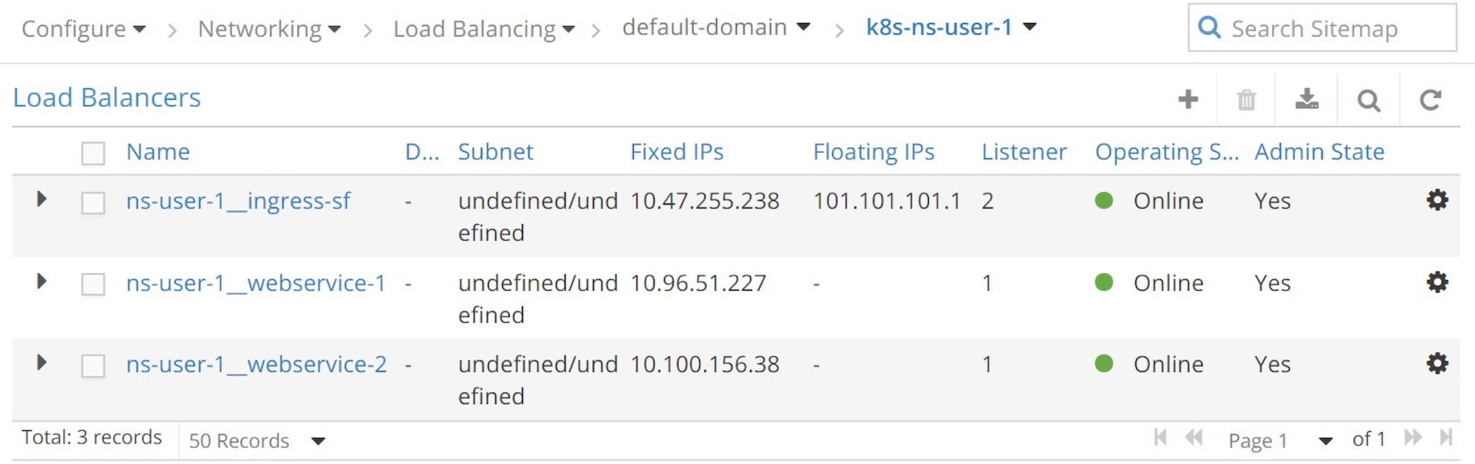
Simple Fanout Ingress Load Balancers (UI: configuration > Networking > Floating IPs)The three load balancers generated in this test are:
Load balancer ns-user-1 ingress-sf for ingress ingress-sf
Load balancer ns-user-1 webservice-1 for service webserver-1
Load balancer ns-user-1 webservice-2 for service webserver-2
We won’t explore the details of the objects again since we’ve investigated the key parameters of service and Ingress load balancers in single service Ingress and there is really nothing new here
Haproxy Process and Haproxy.cfg File
In the single service Ingress example, we demonstrated two haproxy processes invoked by contrail-svc-monitor when it sees loadbalancer appearing with loadbalancer_provider and set to opencontrail. At the end of that example, after we removed the single service Ingress, since there is no more Ingress left in the cluster, the two haproxy processes will be ended. Now, with a new ingress creation, the two new haproxy processes are invoked again:
Node cent222:
$ ps aux | grep haproxy
188   29706  0.0  0.0  55572   2940  ?	Ss 04:04 0:00 haproxy
-f /var/lib/contrail/loadbalancer/haproxy/b32780cd-ae02-11e9-9c97-002590a54583/haproxy.conf
-p /var/lib/contrail/loadbalancer/haproxy/b32780cd-ae02-11e9-9c97-002590a54583/haproxy.pid
-sf 29688
Node cent333:
[root@b4s42 ~]# ps aux | grep haproxy
188   1936  0.0  0.0  55572   896  ?	Ss 04:04 0:00 haproxy
-f /var/lib/contrail/loadbalancer/haproxy/b32780cd-ae02-11e9-9c97-002590a54583/haproxy.conf
-p /var/lib/contrail/loadbalancer/haproxy/b32780cd-ae02-11e9-9c97-002590a54583/haproxy.pid
-sf 1864
This time what interests us is how the simple fanout Ingress rules are programmed in the haproxy.conf file. Let’s look at the haproxy configuration file:
The configuration file is formatted slightly to make it fit to a page width.
The configuration looks a little bit more complicated than the one for single service Ingress, but the most important part of it looks pretty straightforward:
The haproxy frontend section: It now defines URLs. Each URL is represented by a pair of acl statements, one for the host, and the other for the path. In a nutshell, host is the domain name and path is what follows the host in the URL string. Here, for simple fanout Ingress there is the host www.juniper. net with two different paths: \dev and \qa.
The haproxy backend section: Now there are two of them. For each path there is a dedicated service.
The use_backend…if… command in the frontend section: This statement declares the ingress rules – if the URL request includes a specified path that matches to what is programmed in one of the two ACL pairs, use the corresponding backend (that is a service) to forward the traffic.
For example, acl 020e371c-e222-400f-b71f-5909c93132de_path path /qa defines path /qa. If the URL request contains such a path, haproxy will use_backend 020e371c-e222-400f-b71f-5909c93132de, which you can find in the backend section. The backend is a UUID referring to server c13b0d0d-6e4a-4830-bb46-2377ba4caf23 10.100.156.38:8888 weight 1, which is essentially a service. You can identify this by look- ing at the serviceIP:port: 10.100.156.38:8888.
The configuration file is illustrated in Figure 10.
With this proxy.conf file, the haproxy implements our simple fanout Ingress:
If the full URL is composed of host www.juniper.net and path /dev, the request will be dispatched to webservice-1 (10.96.51.227:8888).
If the full URL is composed of host www.juniper.net and path /qa, the request will be dispatched to webservice-2 (10.100.156.38:8888).
For any other URLs the request will be dropped because there is no corresponding backend service defined for it.
In practice, you often need the default_backend service to process all those HTTP requests with no matching URLs in the rules. We’ve seen it in the previous example of single service Ingress. Later in the name-based virtual hosting Ingress section we’ll combine the use_backend and default_backend together to provide this type of flexibility.
Ingress Verification: from Internal
Let’s test the URL with different paths:
$ kubectl exec -it client -- \
					curl -H 'Host:www.juniper.net'
								 10.47.255.238/dev | w3m -T
 							text/html | cat Hello
						This page is served
						by a Contrail pod
						IP address =
						10.47.255.236
						Hostname = webserver-1-846c9ccb8b-wns77
$ kubectl exec -it client -- \
					curl -H 'Host:www.juniper.net'
								 10.47.255.238/dev | w3m -T
 							text/html | cat Hello
						This page is served
						by a Contrail pod
						IP address =
						10.47.255.236
						Hostname = webserver-1-846c9ccb8b-wns77
$ kubectl exec -it client -- \
					curl -H 'Host:www.juniper.net'
				 10.47.255.238/abc | w3m -T text/html | cat
				503 Service Unavailable
				No server is available to handle this request.
$ kubectl exec -it client -- \
					curl -H 'Host:www.juniper.net'
				 10.47.255.238/abc | w3m -T text/html | cat 503
				Service Unavailable
				No server is available to handle this request.
$ kubectl exec -it client -- \
					curl -H 'Host:www.cisco.com'
				 10.47.255.238/abc | w3m -T text/html | cat 503
				Service Unavailable
				No server is available to handle this request.
The returned output shows the Ingress works: the two requests towards the /qa and /dev paths are proxied to two different backend pods through two backend services: webservice-1 and webservice-2, respectively.
The third request with a path abc composes an unknown URL which does not have a matching service in Ingress configuration, so it won’t be served. It’s the same for the last two requests. Without a path, or with a different host, the URLs become unknown to the ingress so they won’t be served.
You may think that you should be adding more rules to include these scenarios. Doing that works fine, but it’s not scalable – you can never cover all the possible paths and URLs that could come into your server. As we mentioned earlier, one solution is to use the default_backend service to process all other HTTP requests, which happens to be covered in the next example.
Ingress Verification: From External (Internet Host)
When you test simple fanout Ingress from outside of the cluster, the command is the same as what you’ve done for initiating the HTTP request from inside of a pod, except this time you are initiating from an Internet host. Let’s send the HTTP requests to the ingress’s public floating IP, instead of its internal podIP. So, from an Internet host machine:
$ curl -H 'Host:www.juniper.net' 101.101.101.1/qa | w3m -T text/html | cat
											Hello
								This page is served
									by a Contrail pod
									IP address =
									10.47.255.235
								Hostname = Vwebserver-2-
									846c9ccb8b-t75d8 [giphy]
$ curl -H 'Host:www.juniper.net' 101.101.101.1/dev | w3m -T text/html | cat
											Hello
								This page is served
								by a Contrail pod
								IP address =
								10.47.255.236
							Hostname = webserver-
								846c9ccb8b-wns77
								[giphy]
$ curl -H 'Host:www.juniper.net'
				 101.101.101.1/ | w3m -T text/html | cat
				503 Service Unavailable
				No server is available to handle this request.
$ curl -H 'Host:www.juniper.net'
				 101.101.101.1/abc | w3m -T text/html | cat
					503 Service Unavailable
					No server is available to handle this request.
$ curl -H 'Host:www.cisco.com'
				 101.101.101.1/dev | w3m -T text/html | cat
 			503 Service Unavailable
				No server is available to handle this request.
Virtual Hosting Ingress
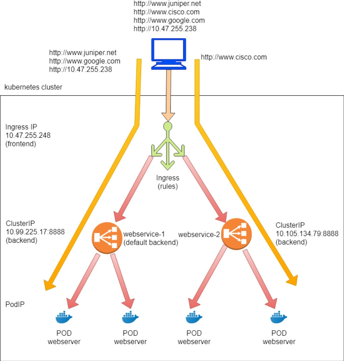
Virtual hosting ingress supports routing HTTP traffic to multiple host names at the same IP address. Based on the URL and the rules, an ingress load balancer directs traffic to different backend services, and each service directs traffic to its backend pods, like in this diagram:
www.juniper.net --|	|-> webservice-1
						| 101.101.101.1 |
				www.cisco.com  --|	|-> webservice-2
To demonstrate the virtual host type of ingress, the objects that we need to create are same as the previous simple fanout Ingress:
An Ingress object: the rules that map two URLs to two backend services
Two backend services objects
Each service requires at least one pod as a backend
Ingress Objects Definition
In the virtual host ingress test lab,
we defined the following rules:
A request toward URL www.juniper.net will be directed to a service webservice-1 with servicePort 8888.
A request toward URL www.cisco.com will be directed to a service webservice-2 with servicePort 8888.
A request toward any URLs other than these two, will be directed to webservice-1 with servicePort 8888. Effectively we want webservice-1 to become the default backend service.
And here is the corresponding YAML definition file:
Backend Service and Pod Definition.
The same exact service and Deployment definition that were used in simple fanout Ingress can be used here. And to be even briefer, here’s the all-in-one YAML file:
Now let’s apply the all-in-one YAML file to create ingress and the other necessary objects:
You can see that the Ingress, two services, and two Deployment objects have now been created.
Ingress Post Examination Let’s examine the Ingress object:
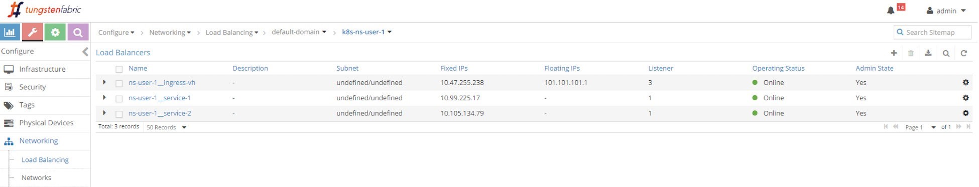
$ kubectl get ingresses.extensions -o wide
	NAME	  HOSTS	  ADDRESS    PORTS AGE
ingress-vh  www.juniper.net,www.cisco.com  10.47.255.238,101.101.101.1  80  8m27s
Compared to simple fanout Ingress, this time you can see two hosts instead of one. Each host represents a domain name:
The rules are defined properly, and within each rule there is a mapping from a host to the corresponding service. Note that the services, pods, and floating IP prefix advertisement to gateway router behavior are all exactly the same as those in simple fanout Ingress.
Exploring Ingress Load Balancer Objects
Three load balancers were generated after we applied the all-in-one YAML file, one for ingress, and two for services.
Load balancers created in this test are almost the same as the ones created in simple fanout Ingress test, as shown in the next screen capture, Figure 11.
Okay so let’s check the haproxy configuration file for name-based
virtual host Ingress. Here’s an examination of the haproxy.conf file:
And here are the highlights:
The haproxy frontend section defines each URL, or host, and its path. Here the two hosts are www.juniper.net and www.cisco.com and for both path is /.
The haproxy backend section defines the servers, which is all service in our case. It has a format of serviceIP:servicePort, which is what the service created.
The use_backend…if… command in the frontend section declares the ingress rules: if the request includes a specified URL and path, use the corresponding backend to forward the traffic.
The default_backend defines the service that will act as the default: it will be used when a haproxy receives a URL request that has no explicit match in the defined rules.
The workflow of the configuration file is illustrated in Figure 12.
Workflow Through the configuration, the haproxy implements our ingress:
If www.juniper.net and / compose the full URL, request will be dispatched to webservice-1 (10.99.225.17:8888).
If www.cisco.net and / compose the full URL, request will be dispatched to webservice-2 (10.105.134.79:8888).
Other URLs go to the default backend, which is service
webservice-1. Let’s go ahead and verify these behaviors.
Ingress Verification: From Internal
From inside of cluster:
$ kubectl exec -it client -- \
				curl -H 'Host:www.juniper.net'
								10.47.255.238:80 | w3m -T
								text/html | cat Hello
						This page is served
							by a Contrail pod
							IP address =
							 10.47.255.236
							Hostname = Vwebserver-1-846c9ccb8b-g65dg
$ kubectl exec -it client -- \
				curl -H 'Host:www.cisco.com'
								10.47.255.238:80 | w3m -T
								text/html | cat Hello
						This page is served
							by a Contrail pod
							IP address =
							 10.47.255.236
							Hostname = Vwebserver-1-846c9ccb8b-g65dg
$ kubectl exec -it client -- \
				curl -H 'Host:www.google.com'
								10.47.255.238:80 | w3m -T
								text/html | cat Hello
						This page is served
							by a Contrail pod
							IP address =
							 10.47.255.236
							Hostname = Vwebserver-1-846c9ccb8b-g65dg
$ kubectl exec -it client -- \
				curl 10.47.255.238:80 |
								w3m -T
								text/html | cat
								Hello
						This page is served
						by a Contrail pod
 					IP address =
						10.47.255.236
						Hostname = Vwebserver-1-846c9ccb8b-g65dg
The Ingress works. The two requests towards Juniper and Cisco are proxied to two different backend pods, through two backend services, webservice-1 and webservice-2, respectively. The third request towards Google is an unknown URL, which does not have a matching service in Ingress configuration, so it goes to the default backend service, webservice-1, and reaches the same backend pod.
The same rule applies to the fourth request. When not given a URL using -H, curl will fill the host with the request IP address, in this case 10.47.255.238. Since that URL doesn’t have a defined backend service, the default backend service will be used. In our lab, we use backend pods for each service spawned by the same Deployment, so the podIP in a returned webpage tells us who is who. Except in the second test the returned podIP was 10.47.255.235, representing webservice-2, while the other three tests returned the podIP for webservice-1, as expected.
Ingress Verification: from External (Internet host)
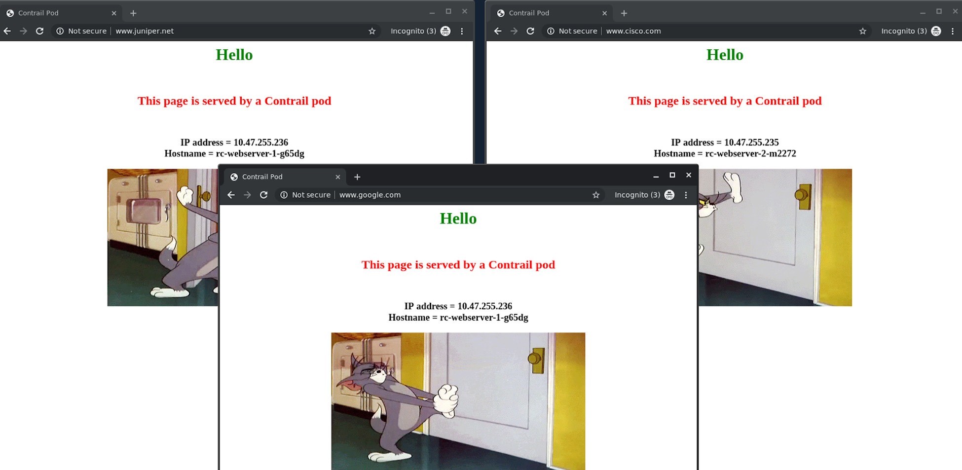
From an Internet host’s desktop, we launched two Chrome pages side-by-side and input www.juniper.net in one and www.cisco.com in the other, and kept refreshing the pages. We can confirm that the Juniper page is always returned by the Deployment webserver-1 pod 10.47.255.236, and the Cisco page is always returned by the Deployment webserver-2 pod 10.47.255.235. Then we launched a third Chrome page towards www.google.com, and it was returned by the same pod serving the Juniper instance, as shown by the screen shots in Figure 13.
The same result can be seen from curl, too. Here it’s shown from the Internet host machine:
$ curl -H 'Host:www.juniper.net' 101.101.101.1 | w3m -T text/html | cat
									Hello
							This page is served
								by a Contrail pod
								IP address =
								10.47.255.236
								Hostname = Vwebserver-1-846c9ccb8b-g65dg
$ curl -H 'Host:www.cisco.com'  101.101.101.1 | w3m -T text/html | cat
									Hello
							This page is served
								by a Contrail pod
								IP address =
								10.47.255.236
								Hostname = Vwebserver-1-846c9ccb8b-g65dg
$ curl -H 'Host:www.google.com'  101.101.101.1 | w3m -T text/html | cat
									Hello
							This page is served
								by a Contrail pod
								IP address =
								10.47.255.236
								Hostname = Vwebserver-1-846c9ccb8b-g65dg
$ curl 101.101.101.1 | w3m -T text/html | cat
								Hello
						This page is served
						 by a Contrail pod
						IP address =
						10.47.255.236
						Hostname = Vwebserver-1-846c9ccb8b-g65dg
Service Versus Ingress Traffic Flow
Even though both service and ingress are implemented via load balancers (but with different loadbalancer_ provider types), the forwarding modes for service and ingress are quite different. With service forwarding it’s a one-hop process: the client sends the request to the clusterIP or the floating IP. With NAT, the request reaches the destination backend pod; while with Ingress forwarding, the traffic takes a two-hop process to arrive at the destination pod. The request first goes to the active haproxy, which then starts a HTTP/HTTPS level proxy procedure and does the service forwarding to reach the final pod. NAT processing happens in both forwarding processes, since both ingress and service public floating IP implementation relies on it.
Chapter 7 provides a detailed view of this Contrail packet flow.