Related Procedures
The following procedures are referenced by the upgrade procedures.
Servicing the CTP2000 CPU
This topic describes how to remove the CTP2000 CPU from the chassis for service or upgrade, and how to return the CPU to the chassis. Follow proper antistatic procedures when you perform the following procedures.
To remove the CPU from the CTP2000 chassis:
- Ground yourself by using an antistatic wrist strap or other device, and connect it to one of the ESD grounding jacks, if available, or another grounding device.
- Power off the unit.
- If an Ethernet cable is connected to the CPU (PP310 only), disconnect the cable.
- Using a Phillips screwdriver, loosen each of the retaining screws on the outside edge of the CPU until the ejector that the screw secures is released.
- Use the ejectors to remove the card from the chassis.
To return the CPU to the chassis:
- Guide the CPU into the chassis by placing it between the
guides of the slot and pushing the module until it stops.
The module stops sliding when the ejectors make contact with the chassis.
- Tighten each of the retaining screws on the outside edge of the CPU.
- If an Ethernet cable was connected to the CPU (PP310 only), reconnect the cable.
Installing or Replacing CTP2000 DRAM Memory Modules in the PP310 or PP332 CPU
The PP310 accepts standard 200-pin DDR SODIMM modules fitted with 2.5V PC2100 DDR SDRAM without ECC. ECC is supported by devices soldered onto the board. Two sockets are provided that can accommodate SODIMMs of 512 MB or 1 GB capacities.
The PP332 accepts standard 200-pin DDR SODIMM modules fitted with 2.5V PC2100 or PC2700 DDR SDRAM. Both 64-bit non-ECC SODIMM modules and 72-bit ECC SODIMM modules are supported. If ECC is required, then ECC modules must be fitted. Two sockets are provided that can accommodate modules up to 1 GB capacity each
When fitting only one SODIMM (for either CPU) this must be in the SODIMM #1 position.
To install or replace a memory module in the PP310 CPU:
- Ground yourself by using an antistatic wrist strap or other device, and connect it to one of the ESD grounding jacks, if available, or another grounding device.
- Remove the new memory module from its antistatic bag.
- Remove the CPU board from the CTP2000 chassis. See Servicing the CTP2000 CPU.
- To remove a memory module:
Release the memory module by using your thumb to raise the end of the memory module to the angle shown in Figure 5.
Note Figure 5 shows the PP310 CPU. The memory module is removed and replaced in the same manner for the PP332 CPU.
Hold the memory module between your thumb and forefinger and gently pull it out of the socket.
Figure 5: DRAM Memory Module Replacement — PP310 
- To insert the new memory module:
Hold the module between your thumb and forefinger and insert one end into the socket at the angle shown in Figure 5.
Lower the free end of the module until it snaps into place.
- Return the CPU to the chassis and secure it in place. See Servicing the CTP2000 CPU.
Restoring BIOS Defaults for the CTPOS 7.0R1 and Later Upgrade (PP310)
You must restore default BIOS settings (stored in CMOS) during the CTPOS 7.0R1 upgrade process for the PP310. Refer to Figure 6 when performing the following procedure.
To restore default BIOS settings:
- Remove the CPU from the CTP2000 device chassis. See Servicing the CTP2000 CPU.
- Locate the BIOS reset pins, which are shown as two black
circles inside a figure 8 and captioned as CMOS Clear.
Note The two BIOS reset pins are the only reset pins that are used in this procedure.
- Attach the BIOS reset jumper included in the CTP2000 upgrade kit to the BIOS reset pins in order to short them together.
- Insert the CPU into the device. See Servicing the CTP2000 CPU.
- Apply power to the device for 10 seconds.
- Power off the device.
- Remove the CPU from the chassis.
- Remove the BIOS reset jumper so that the BIOS reset pins are no longer shorted together.
- Insert the CPU into the device. When you power on the device, the default BIOS settings will be in effect.
Installing or Removing a CTP2000 Series CompactFlash Card
On the CTP2000 series devices with the new PP833 processor, the CompactFlash card is installed on the processor itself (which may be located under an installed PMC card), which prevents insertion or removal of the CompactFlash card until the PMC card is removed. On the CTP2000 series devices with the PP310 and PP332 processors, the CompactFlash card is installed on the processor rear transition module (RTM). Some CTP devices may ship with a CompactFlash card already installed.
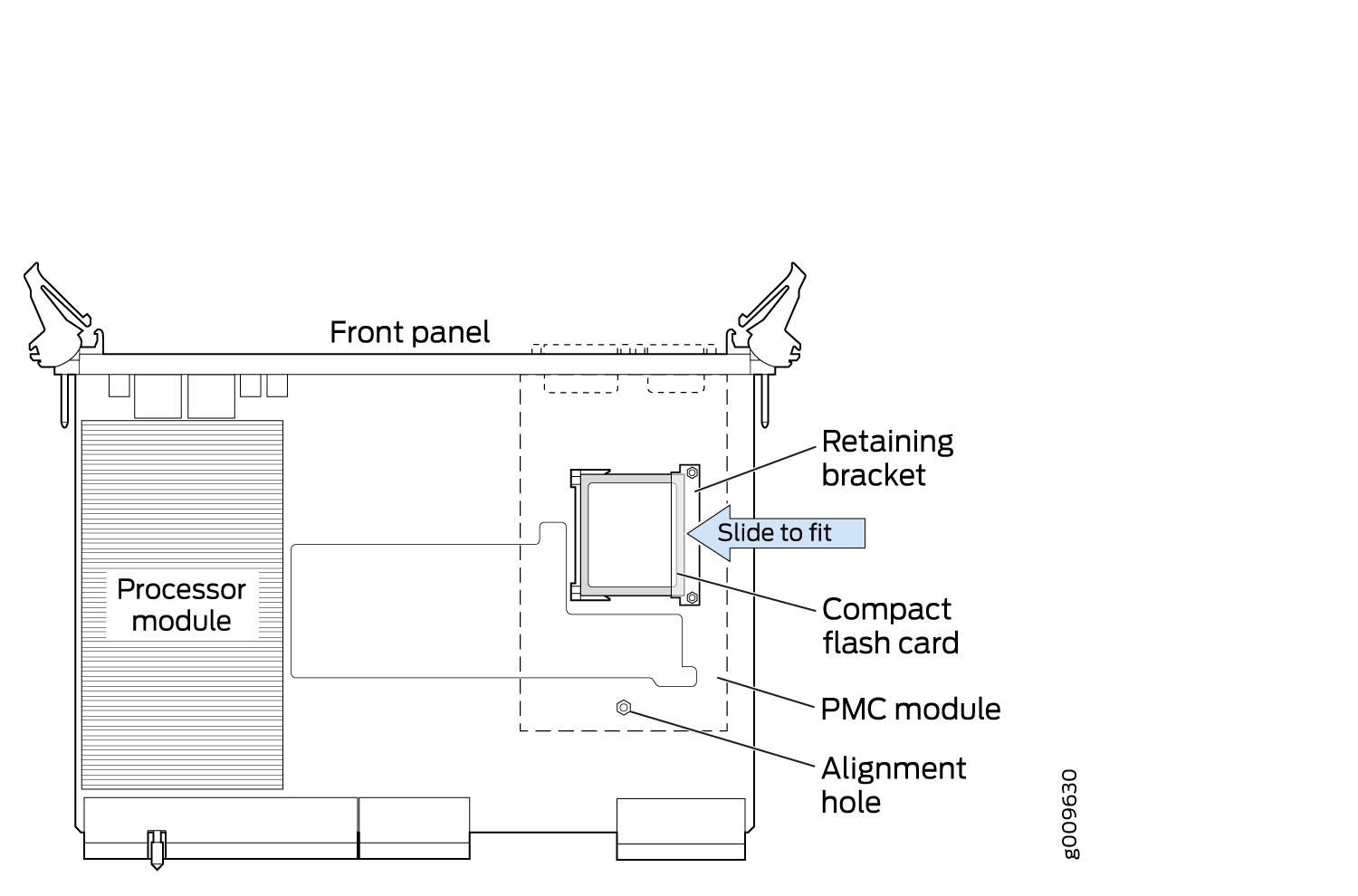
To remove or install the CompactFlash card for the CTP2000 series with the new PP833 processor (see Figure 7):
- Power off the unit.
- If installed, remove the PP833 PMC card by unscrewing the retaining screws and pushing the extractors outward with the latching buttons depressed.
- You can then remove or install the CompactFlash card in the flash socket.
- If being used, reinstall the PP833 PMC card into the chassis, and secure the retaining screws.
To remove or install the CompactFlash card for the CTP2000 series with the PP310 and PP332 processors (see Figure 8):
- Power off the unit.
- Remove the processor RTM by unscrewing the retaining screws and pushing the extractors outward with the latching buttons depressed.
- Remove the CompactFlash card retaining screw and nut. You can then remove or install the CompactFlash card in the flash socket (see Figure 8).
- Reinstall the CompactFlash card retaining screw and nut.
- Reinstall the processor RTM into the chassis, and secure the retaining screws.