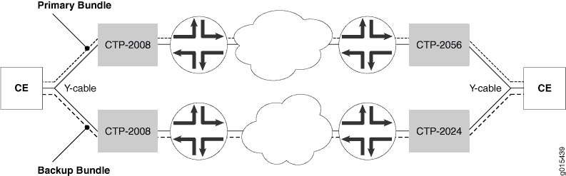
Bundle Failover Between CTP Devices at Both the Local and Remote Site Overview
You can use Y cables at both the local and remote sites to provide a redundant path for bundles. This feature is also known as double-ended Y-cable redundancy. As shown in Figure 3, you use a Y cable to connect two CTP devices to the customer equipment (CE) at both sites. You then create a primary bundle between one pair of CTP devices, and you create a backup bundle between a second pair of CTP devices.
How Bundle Failover Between CTP Devices at Both the Local and Remote Sites Works
Under normal conditions, both the primary and backup bundles are in the running state and are consuming bandwidth. Under these conditions, the primary bundle is carrying the data between the CEs.
If the primary bundle goes down or is no longer in the running state, the CTP devices switch over to the backup bundle, and the backup bundle carries the data. The time that it takes for the switchover to occur depends on the bundle configuration. The switchover happens faster if you enable the Fast Switch option. The actual switchover time depends on the circuit packet rate and the configured packets to starvation parameter, but it is on the order of milliseconds instead of seconds. This option may not be used in conjunction with Cold Standby. Fast switch is supported only in Hot standby in Revert redundancy mode and is valid only for a hardware link.
When the primary bundle returns to the running state, the CTP devices switch back to the primary bundle, and the primary bundle begins carrying data.
Requirements for Y-Cable Redundancy
Keep the following in mind when you use Y-cable redundancy:
Starting from CTPOS Release 7.0, CTP2000 devices support Y-cable redundancy on both serial and T1/E1 interfaces. CTPOS Releases 6.6 and earlier support Y-cable redundancy only on serial interfaces.
Starting from CTPOS Release 6.6, CTP150 devices support Y-cable redundancy on both serial and T1/E1 interfaces. CTPOS Releases 6.5 and earlier support Y-cable redundancy only on serial interfaces.
Y-cable redundancy can be based on either a hardware link that uses a special Y cable or a software link that uses OAM packets, which port pairs use to communicate with each other. A hardware link is supported only on serial ports. When the hardware link is enabled, the Y cable provides control leads between the two CTP devices in addition to the standard signal, clock, and data leads connected to the attached device. There is one Y cable for CTP2000 devices and another Y cable for CTP150 devices. Therefore, you must use the same platform type at each site.
A software link does not require a special signaling hardware. Y-cable port pairs can maintain contact with each other by using the OAM packets instead of a hardware signaling path. Because of this, Y-cable redundancy is supported on T1/E1 ports as well as serial ports.
The Y cable is short to maintain signal quality. The two CTP devices connected to the Y cable must be in close proximity to each other.
To run diagnostics on a nonactive bundle attached to a Y cable without introducing data errors on the active bundle, Y-cable redundancy must be configured, and you cannot have a daughter card installed.
Clocking Supported with Y-Cable Redundancy
Y-cable redundancy is supported with the following clock configurations:
Configured rate without external TX clock (TT).
Configured rate with external TX clock (TT).
All clocked with external TX clock (TT).
Adaptive clocking with internal clock.
Adaptive clocking with external TX clock (TT).