Bundle Failover Between CTP Devices at the Same Site Overview
Y-cable redundancy provides bundle failover using CTP devices at the same site. It provides a way to back up a CTP device with a redundant device at the same site, which increases circuit availability to a site (typically a remote site). The purpose of this redundancy scheme is to maximize network availability by providing complete hardware redundancy that protects from failures that include the network, chassis, processor, power supplies, and the interface module. It quickly restores communication when a system is not reachable or has failed, and is especially valuable at locations that do not have maintenance personnel or spare parts.
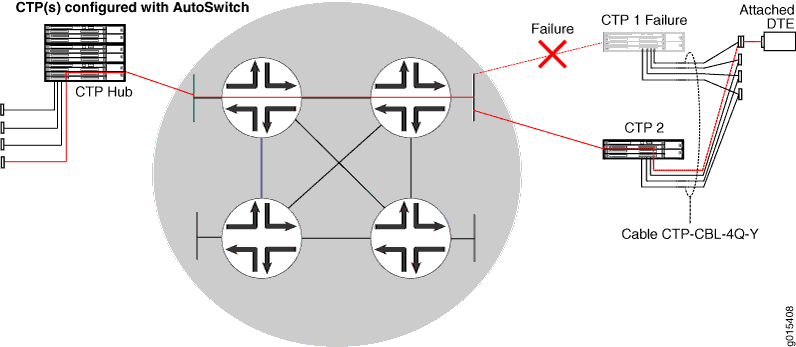
As shown in Figure 2, during a network or equipment failure, the affected circuit is switched to a co-located alternate CTP device and port. The process of switching the circuit to the redundant system is controlled by the AutoSwitch feature running at the hub CTP system. You need to configure AutoSwitch at the CTP hub location.

To use this feature, you use a Y cable to connect the active and standby CTP devices. With this feature enabled, the active CTP device passes data and generates keepalive messages with the standby CTP device over the Y cable. If a failure occurs, the standby CTP device becomes active and transmits data on the circuit.
Requirements for Y-Cable Redundancy
Keep the following in mind when you use Y-cable redundancy:
Starting from CTPOS Release 7.0, CTP2000 devices support Y-cable redundancy on both serial and T1/E1 interfaces. CTPOS Releases 6.6 and earlier support Y-cable redundancy only on serial interfaces.
Starting from CTPOS Release 6.6, CTP150 devices support Y-cable redundancy on both serial and T1/E1 interfaces. CTPOS Releases 6.5 and earlier support Y-cable redundancy only on serial interfaces.
Y-cable redundancy can be based on either a hardware link that uses a special Y cable or a software link that uses OAM packets, which port pairs use to communicate with each other. A hardware link is supported only on serial ports. When the hardware link is enabled, the Y cable provides control leads between the two CTP devices in addition to the standard signal, clock, and data leads connected to the attached device. There is one Y cable for CTP2000 devices and another Y cable for CTP150 devices. Therefore, you must use the same platform type at each site.
A software link does not require a special signaling hardware. Y-cable port pairs can maintain contact with each other by using the OAM packets instead of depending on a hardware signaling path. Because of this, Y-cable redundancy is supported on T1/E1 ports as well as serial ports.
The Y cable is short to maintain signal quality. The two CTP devices connected to the Y cable must be in close proximity to each other.
To run diagnostics on a nonactive bundle attached to a Y cable without introducing data errors on the active bundle, Y-cable redundancy must be configured, and you cannot have a daughter card installed.
Clocking Supported with Y-Cable Redundancy
Y-cable redundancy is supported with the following clock configurations:
Configured rate without external TX clock (TT).
Configured rate with external TX clock (TT).
All clocked with external TX clock (TT).
Adaptive clocking with internal clock.
Adaptive clocking with external TX clock (TT).
