Auf dieser Seite
Beispiel: Ankündigung mehrerer Pfade in BGP
In diesem Beispiel sind BGP-Router so konfiguriert, dass sie mehrere Pfade ankündigen, anstatt nur den aktiven Pfad anzukündigen. Die Ankündigung mehrerer Pfade in BGP ist in RFC 7911, Ankündigung mehrerer Pfade in BGP, spezifiziert.
Anforderungen
In diesem Beispiel werden die folgenden Hardware- und Softwarekomponenten verwendet:
Acht BGP-fähige Geräte.
Fünf der BGP-fähigen Geräte müssen nicht zwangsläufig Router sein. Dies können beispielsweise Ethernet-Switches der EX-Serie sein.
Drei der BGP-fähigen Geräte sind so konfiguriert, dass sie mehrere Pfade senden oder mehrere Pfade empfangen (oder mehrere Pfade senden und empfangen). Bei diesen drei BGP-fähigen Geräten muss es sich um Multiservice-Edge-Router der M-Serie, universelle 5G-Routing-Plattformen der MX-Serie oder Core-Router der T-Serie handeln.
Auf den drei Routern muss Junos OS Version 11.4 oder höher ausgeführt werden.
Überblick
Die folgenden Anweisungen werden verwendet, um mehrere Pfade zu einem Ziel zu konfigurieren:
[edit protocols bgp group group-name family family]
add-path {
    receive;
    send {
        include-backup-path include-backup-path;
        multipath;
        path-count path-count;
        path-selection-mode {
            (all-paths | equal-cost-paths);
        }
        prefix-policy [ policy-names ... ];
    }
}
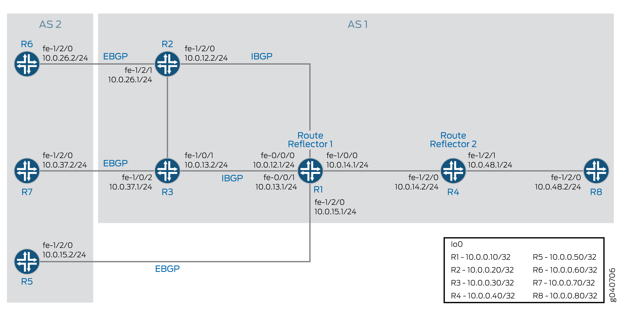
In diesem Beispiel verteilen Router R5, Router R6 und Router R7 statische Routen in BGP neu. Router R1 und Router R4 sind Routenreflektoren. Router R2 und Router R3 sind Clients für Route Reflector R1. Router R8 ist ein Client für Route Reflector R4.
Die Routenreflektion ist optional, wenn die Ankündigung mehrerer Pfade in BGP aktiviert ist.
Mit der Konfiguration ist Router R1 so konfiguriert, dass bis zu sechs Pfade (pro Ziel) an Router R4 gesendet werden.add-path send path-count 6
Mit der Konfiguration wird Router R4 so konfiguriert, dass er mehrere Pfade von Router R1 empfängt.add-path receive
Mit der Konfiguration ist Router R4 so konfiguriert, dass bis zu sechs Pfade an Router R8 gesendet werden.add-path send path-count 6
Mit der Konfiguration ist Router R8 so konfiguriert, dass er mehrere Pfade von Router R4 empfängt.add-path receive
Die Richtlinienkonfiguration (zusammen mit dem entsprechenden Routing-Filter) schränkt Router R4 darauf ein, mehrere Pfade nur für die Route 172.16.199.1/32 zu senden.add-path send prefix-policy allow_199
Topologiediagramm
Abbildung 1 Zeigt die in diesem Beispiel verwendete Topologie.
Konfiguration
- CLI-Schnellkonfiguration
- Konfigurieren von Router R1
- Konfigurieren von Router R2
- Konfigurieren von Router R3
- Konfigurieren von Router R4
- Konfigurieren des Routers R5
- Konfigurieren des Routers R6
- Konfigurieren des Routers R7
- Konfigurieren von Router R8
- Ergebnisse
CLI-Schnellkonfiguration
Um dieses Beispiel schnell zu konfigurieren, kopieren Sie die folgenden Befehle, fügen Sie sie in eine Textdatei ein, entfernen Sie alle Zeilenumbrüche, ändern Sie alle Details, die für Ihre Netzwerkkonfiguration erforderlich sind, und kopieren Sie dann die Befehle und fügen Sie sie in die CLI auf Hierarchieebene ein.[edit]
Router R1
set interfaces fe-0/0/0 unit 12 family inet address 10.0.12.1/24
set interfaces fe-0/0/1 unit 13 family inet address 10.0.13.1/24
set interfaces fe-1/0/0 unit 14 family inet address 10.0.14.1/24
set interfaces fe-1/2/0 unit 15 family inet address 10.0.15.1/24
set interfaces lo0 unit 10 family inet address 10.0.0.10/32
set protocols bgp group rr type internal
set protocols bgp group rr local-address 10.0.0.10
set protocols bgp group rr cluster 10.0.0.10
set protocols bgp group rr neighbor 10.0.0.20
set protocols bgp group rr neighbor 10.0.0.30
set protocols bgp group e1 type external
set protocols bgp group e1 neighbor 10.0.15.2 local-address 10.0.15.1
set protocols bgp group e1 neighbor 10.0.15.2 peer-as 2
set protocols bgp group rr_rr type internal
set protocols bgp group rr_rr local-address 10.0.0.10
set protocols bgp group rr_rr neighbor 10.0.0.40 family inet unicast add-path send path-count 6
set protocols ospf area 0.0.0.0 interface lo0.10 passive
set protocols ospf area 0.0.0.0 interface fe-0/0/0.12
set protocols ospf area 0.0.0.0 interface fe-0/0/1.13
set protocols ospf area 0.0.0.0 interface fe-1/0/0.14
set protocols ospf area 0.0.0.0 interface fe-1/2/0.15
set routing-options router-id 10.0.0.10
set routing-options autonomous-system 1
Router R2
set interfaces fe-1/2/0 unit 21 family inet address 10.0.12.2/24
set interfaces fe-1/2/1 unit 26 family inet address 10.0.26.1/24
set interfaces lo0 unit 20 family inet address 10.0.0.20/32
set protocols bgp group rr type internal
set protocols bgp group rr local-address 10.0.0.20
set protocols bgp group rr neighbor 10.0.0.10 export set_nh_self
set protocols bgp group e1 type external
set protocols bgp group e1 neighbor 10.0.26.2 peer-as 2
set protocols ospf area 0.0.0.0 interface lo0.20 passive
set protocols ospf area 0.0.0.0 interface fe-1/2/0.21
set protocols ospf area 0.0.0.0 interface fe-1/2/1.28
set policy-options policy-statement set_nh_self then next-hop self
set routing-options autonomous-system 1
Router R3
set interfaces fe-1/0/1 unit 31 family inet address 10.0.13.2/24
set interfaces fe-1/0/2 unit 37 family inet address 10.0.37.1/24
set interfaces lo0 unit 30 family inet address 10.0.0.30/32
set protocols bgp group rr type internal
set protocols bgp group rr local-address 10.0.0.30
set protocols bgp group rr neighbor 10.0.0.10 export set_nh_self
set protocols bgp group e1 type external
set protocols bgp group e1 neighbor 10.0.37.2 peer-as 2
set protocols ospf area 0.0.0.0 interface lo0.30 passive
set protocols ospf area 0.0.0.0 interface fe-1/0/1.31
set protocols ospf area 0.0.0.0 interface fe-1/0/2.37
set policy-options policy-statement set_nh_self then next-hop self
set routing-options autonomous-system 1
Router R4
set interfaces fe-1/2/0 unit 41 family inet address 10.0.14.2/24
set interfaces fe-1/2/1 unit 48 family inet address 10.0.48.1/24
set interfaces lo0 unit 40 family inet address 10.0.0.40/32
set protocols bgp group rr type internal
set protocols bgp group rr local-address 10.0.0.40
set protocols bgp group rr family inet unicast add-path receive
set protocols bgp group rr neighbor 10.0.0.10
set protocols bgp group rr_client type internal
set protocols bgp group rr_client local-address 10.0.0.40
set protocols bgp group rr_client cluster 10.0.0.40
set protocols bgp group rr_client neighbor 10.0.0.80 family inet unicast add-path send path-count 6
set protocols bgp group rr_client neighbor 10.0.0.80 family inet unicast add-path send prefix-policy allow_199
set protocols ospf area 0.0.0.0 interface fe-1/2/0.41
set protocols ospf area 0.0.0.0 interface lo0.40 passive
set protocols ospf area 0.0.0.0 interface fe-1/2/1.48
set policy-options policy-statement allow_199 from route-filter 172.16.199.1/32 exact
set policy-options policy-statement allow_199 term match_199 from prefix-list match_199
set policy-options policy-statement allow_199 then add-path send-count 20
set policy-options policy-statement allow_199 then accept
set routing-options autonomous-system 1
Router R5
set interfaces fe-1/2/0 unit 51 family inet address 10.0.15.2/24
set interfaces lo0 unit 50 family inet address 10.0.0.50/32
set protocols bgp group e1 type external
set protocols bgp group e1 neighbor 10.0.15.1 export s2b
set protocols bgp group e1 neighbor 10.0.15.1 peer-as 1
set policy-options policy-statement s2b from protocol static
set policy-options policy-statement s2b from protocol direct
set policy-options policy-statement s2b then as-path-expand 2
set policy-options policy-statement s2b then accept
set routing-options autonomous-system 2
set routing-options static route 172.16.199.1/32 reject
set routing-options static route 172.16.198.1/32 reject
Router R6
set interfaces fe-1/2/0 unit 62 family inet address 10.0.26.2/24
set interfaces lo0 unit 60 family inet address 10.0.0.60/32
set protocols bgp group e1 type external
set protocols bgp group e1 neighbor 10.0.26.1 export s2b
set protocols bgp group e1 neighbor 10.0.26.1 peer-as 1
set policy-options policy-statement s2b from protocol static
set policy-options policy-statement s2b from protocol direct
set policy-options policy-statement s2b then accept
set routing-options autonomous-system 2
set routing-options static route 172.16.199.1/32 reject
set routing-options static route 172.16.198.1/32 reject
Router R7
set interfaces fe-1/2/0 unit 73 family inet address 10.0.37.2/24
set interfaces lo0 unit 70 family inet address 10.0.0.70/32
set protocols bgp group e1 type external
set protocols bgp group e1 neighbor 10.0.37.1 export s2b
set protocols bgp group e1 neighbor 10.0.37.1 peer-as 1
set policy-options policy-statement s2b from protocol static
set policy-options policy-statement s2b from protocol direct
set policy-options policy-statement s2b then accept
set routing-options autonomous-system 2
set routing-options static route 172.16.199.1/32 reject
Router R8
set interfaces fe-1/2/0 unit 84 family inet address 10.0.48.2/24
set interfaces lo0 unit 80 family inet address 10.0.0.80/32
set protocols bgp group rr type internal
set protocols bgp group rr local-address 10.0.0.80
set protocols bgp group rr neighbor 10.0.0.40 family inet unicast add-path receive
set protocols ospf area 0.0.0.0 interface lo0.80 passive
set protocols ospf area 0.0.0.0 interface fe-1/2/0.84
set routing-options autonomous-system 1
Konfigurieren von Router R1
Schritt-für-Schritt-Anleitung
Im folgenden Beispiel müssen Sie durch verschiedene Ebenen in der Konfigurationshierarchie navigieren. Weitere Informationen zum Navigieren in der CLI finden Sie unter Verwenden des CLI-Editors im Konfigurationsmodus im Junos OS CLI-Benutzerhandbuch.Verwenden des CLI-Editors im Konfigurationsmodushttps://www.juniper.net/documentation/en_US/junos/information-products/pathway-pages/junos-cli/junos-cli.html
So konfigurieren Sie Router R1:
Konfigurieren Sie die Schnittstellen zu Router R2, Router R3, Router R4 und Router R5, und konfigurieren Sie die Loopback-Schnittstelle (lo0).
[edit interfaces]
user@R1# set fe-0/0/0 unit 12 family inet address 10.0.12.1/24
user@R1# set fe-0/0/1 unit 13 family inet address 10.0.13.1/24
user@R1# set fe-1/0/0 unit 14 family inet address 10.0.14.1/24
user@R1# set fe-1/2/0 unit 15 family inet address 10.0.15.1/24
user@R1#set lo0 unit 10 family inet address 10.0.0.10/32
Konfigurieren Sie BGP auf den Schnittstellen und konfigurieren Sie IBGP Route Reflection.
[edit protocols bgp]
user@R1# set group rr type internal
user@R1# set group rr local-address 10.0.0.10
user@R1# set group rr cluster 10.0.0.10
user@R1# set group rr neighbor 10.0.0.20
user@R1# set group rr neighbor 10.0.0.30
user@R1# set group rr_rr type internal
user@R1# set group rr_rr local-address 10.0.0.10
user@R1# set group e1 type external
user@R1# set group e1 neighbor 10.0.15.2 local-address 10.0.15.1
user@R1# set group e1 neighbor 10.0.15.2 peer-as 2
Konfigurieren Sie Router R1 so, dass er bis zu sechs Pfade an seinen Nachbarn, Router R4, sendet.
Das Ziel der Pfade kann ein beliebiges Ziel sein, das Router R1 über mehrere Pfade erreichen kann.
[edit protocols bgp]
user@R1# set group rr_rr neighbor 10.0.0.40 family inet unicast add-path send path-count 6
Konfigurieren Sie OSPF auf den Schnittstellen.
[edit protocols ospf]
user@R1# set area 0.0.0.0 interface lo0.10 passive
user@R1# set area 0.0.0.0 interface fe-0/0/0.12
user@R1# set area 0.0.0.0 interface fe-0/0/1.13
user@R1# set area 0.0.0.0 interface fe-1/0/0.14
user@R1# set area 0.0.0.0 interface fe-1/2/0.15
Konfigurieren Sie die Router-ID und die Nummer des autonomen Systems.
[edit routing-options]
user@R1# set router-id 10.0.0.10
user@R1# set autonomous-system 1
Wenn Sie mit der Konfiguration des Geräts fertig sind, bestätigen Sie die Konfiguration.
user@R1# commit
Ergebnisse
Bestätigen Sie im Konfigurationsmodus Ihre Konfiguration, indem Sie die Befehle , , und eingeben.show interfacesshow protocolsshow policy-optionsshow routing-options Wenn die Ausgabe nicht die gewünschte Konfiguration anzeigt, wiederholen Sie die Anweisungen in diesem Beispiel, um die Konfiguration zu korrigieren.
user@R1# show interfaces
fe-0/0/0 {
    unit 12 {
        family inet {
            address 10.0.12.1/24;
        }
    }
}
fe-0/0/1 {
    unit 13 {
        family inet {
            address 10.0.13.1/24;
        }
    }
}
fe-1/0/0 {
    unit 14 {
        family inet {
            address 10.0.14.1/24;
        }
    }
}
fe-1/2/0 {
    unit 15 {
        family inet {
            address 10.0.15.1/24;
        }
    }
}
lo0 {
    unit 10 {
        family inet {
            address 10.0.0.10/32;
        }
    }
}
user@R1# show protocols
bgp {
    group rr {
        type internal;
        local-address 10.0.0.10;
        cluster 10.0.0.10;
        neighbor 10.0.0.20;
        neighbor 10.0.0.30;
    }
    group e1 {
        type external;
        neighbor 10.0.15.2 {
            local-address 10.0.15.1;
            peer-as 2;
        }
    }
    group rr_rr {
        type internal;
        local-address 10.0.0.10;
        neighbor 10.0.0.40 {
            family inet {
                unicast {
                    add-path {
                        send {
                            path-count 6;
                        }
                    }
                }
            }
        }
    }
}
ospf {
    area 0.0.0.0 {
        interface lo0.10 {
            passive;
        }
        interface fe-0/0/0.12;
        interface fe-0/0/1.13;
        interface fe-1/0/0.14;
        interface fe-1/2/0.15;
    }
}
user@R1# show routing-options
router-id 10.0.0.10;
 autonomous-system 1;
Konfigurieren von Router R2
Schritt-für-Schritt-Anleitung
So konfigurieren Sie Router R2:
Konfigurieren Sie die Loopback-Schnittstelle (lo0) und die Schnittstellen zu Router R6 und Router R1.
[edit interfaces]
user@R2# set fe-1/2/0 unit 21 family inet address 10.0.12.2/24
user@R2# set fe-1/2/1 unit 26 family inet address 10.0.26.1/24
user@R2# set lo0 unit 20 family inet address 10.0.0.20/32
Konfigurieren Sie BGP und OSPF auf den Schnittstellen des Routers R2.
[edit protocols]
user@R2# set bgp group rr type internal
user@R2# set bgp group rr local-address 10.0.0.20
user@R2# set bgp group e1 type external
user@R2# set bgp group e1 neighbor 10.0.26.2 peer-as 2
user@R2# set ospf area 0.0.0.0 interface lo0.20 passive
user@R2# set ospf area 0.0.0.0 interface fe-1/2/0.21
user@R2# set ospf area 0.0.0.0 interface fe-1/2/1.28
Kündigen Sie für Routen, die von Router R2 an Router R1 gesendet werden, Router R2 als nächsten Hop an, da Router R1 keine Route zur Adresse von Router R6 im Netzwerk 10.0.26.0/24 hat.
[edit]
user@R2# set policy-options policy-statement set_nh_self then next-hop self
user@R2# set protocols bgp group rr neighbor 10.0.0.10 export set_nh_self
Konfigurieren Sie die Nummer des autonomen Systems.
[edit]
user@R2# set routing-options autonomous-system 1
Wenn Sie mit der Konfiguration des Geräts fertig sind, bestätigen Sie die Konfiguration.
user@R2# commit
Ergebnisse
Bestätigen Sie im Konfigurationsmodus Ihre Konfiguration, indem Sie die Befehle , , und eingeben.show interfacesshow protocolsshow policy-optionsshow routing-options Wenn die Ausgabe nicht die gewünschte Konfiguration anzeigt, wiederholen Sie die Anweisungen in diesem Beispiel, um die Konfiguration zu korrigieren.
user@R2# show interfaces
fe-1/2/0 {
    unit 21 {
        family inet {
            address 10.0.12.2/24;
        }
    }
}
fe-1/2/1 {
    unit 26 {
        family inet {
            address 10.0.26.1/24;
        }
    }
}
lo0 {
    unit 20 {
        family inet {
            address 10.0.0.20/32;
        }
    }
}
user@R2# show protocols
bgp {
    group rr {
        type internal;
        local-address 10.0.0.20;
        neighbor 10.0.0.10 {
            export set_nh_self;
        }
    }
    group e1 {
        type external;
        neighbor 10.0.26.2 {
            peer-as 2;
        }
    }
}
ospf {
    area 0.0.0.0 {
        interface lo0.20 {
            passive;
        }
        interface fe-1/2/0.21;
        interface fe-1/2/1.28;
    }
}
user@R2# show policy-options
policy-statement set_nh_self {
    then {
        next-hop self;
    }
}
user@R2# show routing-options
 autonomous-system 1;
Konfigurieren von Router R3
Schritt-für-Schritt-Anleitung
So konfigurieren Sie Router R3:
Konfigurieren Sie die Loopback-Schnittstelle (lo0) und die Schnittstellen zu Router R7 und Router R1.
[edit interfaces]
user@R3# set fe-1/0/1 unit 31 family inet address 10.0.13.2/24
user@R3# set fe-1/0/2 unit 37 family inet address 10.0.37.1/24
user@R3# set lo0 unit 30 family inet address 10.0.0.30/32
Konfigurieren Sie BGP und OSPF auf den Schnittstellen des Routers R3.
[edit protocols]
user@R3# set bgp group rr type internal
user@R3# set bgp group rr local-address 10.0.0.30
user@R3# set bgp group e1 type external
user@R3# set bgp group e1 neighbor 10.0.37.2 peer-as 2
user@R3# set ospf area 0.0.0.0 interface lo0.30 passive
user@R3# set ospf area 0.0.0.0 interface fe-1/0/1.31
user@R3# set ospf area 0.0.0.0 interface fe-1/0/2.37
Kündigen Sie für Routen, die von Router R3 an Router R1 gesendet werden, Router R3 als nächsten Hop an, da Router R1 keine Route zur Adresse von Router R7 im Netzwerk 10.0.37.0/24 hat.
[edit]
user@R3# set policy-options policy-statement set_nh_self then next-hop self
user@R3# set protocols bgp group rr neighbor 10.0.0.10 export set_nh_self
Konfigurieren Sie die Nummer des autonomen Systems.
[edit]
user@R3# set routing-options autonomous-system 1
Wenn Sie mit der Konfiguration des Geräts fertig sind, bestätigen Sie die Konfiguration.
user@R3# commit
Ergebnisse
Bestätigen Sie im Konfigurationsmodus Ihre Konfiguration, indem Sie die Befehle , , und eingeben.show interfacesshow protocolsshow policy-optionsshow routing-options Wenn die Ausgabe nicht die gewünschte Konfiguration anzeigt, wiederholen Sie die Anweisungen in diesem Beispiel, um die Konfiguration zu korrigieren.
user@R3# show interfaces
fe-1/0/1 {
    unit 31 {
        family inet {
            address 10.0.13.2/24;
        }
    }
}
fe-1/0/2 {
    unit 37 {
        family inet {
            address 10.0.37.1/24;
        }
    }
}
lo0 {
    unit 30 {
        family inet {
            address 10.0.0.30/32;
        }
    }
}
user@R3# show protocols
bgp {
    group rr {
        type internal;
        local-address 10.0.0.30;
        neighbor 10.0.0.10 {
            export set_nh_self;
        }
    }
    group e1 {
        type external;
        neighbor 10.0.37.2 {
            peer-as 2;
        }
    }
}
ospf {
    area 0.0.0.0 {
        interface lo0.30 {
            passive;
        }
        interface fe-1/0/1.31;
        interface fe-1/0/2.37;
    }
}
user@R3# show policy-options
policy-statement set_nh_self {
    then {
        next-hop self;
    }
}
user@R3# show routing-options
 autonomous-system 1;
Konfigurieren von Router R4
Schritt-für-Schritt-Anleitung
So konfigurieren Sie Router R4:
Konfigurieren Sie die Schnittstellen zu Router R1 und Router R8 und konfigurieren Sie die Loopback-Schnittstelle (lo0).
[edit interfaces]
user@R4# set fe-1/2/0 unit 41 family inet address 10.0.14.2/24
user@R4# set fe-1/2/1 unit 48 family inet address 10.0.48.1/24
user@R4# set lo0 unit 40 family inet address 10.0.0.40/32
Konfigurieren Sie BGP auf den Schnittstellen und konfigurieren Sie IBGP Route Reflection.
[edit protocols bgp]
user@R4# set group rr type internal
user@R4# set group rr local-address 10.0.0.40
user@R4# set group rr neighbor 10.0.0.10
user@R4# set group rr_client type internal
user@R4# set group rr_client local-address 10.0.0.40
user@R4# set group rr_client cluster 10.0.0.40
Konfigurieren Sie Router R4 so, dass er bis zu sechs Pfade an seinen Nachbarn, Router R8, sendet.
Das Ziel der Pfade kann ein beliebiges Ziel sein, das Router R4 über mehrere Pfade erreichen kann.
[edit protocols bgp]
user@R4# set group rr_client neighbor 10.0.0.80 family inet unicast add-path send path-count 6
Konfigurieren Sie Router R4 so, dass er mehrere Pfade von seinem Nachbarn, Router R1, empfängt.
Das Ziel der Pfade kann ein beliebiges Ziel sein, das Router R1 über mehrere Pfade erreichen kann.
[edit protocols bgp group rr family inet unicast]
user@R4# set add-path receive
Konfigurieren Sie OSPF auf den Schnittstellen.
[edit protocols ospf area 0.0.0.0]
user@R4# set interface fe-1/2/0.41
user@R4# set interface lo0.40 passive
user@R4# set interface fe-1/2/1.48
Konfigurieren Sie eine Richtlinie, die es Router R4 ermöglicht, Router R8 mehrere Pfade an die Route 172.16.199.1/32 zu senden.
Router R4 empfängt mehrere Pfade für die Route 172.16.198.1/32 und die Route 172.16.199.1/32. Aufgrund dieser Richtlinie sendet Router R4 jedoch nur mehrere Pfade für die Route 172.16.199.1/32.
[edit protocols bgp group rr_client neighbor 10.0.0.80 family inet unicast]
user@R4# set add-path send prefix-policy allow_199
[edit policy-options policy-statement allow_199]
user@R4# set from route-filter 172.16.199.1/32 exact
user@R4# set then accept
Router R4 kann auch so konfiguriert werden, dass er bis zu 20 BGP-Routen für eine Teilmenge der vom Add-Path angekündigten Präfixe sendet.
add-path[edit policy-options policy-statement allow_199] user@R4# set term match_199 from prefix-list match_199 user@R4# set then add-path send-count 20
Konfigurieren Sie die Nummer des autonomen Systems.
[edit routing-options]
user@R4# set autonomous-system 1
Wenn Sie mit der Konfiguration des Geräts fertig sind, bestätigen Sie die Konfiguration.
user@R4# commit
Ergebnisse
Bestätigen Sie im Konfigurationsmodus Ihre Konfiguration, indem Sie die Befehle , , und eingeben.show interfacesshow protocolsshow policy-optionsshow routing-options Wenn die Ausgabe nicht die gewünschte Konfiguration anzeigt, wiederholen Sie die Anweisungen in diesem Beispiel, um die Konfiguration zu korrigieren.
user@R4# show interfaces
fe-1/2/0 {
    unit 41 {
        family inet {
            address 10.0.14.2/24;
        }
    }
}
fe-1/2/1 {
    unit 48 {
        family inet {
            address 10.0.48.1/24;
        }
    }
}
lo0 {
    unit 40 {
        family inet {
            address 10.0.0.40/32;
        }
    }
}
user@R4# show protocols
bgp {
    group rr {
        type internal;
        local-address 10.0.0.40;
        family inet {
            unicast {
                add-path {
                    receive;
                }
            }
        }
        neighbor 10.0.0.10;
    }
    group rr_client {
        type internal;
        local-address 10.0.0.40;
        cluster 10.0.0.40;
        neighbor 10.0.0.80 {
            family inet {
                unicast {
                    add-path {
                        send {
                            path-count 6;
                            prefix-policy allow_199;
                        }
                    }
                }
            }
        }
    }
}
ospf {
    area 0.0.0.0 {
        interface lo0.40 {
            passive;
        }
        interface fe-1/2/0.41;
        interface fe-1/2/1.48;
    }
}
user@R4# show policy-options
policy-statement allow_199 {
    from {
        route-filter 172.16.199.1/32 exact;
    }
    from term match_199 {
        prefix-list match_199;
    }
        then add-path send-count 20;
    then accept;
}
user@R4# show routing-options
 autonomous-system 1;
Konfigurieren des Routers R5
Schritt-für-Schritt-Anleitung
So konfigurieren Sie Router R5:
Konfigurieren Sie die Loopback-Schnittstelle (lo0) und die Schnittstelle zu Router R1.
[edit interfaces]
user@R5# set fe-1/2/0 unit 51 family inet address 10.0.15.2/24
user@R5# set lo0 unit 50 family inet address 10.0.0.50/32
Konfigurieren Sie BGP auf der Schnittstelle des Routers R5.
[edit protocols bgp group e1]
user@R5# set type external
user@R5# set neighbor 10.0.15.1 peer-as 1
Erstellen Sie statische Routen für die Neuverteilung in BGP.
[edit routing-options]
user@R5# set static route 172.16.199.1/32 reject
user@R5# set static route 172.16.198.1/32 reject
Verteilen Sie statische und direkte Routen in BGP um.
[edit protocols bgp group e1 neighbor 10.0.15.1]
user@R5# set export s2b
[edit policy-options policy-statement s2b]
user@R5# set from protocol static
user@R5# set from protocol direct
user@R5# set then as-path-expand 2
user@R5# set then accept
Konfigurieren Sie die Nummer des autonomen Systems.
[edit routing-options]
user@R5# set autonomous-system 2
Wenn Sie mit der Konfiguration des Geräts fertig sind, bestätigen Sie die Konfiguration.
user@R5# commit
Ergebnisse
Bestätigen Sie im Konfigurationsmodus Ihre Konfiguration, indem Sie die Befehle , , und eingeben.show interfacesshow protocolsshow policy-optionsshow routing-options Wenn die Ausgabe nicht die gewünschte Konfiguration anzeigt, wiederholen Sie die Anweisungen in diesem Beispiel, um die Konfiguration zu korrigieren.
user@R5# show interfaces
fe-1/2/0 {
    unit 51 {

        family inet {
            address 10.0.15.2/24;
        }
    }
}
lo0 {
    unit 50 {
        family inet {
            address 10.0.0.50/32;
        }
    }
}
user@R5# show protocols
bgp {
    group e1 {
        type external;
        neighbor 10.0.15.1 {
            export s2b;
            peer-as 1;
        }
    }
}
user@R5# show policy-options
policy-statement s2b {
    from protocol [ static direct ];
    then {
        as-path-expand 2;
        accept;
    }
}
user@R5# show routing-options
static {
    route 172.16.198.1/32 reject;
    route 172.16.199.1/32 reject;
}
 autonomous-system 2;
Konfigurieren des Routers R6
Schritt-für-Schritt-Anleitung
So konfigurieren Sie Router R6:
Konfigurieren Sie die Loopback-Schnittstelle (lo0) und die Schnittstelle zum Router R2.
[edit interfaces]
user@R6# set fe-1/2/0 unit 62 family inet address 10.0.26.2/24
user@R6# set lo0 unit 60 family inet address 10.0.0.60/32
Konfigurieren Sie BGP auf der Schnittstelle des Routers R6.
[edit protocols]
user@R6# set bgp group e1 type external
user@R6# set bgp group e1 neighbor 10.0.26.1 peer-as 1
Erstellen Sie statische Routen für die Neuverteilung in BGP.
[edit]
user@R6# set routing-options static route 172.16.199.1/32 reject
user@R6# set routing-options static route 172.16.198.1/32 reject
Verteilen Sie statische und direkte Routen aus der Routing-Tabelle des Router R6 in BGP neu.
[edit protocols bgp group e1 neighbor 10.0.26.1]
user@R6# set export s2b
[edit policy-options policy-statement s2b]
user@R6# set from protocol static
user@R6# set from protocol direct
user@R6# set then accept
Konfigurieren Sie die Nummer des autonomen Systems.
[edit routing-options]
user@R6# set autonomous-system 2
Wenn Sie mit der Konfiguration des Geräts fertig sind, bestätigen Sie die Konfiguration.
user@R6# commit
Ergebnisse
Bestätigen Sie im Konfigurationsmodus Ihre Konfiguration, indem Sie die Befehle , , und eingeben.show interfacesshow protocolsshow policy-optionsshow routing-options Wenn die Ausgabe nicht die gewünschte Konfiguration anzeigt, wiederholen Sie die Anweisungen in diesem Beispiel, um die Konfiguration zu korrigieren.
user@R6# show interfaces
fe-1/2/0 {
    unit 62 {

        family inet {
            address 10.0.26.2/24;
        }
    }
}
lo0 {
    unit 60 {
        family inet {
            address 10.0.0.60/32;
        }
    }
}
user@R6# show protocols
bgp {
    group e1 {
        type external;
        neighbor 10.0.26.1 {
            export s2b;
            peer-as 1;
        }
    }
}
user@R6# show policy-options
policy-statement s2b {
    from protocol [ static direct ];
    then accept;
}
user@R6# show routing-options
static {
    route 172.16.198.1/32 reject;
    route 172.16.199.1/32 reject;
}
 autonomous-system 2;
Konfigurieren des Routers R7
Schritt-für-Schritt-Anleitung
So konfigurieren Sie Router R7:
Konfigurieren Sie die Loopback-Schnittstelle (lo0) und die Schnittstelle zum Router R3.
[edit interfaces]
user@R7# set fe-1/2/0 unit 73 family inet address 10.0.37.2/24
user@R7# set lo0 unit 70 family inet address 10.0.0.70/32
Konfigurieren Sie BGP auf der Schnittstelle des Routers R7.
[edit protocols bgp group e1]
user@R7# set type external
user@R7# set neighbor 10.0.37.1 peer-as 1
Erstellen Sie eine statische Route für die Neuverteilung in BGP.
[edit]
user@R7# set routing-options static route 172.16.199.1/32 reject
Verteilen Sie statische und direkte Routen aus der Routing-Tabelle des Router R7 in BGP neu.
[edit protocols bgp group e1 neighbor 10.0.37.1]
user@R7# set export s2b
[edit policy-options policy-statement s2b]
user@R7# set from protocol static
user@R7# set from protocol direct
user@R7# set then accept
Konfigurieren Sie die Nummer des autonomen Systems.
[edit routing-options]
user@R7# set autonomous-system 2
Wenn Sie mit der Konfiguration des Geräts fertig sind, bestätigen Sie die Konfiguration.
user@R7# commit
Ergebnisse
Bestätigen Sie im Konfigurationsmodus Ihre Konfiguration, indem Sie die Befehle , , und eingeben.show interfacesshow protocolsshow policy-optionsshow routing-options Wenn die Ausgabe nicht die gewünschte Konfiguration anzeigt, wiederholen Sie die Anweisungen in diesem Beispiel, um die Konfiguration zu korrigieren.
user@R7# show interfaces
fe-1/2/0 {
    unit 73 {

        family inet {
            address 10.0.37.2/24;
        }
    }
}
lo0 {
    unit 70 {
        family inet {
            address 10.0.0.70/32;
        }
    }
}
user@R7# show protocols
bgp {
    group e1 {
        type external;
        neighbor 10.0.37.1 {
            export s2b;
            peer-as 1;
        }
    }
}
user@R7# show policy-options
policy-statement s2b {
    from protocol [ static direct ];
    then accept;
}
user@R7# show routing-options
static {
    route 172.16.199.1/32 reject;
}
 autonomous-system 2;
Konfigurieren von Router R8
Schritt-für-Schritt-Anleitung
So konfigurieren Sie Router R8:
Konfigurieren Sie die Loopback-Schnittstelle (lo0) und die Schnittstelle zum Router R4.
[edit interfaces]
user@R8# set fe-1/2/0 unit 84 family inet address 10.0.48.2/24
user@R8# set lo0 unit 80 family inet address 10.0.0.80/32
Konfigurieren Sie BGP und OSPF auf der Schnittstelle des Routers R8.
[edit protocols]
user@R8# set bgp group rr type internal
user@R8# set bgp group rr local-address 10.0.0.80
user@R8# set ospf area 0.0.0.0 interface lo0.80 passive
user@R8# set ospf area 0.0.0.0 interface fe-1/2/0.84
Konfigurieren Sie Router R8 so, dass er mehrere Pfade von seinem Nachbarn, Router R4, empfängt.
Das Ziel der Pfade kann ein beliebiges Ziel sein, das Router R4 über mehrere Pfade erreichen kann.
[edit protocols]
user@R8# set bgp group rr neighbor 10.0.0.40 family inet unicast add-path receive
Konfigurieren Sie die Nummer des autonomen Systems.
[edit]
user@R8# set routing-options autonomous-system 1
Wenn Sie mit der Konfiguration des Geräts fertig sind, bestätigen Sie die Konfiguration.
user@R8# commit
Ergebnisse
Bestätigen Sie im Konfigurationsmodus Ihre Konfiguration, indem Sie die Befehle , , und eingeben.show interfacesshow protocolsshow policy-optionsshow routing-options Wenn die Ausgabe nicht die gewünschte Konfiguration anzeigt, wiederholen Sie die Anweisungen in diesem Beispiel, um die Konfiguration zu korrigieren.
user@R8# show interfaces
fe-1/2/0 {

    unit 84 {

        family inet {
            address 10.0.48.2/24;
        }
    }
}
lo0 {
    unit 80 {
        family inet {
            address 10.0.0.80/32;
        }
    }
}
user@R8# show protocols
bgp {
    group rr {
        type internal;
        local-address 10.0.0.80;
        neighbor 10.0.0.40 {
            family inet {
                unicast {
                    add-path {
                        receive;
                    }
                }
            }
        }
    }
}
ospf {
    area 0.0.0.0 {
        interface lo0.80 {
            passive;
        }
        interface fe-1/2/0.84;
    }
}
user@R8# show routing-options
 autonomous-system 1;
Überprüfung
Vergewissern Sie sich, dass die Konfiguration ordnungsgemäß funktioniert.
- Überprüfen, ob die BGP-Peers in der Lage sind, mehrere Pfade zu senden und zu empfangen
- Überprüfen, ob Router R1 mehrere Pfade ankündigt
- Überprüfen, ob Router R4 mehrere Pfade empfängt und ankündigt
- Überprüfen, ob Router R8 mehrere Pfade empfängt
- Überprüfen der Pfad-ID
Überprüfen, ob die BGP-Peers in der Lage sind, mehrere Pfade zu senden und zu empfangen
Zweck
Stellen Sie sicher, dass eine oder beide der folgenden Zeichenfolgen in der Ausgabe des Befehls angezeigt werden:show bgp neighbor
NLRI's for which peer can receive multiple paths: inet-unicastNLRI's for which peer can send multiple paths: inet-unicast
Was
user@R1> show bgp neighbor 10.0.0.40
Peer: 10.0.0.40+179 AS 1       Local: 10.0.0.10+64227 AS 1
  Type: Internal    State: Established    Flags: <Sync>
...  NLRI's for which peer can receive multiple paths: inet-unicast
...
user@R4> show bgp neighbor 10.0.0.10
Peer: 10.0.0.10+64227 AS 1     Local: 10.0.0.40+179 AS 1
  Type: Internal    State: Established    Flags: <Sync>
...
  NLRI's for which peer can send multiple paths: inet-unicast
...
user@R4> show bgp neighbor 10.0.0.80
Peer: 10.0.0.80+55416 AS 1     Local: 10.0.0.40+179 AS 1
  Type: Internal    State: Established  (route reflector client)Flags: <Sync>
  ,,,
  NLRI's for which peer can receive multiple paths: inet-unicast
  ...
user@R8> show bgp neighbor 10.0.0.40
Peer: 10.0.0.40+179 AS 1       Local: 10.0.0.80+55416 AS 1
  Type: Internal    State: Established    Flags: <Sync>
  ...
  NLRI's for which peer can send multiple paths: inet-unicast
  ...
Überprüfen, ob Router R1 mehrere Pfade ankündigt
Zweck
Stellen Sie sicher, dass Router R4 mehrere Pfade zum Ziel 172.16.198.1/32 und mehrere Pfade zum Ziel 172.16.199.1/32 angekündigt werden.
Was
user@R1> show route advertising-protocol bgp 10.0.0.40
inet.0: 21 destinations, 25 routes (21 active, 0 holddown, 0 hidden)
  Prefix                  Nexthop              MED     Lclpref    AS path
* 10.0.0.50/32            10.0.15.2                    100        2 2 I
* 10.0.0.60/32            10.0.0.20                    100        2 I
* 10.0.0.70/32            10.0.0.30                    100        2 I
* 172.16.198.1/32            10.0.0.20                    100        2 I
                          10.0.15.2                    100        2 2 I
* 172.16.199.1/32            10.0.0.20                    100        2 I
                          10.0.0.30                    100        2 I
                          10.0.15.2                    100        2 2 I
* 172.16.200.0/30            10.0.0.20                    100        2 I
Bedeutung
Wenn ein Präfix und mehr als ein nächster Hop angezeigt werden, bedeutet dies, dass Router R4 mehrere Pfade angekündigt werden.
Überprüfen, ob Router R4 mehrere Pfade empfängt und ankündigt
Zweck
Stellen Sie sicher, dass mehrere Pfade zum Ziel 172.16.199.1/32 von Router R1 empfangen und Router R8 angekündigt werden. Stellen Sie sicher, dass mehrere Pfade zum Ziel 172.16.198.1/32 von Router R1 empfangen werden, aber nur ein Pfad zu diesem Ziel von Router R8 angekündigt wird.
Was
user@R4> show route receive-protocol bgp 10.0.0.10
inet.0: 19 destinations, 22 routes (19 active, 0 holddown, 0 hidden)
  Prefix                  Nexthop              MED     Lclpref    AS path
* 10.0.0.50/32            10.0.15.2                    100        2 2 I
* 10.0.0.60/32            10.0.0.20                    100        2 I
* 10.0.0.70/32            10.0.0.30                    100        2 I
* 172.16.198.1/32            10.0.0.20                    100        2 I
                          10.0.15.2                    100        2 2 I
* 172.16.199.1/32            10.0.0.20                    100        2 I
                          10.0.0.30                    100        2 I
                          10.0.15.2                    100        2 2 I
* 172.16.200.0/30            10.0.0.20                    100        2 I
user@R4> show route advertising-protocol bgp 10.0.0.80
inet.0: 19 destinations, 22 routes (19 active, 0 holddown, 0 hidden)
  Prefix                  Nexthop              MED     Lclpref    AS path
* 10.0.0.50/32            10.0.15.2                    100        2 2 I
* 10.0.0.60/32            10.0.0.20                    100        2 I
* 10.0.0.70/32            10.0.0.30                    100        2 I
* 172.16.198.1/32            10.0.0.20                    100        2 I
* 172.16.199.1/32            10.0.0.20                    100        2 I
                          10.0.0.30                    100        2 I
                          10.0.15.2                    100        2 2 I
* 172.16.200.0/30            10.0.0.20                    100        2 I
Bedeutung
Der Befehl zeigt, dass Router R4 zwei Pfade zum Ziel 172.16.198.1/32 und drei Pfade zum Ziel 172.16.199.1/32 empfängt.show route receive-protocol Der Befehl zeigt, dass Router R4 nur einen Pfad zum Ziel 172.16.198.1/32 und alle drei Pfade zum Ziel 172.16.199.1/32 ankündigt.show route advertising-protocol
Aufgrund der Präfixrichtlinie, die auf Router R4 angewendet wird, kündigt Router R4 nicht mehrere Pfade zum Ziel 172.16.198.1/32 an. Router R4 kündigt nur einen Pfad zum Ziel 172.16.198.1/32 an, obwohl er mehrere Pfade zu diesem Ziel empfängt.
Überprüfen, ob Router R8 mehrere Pfade empfängt
Zweck
Stellen Sie sicher, dass Router R8 über Router R4 mehrere Pfade zum Ziel 172.16.199.1/32 empfängt. Stellen Sie sicher, dass Router R8 nur einen Pfad zum Ziel 172.16.198.1/32 über Router R4 empfängt.
Was
user@R8> show route receive-protocol bgp 10.0.0.40
inet.0: 18 destinations, 20 routes (18 active, 0 holddown, 0 hidden)
  Prefix                  Nexthop              MED     Lclpref    AS path
* 10.0.0.50/32            10.0.15.2                    100        2 2 I
* 10.0.0.60/32            10.0.0.20                    100        2 I
* 10.0.0.70/32            10.0.0.30                    100        2 I
* 172.16.198.1/32            10.0.0.20                    100        2 I
* 172.16.199.1/32            10.0.0.20                    100        2 I
                          10.0.0.30                    100        2 I
                          10.0.15.2                    100        2 2 I
* 200.1.1.0/30            10.0.0.20                    100        2 I
Überprüfen der Pfad-ID
Zweck
Stellen Sie auf den nachgeschalteten Geräten Router R4 und Router R8 sicher, dass eine Pfad-ID den Pfad eindeutig identifiziert. Suchen Sie nach der Zeichenfolge.Addpath Path ID:
Was
user@R4> show route 172.16.199.1/32 detail

inet.0: 18 destinations, 20 routes (18 active, 0 holddown, 0 hidden)
172.16.199.1/32 (3 entries, 3 announced)
        *BGP    Preference: 170/-101
                Next hop type: Indirect
                Next-hop reference count: 9
                Source: 10.0.0.10
                Next hop type: Router, Next hop index: 676
                Next hop: 10.0.14.1 via lt-1/2/0.41, selected
                Protocol next hop: 10.0.0.20
                Indirect next hop: 92041c8 262146
                State: <Active Int Ext>
                Local AS:     1 Peer AS:     1
                Age: 1:44:37    Metric2: 2
                Task: BGP_1.10.0.0.10+64227
                Announcement bits (3): 2-KRT 3-BGP RT Background 4-Resolve tree 1
                AS path: 2 I (Originator) Cluster list:  10.0.0.10
                AS path:  Originator ID: 10.0.0.20
                Accepted
                Localpref: 100
                Router ID: 10.0.0.10
                Addpath Path ID: 1
         BGP    Preference: 170/-101
                Next hop type: Indirect
                Next-hop reference count: 4
                Source: 10.0.0.10
                Next hop type: Router, Next hop index: 676
                Next hop: 10.0.14.1 via lt-1/2/0.41, selected
                Protocol next hop: 10.0.0.30
                Indirect next hop: 92042ac 262151
                State: <NotBest Int Ext>
                Inactive reason: Not Best in its group - Router ID
                Local AS:     1 Peer AS:     1
                Age: 1:44:37    Metric2: 2
                Task: BGP_1.10.0.0.10+64227
                Announcement bits (1): 3-BGP RT Background
                AS path: 2 I (Originator) Cluster list:  10.0.0.10
                AS path:  Originator ID: 10.0.0.30
                Accepted
                Localpref: 100
                Router ID: 10.0.0.10
                Addpath Path ID: 2
         BGP    Preference: 170/-101
                Next hop type: Indirect
                Next-hop reference count: 4
                Source: 10.0.0.10
                Next hop type: Router, Next hop index: 676
                Next hop: 10.0.14.1 via lt-1/2/0.41, selected
                Protocol next hop: 10.0.15.2
                Indirect next hop: 92040e4 262150
                State: <Int Ext>
                Inactive reason: AS path
                Local AS:     1 Peer AS:     1
                Age: 1:44:37    Metric2: 2
                Task: BGP_1.10.0.0.10+64227
                Announcement bits (1): 3-BGP RT Background
                AS path: 2 2 I
                Accepted
                Localpref: 100
                Router ID: 10.0.0.10
Addpath Path ID: 3user@R8> show route 172.16.199.1/32 detail
inet.0: 17 destinations, 19 routes (17 active, 0 holddown, 0 hidden)
172.16.199.1/32 (3 entries, 1 announced)
*BGP Preference: 170/-101
Next hop type: Indirect
Next-hop reference count: 9
Source: 10.0.0.40
Next hop type: Router, Next hop index: 1045
Next hop: 10.0.48.1 via lt-1/2/0.84, selected
Protocol next hop: 10.0.0.20
Indirect next hop: 91fc0e4 262148
State: <Active Int Ext>
Local AS: 1 Peer AS: 1
Age: 1:56:51 Metric2: 3
Task: BGP_1.10.0.0.40+179
Announcement bits (2): 2-KRT 4-Resolve tree 1
AS path: 2 I (Originator) Cluster list: 10.0.0.40 10.0.0.10
AS path: Originator ID: 10.0.0.20
Accepted
Localpref: 100
Router ID: 10.0.0.40
Addpath Path ID: 1
BGP Preference: 170/-101
Next hop type: Indirect
Next-hop reference count: 4
Source: 10.0.0.40
Next hop type: Router, Next hop index: 1045
Next hop: 10.0.48.1 via lt-1/2/0.84, selected
Protocol next hop: 10.0.0.30
Indirect next hop: 91fc1c8 262152
State: <NotBest Int Ext>
Inactive reason: Not Best in its group - Router ID
Local AS: 1 Peer AS: 1
Age: 1:56:51 Metric2: 3
Task: BGP_1.10.0.0.40+179
AS path: 2 I (Originator) Cluster list: 10.0.0.40 10.0.0.10
AS path: Originator ID: 10.0.0.30
Accepted
Localpref: 100
Router ID: 10.0.0.40
Addpath Path ID: 2
BGP Preference: 170/-101
Next hop type: Indirect
Next-hop reference count: 4
Source: 10.0.0.40
Next hop type: Router, Next hop index: 1045
Next hop: 10.0.48.1 via lt-1/2/0.84, selected
Protocol next hop: 10.0.15.2
Indirect next hop: 91fc2ac 262153
State: <Int Ext>
Inactive reason: AS path
Local AS: 1 Peer AS: 1
Age: 1:56:51 Metric2: 3
Task: BGP_1.10.0.0.40+179
AS path: 2 2 I (Originator) Cluster list: 10.0.0.40
AS path: Originator ID: 10.0.0.10
Accepted
Localpref: 100
Router ID: 10.0.0.40
Addpath Path ID: 3