
Tunnelinspektion für EVPN-VXLAN durch Geräte der SRX-Serie
Lesen Sie dieses Thema, um zu verstehen, wie Sie Ihr Sicherheitsgerät für die Durchführung einer Tunnel-Inspektion für EVPN-VXLAN einrichten, um eingebettete Sicherheit bereitzustellen.
Überblick
(Ethernet-VPN) EVPN-Virtual Extensible LAN (Virtual Extensible LAN) VXLAN bietet Unternehmen ein gemeinsames Framework für die Verwaltung ihrer Campus- und Datencenter-Netzwerke.
Die rasch zunehmende Nutzung mobiler und IoT-Geräte fügt einem Netzwerk eine große Anzahl von Endgeräten hinzu. Moderne Unternehmensnetzwerke müssen schnell skaliert werden, um sofortigen Zugriff auf Geräte zu ermöglichen und die Sicherheit und Kontrolle für diese Endgeräte zu erweitern.
Um Flexibilität für die Endgeräte zu ermöglichen, entkoppelt EVPN-VXLAN das Underlay-Netzwerk (physische Topologie) vom Overlay-Netzwerk (virtuelle Topologie). Durch die Verwendung von Overlays erhalten Sie die Flexibilität, Layer-2-/Layer-3-Konnektivität zwischen Endgeräten auf dem Campus und in Datencentern bereitzustellen und gleichzeitig eine konsistente Underlay-Architektur beizubehalten.
Sie können Firewalls der SRX-Serie in Ihrer EVPN-VXLAN-Lösung verwenden, um Endpunkte in Ihren Campus-, Datencenter-, Zweigstellen- und öffentlichen Cloud-Umgebungen zu verbinden und gleichzeitig eingebettete Sicherheit zu bieten.
Ab Junos OS Version 21.1R1 kann die Firewall der SRX-Serie auch die folgenden Layer-4/Layer-7-Sicherheitsservices auf den EVPN-VXLAN-Tunnel-Datenverkehr anwenden:
Diese Sicherheitsservices bieten umfassenden Schutz für den EVPN-VXLAN-Datenverkehr:
- Anwendungsidentifikation: Identifiziert Anwendungen, die das Netzwerk durchlaufen, unabhängig von Port, Protokoll oder Verschlüsselung.
- IDP: Bietet Funktionen zur Erkennung und Verhinderung von Eindringlingen zum Schutz vor bekannten und unbekannten Bedrohungen
- Juniper ATP Cloud – Bietet Cloud-basierte, erweiterte Bedrohungserkennung und Schutz vor Malware und anderen ausgeklügelten Bedrohungen
- Inhaltssicherheit: Bietet Webfilter-, Virenschutz- und Anti-Spam-Funktionen zum Schutz vor inhaltsbasierten Bedrohungen. Sie können damit Sicherheit für Inhalte nutzen.
Wichtige Schritte zur Konfiguration der Tunnel-Inspektion für EVPN-VXLAN-Datenverkehr und zur Anwendung relevanter Sicherheitsservices:
- Definieren von Sicherheitszonen und Zuweisen von Schnittstellen.
- Erstellen Sie Adressbucheinträge für VXLAN-Tunnelendgeräte (VTEPs) und VLAN-Subnetze.
- Konfigurieren Sie Sicherheitsrichtlinien, um die Überprüfung des VXLAN-Datenverkehrs mithilfe eines Tunnel-Inspektionsprofils zuzulassen.
- Definieren Sie ein Tunnel-Inspektionsprofil (TP-1) für VXLAN mit spezifischen VNI und Richtliniensätzen.
- Ordnen Sie den VXLAN Network Identifier (VNI) dem Inspektionsprofil zu.
- Verweisen Sie auf die Sicherheitsservices in einer Tunnel-Inspektionsrichtlinie, indem Sie sie in einer Sicherheitsrichtlinien-Zulassungsaktion angeben, wenn der Datenverkehr mit der Richtlinienregel übereinstimmt.
[edit]
user@host# set security policies policy-set PSET-1 policy PSET-1-P1 then permit application-services idp-policy IDP-POLICY-NAME
user@host# set security policies policy-set PSET-1 policy PSET-1-P1 then permit application-services ssl-proxy profile-name SSL-PROFILE-NAME
user@host# set security policies policy-set PSET-1 policy PSET-1-P1 then permit application-services utm-policy UTM-POLICY-NAME
user@host# set security policies policy-set PSET-1 policy PSET-1-P1 then permit application-services security-intelligence-policy SECINTEL-POLICY-NAME
user@host# set security policies policy-set PSET-1 policy PSET-1-P1 then permit application-services advanced-anti-malware-policy AAMW-POLICY-NAME
Ausführliche Informationen zum Konfigurieren dieser Sicherheitsservices finden Sie in der folgenden Dokumentation:
- Benutzerhandbuch zur Anwendungs-Sicherheit
- IDP-Benutzerhandbuch
- Juniper ATP Cloud – Administratorhandbuch
- Benutzerhandbuch zur Content-Sicherheit
Abbildung 1 zeigt ein typisches Bereitstellung-Szenario einer EVPN-VXLAN-Fabric auf der Grundlage von Edge-Routed Bridging (ERB) mit Firewalls der SRX-Serie, die in einer erweiterten Border-Leaf-Rolle (EBL) arbeiten. EBL erweitert die traditionelle Rolle eines Border Leaf um die Möglichkeit, den Datenverkehr in VXLAN-Tunneln zu überprüfen.
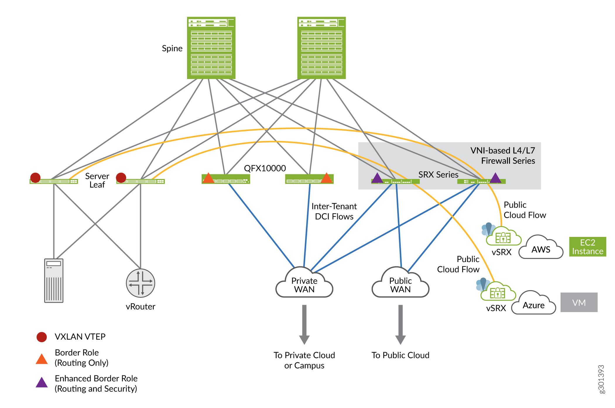 der SRX-Serie
In der Abbildung durchläuft der VXLAN-Datenverkehr vom Leaf-1-Gerät die Firewalls der SRX-Serie, die als EBLs fungieren. In diesem Anwendungsfall wird die Firewall der SRX-Serie an der Grenze platziert, d. h. am Ein- und Ausgangspunkt des Campus oder Datencenters, um eine Stateful Inspection für die VXLAN-gekapselten Pakete zu gewährleisten, die den Campus durchlaufen.
Im Architekturdiagramm können Sie sehen, dass eine Firewall der SRX-Serie zwischen zwei VTEP-Geräten platziert ist (Geräte, die eine VXLAN-Kapselung und -Entkapselung für den Netzwerkverkehr durchführen). Die Firewall der SRX-Serie führt eine Stateful Inspection durch, wenn Sie die Funktion zur Tunnel-Inspektion mit einer geeigneten Sicherheitsrichtlinie aktivieren.
Vorteile
Hinzufügen der Firewall der SRX-Serie in EVPN VXLAN bietet:
- Zusätzliche Sicherheit mit den Funktionen einer Firewall der Enterprise-Klasse im EVPN-VXLAN-Overlay.
- Verbesserte Tunnel-Inspektion für VXLAN-gekapselten Datenverkehr mit Layer-4/Layer-7-Sicherheitsservices.
Beispiel: Konfigurieren von Sicherheitsrichtlinien für die EVPN-VXLAN-Tunnelinspektion
Verwenden Sie dieses Beispiel, um die Sicherheitsrichtlinien zu konfigurieren, die die Überprüfung des EVPN EVPN-VXLAN-Tunnel-Datenverkehrs auf Ihren Firewalls der SRX-Serie ermöglichen.
- Anforderungen
- Bevor Sie beginnen
- Überblick
- Konfiguration
- CLI-Schnellkonfiguration
- Schritt-für-Schritt-Anleitung
- Ergebnisse
- Verifizierung
Anforderungen
In diesem Beispiel werden die folgenden Hardware- und Softwarekomponenten verwendet:
- Eine Firewall der SRX-Serie oder eine virtuelle Firewall vSRX
- Junos OS Version 20.4R1
In diesem Beispiel wird davon ausgegangen, dass Sie bereits über ein EVPN-VXLAN-basiertes Netzwerk verfügen und die Tunnel-Inspektion auf der Firewall der SRX-Serie aktivieren möchten.
Bevor Sie beginnen
- Stellen Sie sicher, dass Sie über eine gültige Lizenz für die Anwendungsidentifikationsfunktion auf Ihrer Firewall der SRX-Serie und ein auf dem Gerät installiertes Anwendungssignaturpaket verfügen.
- Stellen Sie sicher, dass Sie verstehen, wie EVPN und VXLAN funktionieren. Siehe EVPN-VXLAN Campus-Architekturen für detailliertes Verständnis von EVPN-VXLAN
-
In diesem Beispiel wird davon ausgegangen, dass Sie bereits über eine EVPN-VXLAN-basierte Netzwerk-Fabric verfügen und die Tunnel-Inspektion auf der Firewall der SRX-Serie aktivieren möchten. Die Beispielkonfiguration von Leaf- und Spine-Geräten, die in diesem Beispiel verwendet werden, finden Sie unter Vollständige Gerätekonfigurationen.
Überblick
In diesem Beispiel konzentrieren wir uns auf die Konfiguration der Firewall der SRX-Serie, die Teil eines funktionierenden EVPN-VXLAN-Netzwerks ist, das aus zwei DC-Standorten mit jeweils einer IP-Fabric besteht. Die Firewall der SRX-Serie wird in einer DCI-Rolle (Data Center Interconnect) zwischen den beiden DCs platziert. In dieser Konfiguration führt die Firewall der SRX-Serie eine Stateful Inspection des VXLAN-gekapselten Datenverkehrs durch, der zwischen den DCs fließt, wenn Sie die Tunnel-Inspektion aktivieren.
Wir verwenden in diesem Beispiel die in Abbildung 2 gezeigte Topologie.
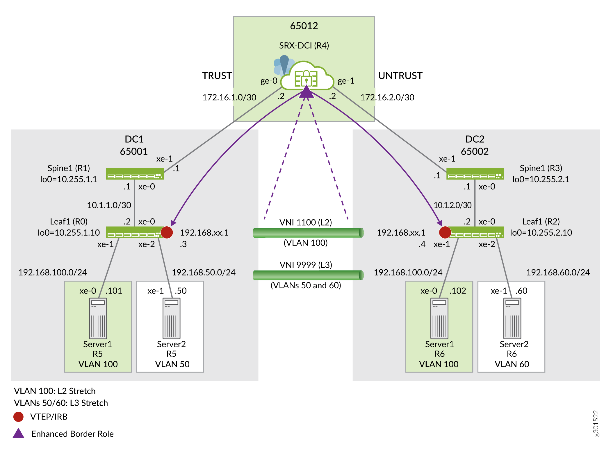
Wie in der Topologie angegeben, überprüft die Firewall der SRX-Serie den in Transit-VLAN gekapselten Datenverkehr vom VXLAN Tunnel Endpoint (VTEP) auf den Leafs sowohl im DC-1- als auch im DC-2-Datencenter. Jedes physische und virtuelle Gerät von Juniper Networks, das als Layer-2- oder Layer-3-VXLAN-Gateway fungiert, kann als VTEP-Gerät für die Durchführung der Kapselung und -Entkapselung fungieren.
Nach Erhalt eines Layer-2- oder Layer-3-Datenpakets von Server 1 fügt der Leaf-1-VTEP den entsprechenden VXLAN-Header hinzu und kapselt das Paket dann mit einem IPv4-Außenheader ein, um das Tunneling des Pakets durch das IPv4-Underlay-Netzwerk zu erleichtern. Der Remote-VTEP auf Leaf 2 entkapselt dann den Datenverkehr und leitet das ursprüngliche Paket an den Zielhost weiter. Mit der Softwareversion 20.4 der Junos-Software sind Firewalls der SRX-Serie in der Lage, eine Tunnel-Inspektion für VXLAN-gekapselten Overlay-Datenverkehr durchzuführen.
In diesem Beispiel erstellen Sie eine Sicherheitsrichtlinie, um die Überprüfung für Datenverkehr zu aktivieren, der in einem VXLAN-Tunnel gekapselt ist. Wir verwenden die in Tabelle 1 beschriebenen Parameter in diesem Beispiel.
| Parameter | Beschreibung | Name des Parameters |
|---|---|---|
| Sicherheits-Richtlinie | Richtlinie zum Erstellen einer Flow-Sitzung, die durch VXLAN-Overlay-Datenverkehr ausgelöst wird. Diese Richtlinie verweist auf die äußere IP-Quell- und Zieladresse. Das heißt, die IP-Adressen der Quell- und Ziel-VTEPs. In diesem Beispiel ist dies die Loopback-Adresse der Leaves. | P1 |
| Richtlinie festgelegt | Richtlinie für die Inspektion des inneren Verkehrs. Diese Richtlinie gilt für den Inhalt des übereinstimmenden VXLAN-Tunnel-Datenverkehrs. | PSET-1 |
| Tunnel-Inspektionsprofil | Gibt Parameter für die Sicherheitsüberprüfung in VXLAN-Tunneln an. | TP-1 |
| Name einer Liste oder eines Bereichs für VXLAN-Netzwerkkennungen (VNI) | Wird verwendet, um eine Liste oder einen Bereich von VXLAN-Tunnel-IDs eindeutig zu identifizieren. | VLAN-100 |
| Name der VXLAN-Tunnel-Kennung. | Wird verwendet, um einen VXLAN-Tunnel in einem Tunnel-Inspektionsprofil symbolisch zu benennen. | VNI-1100 |
Wenn Sie Sicherheitsrichtlinien für die Tunnel-Inspektion auf der Firewall der SRX-Serie konfigurieren, wird das Paket entkapselt, um auf den inneren Header zuzugreifen, wenn ein Paket mit einer Sicherheitsrichtlinie übereinstimmt. Als Nächstes wendet es das Tunnel-Inspektionsprofil an, um zu bestimmen, ob der innere Datenverkehr zulässig ist. Das Sicherheitsgerät verwendet den inneren Paketinhalt und die Parameter des angewendeten Tunnel-Inspektionsprofils, um eine Richtliniensuche durchzuführen und dann eine Stateful Inspection für die innere Sitzung durchzuführen.
So beheben Sie das Problem, ohne das VNI-Setup zu ändern:
- Geben Sie sowohl eingehende als auch ausgehende VRF-IDs in dieselbe VRF-Gruppen-ID ein.
- Verwenden Sie in der Sicherheitsrichtlinie dieselbe Quell- und Ziel-VRF-Gruppen-ID als Übereinstimmungskriterien.
Konfiguration
In diesem Beispiel konfigurieren Sie die folgenden Funktionen auf der Firewall der SRX-Serie:
- Definieren Sie eine vertrauenswürdige und eine nicht vertrauenswürdige Zone, um den gesamten Hostdatenverkehr zuzulassen. Dies unterstützt die BGP-Sitzung zu den Spine-Geräten und ermöglicht SSH usw. aus beiden Zonen (DC).
- Überprüfen Sie den Datenverkehr, der von DC1 nach DC2 fließt, in VNI 1100 (Layer 2 gestreckt für VLAN 100) für alle Hosts im Subnetz 192.168.100.0/24. Ihre Richtlinie sollte Pings zulassen, aber jeden anderen Datenverkehr ablehnen.
- Lassen Sie den gesamten Rückverkehr von DC2 zu DC1 ohne Tunnel-Inspektion zu.
- Lassen Sie allen anderen Underlay- und Overlay-Datenverkehr ohne VXLAN-Tunnel-Inspektion von DC1 zu DC2 zu.
Führen Sie die folgenden Schritte aus, um die Tunnel-Inspektion auf Ihrem Sicherheitsgerät in einer VXLAN-EVPN-Umgebung zu aktivieren:
Vollständige Funktionskonfigurationen für alle in diesem Beispiel verwendeten Geräte werden bereitgestellt. Vollständige Gerätekonfigurationen , um den Leser beim Testen dieses Beispiels zu unterstützen.
Dieses Beispiel konzentriert sich auf die Konfigurationsschritte, die zum Aktivieren und Überprüfen der VXLAN-Tunnel-Inspektionsfunktion erforderlich sind. Es wird davon ausgegangen, dass die Firewall der SRX-Serie mit Schnittstellenadressierung, BGP-Peering und Richtlinien konfiguriert ist, um ihre DCI-Rolle zu unterstützen.
CLI-Schnellkonfiguration
Um dieses Beispiel schnell auf Ihrer Firewall der SRX-Serie zu konfigurieren, kopieren Sie die folgenden Befehle, fügen Sie sie in eine Textdatei ein, entfernen Sie alle Zeilenumbrüche, ändern Sie alle erforderlichen Details, um sie an Ihre Netzwerkkonfiguration anzupassen, kopieren Sie dann die Befehle und fügen Sie sie dann in die CLI auf der Hierarchieebene [edit] ein.
Konfiguration auf Gerät der SRX-Serie
set system host-name r4-dci-ebr
set security address-book global address vtep-untrust 10.255.2.0/24
set security address-book global address vtep-trust 10.255.1.0/24
set security address-book global address vlan100 192.168.100.0/24
set security policies from-zone trust to-zone untrust policy P1 match source-address vtep-trust
set security policies from-zone trust to-zone untrust policy P1 match destination-address vtep-untrust
set security policies from-zone trust to-zone untrust policy P1 match application junos-vxlan
set security policies from-zone trust to-zone untrust policy P1 then permit tunnel-inspection TP-1
set security policies from-zone untrust to-zone trust policy accept-all-dc2 match source-address any
set security policies from-zone untrust to-zone trust policy accept-all-dc2 match destination-address any
set security policies from-zone untrust to-zone trust policy accept-all-dc2 match application any
set security policies from-zone untrust to-zone trust policy accept-all-dc2 then permit
set security policies policy-set PSET-1 policy PSET-1-P1 match source-address vlan100
set security policies policy-set PSET-1 policy PSET-1-P1 match destination-address vlan100
set security policies policy-set PSET-1 policy PSET-1-P1 match application junos-icmp-all
set security policies policy-set PSET-1 policy PSET-1-P1 then permit
set security zones security-zone trust host-inbound-traffic system-services all
set security zones security-zone trust host-inbound-traffic protocols all
set security zones security-zone trust interfaces ge-0/0/0.0
set security zones security-zone untrust host-inbound-traffic system-services all
set security zones security-zone untrust host-inbound-traffic protocols all
set security zones security-zone untrust interfaces ge-0/0/1.0
set security tunnel-inspection inspection-profile TP-1 vxlan VNI-1100 policy-set PSET-1
set security tunnel-inspection inspection-profile TP-1 vxlan VNI-1100 vni VLAN-100
set security tunnel-inspection vni VLAN-100 vni-id 1100
set interfaces ge-0/0/0 description "Link to DC1 Spine 1"
set interfaces ge-0/0/0 mtu 9000
set interfaces ge-0/0/0 unit 0 family inet address 172.16.1.2/30
set interfaces ge-0/0/1 description "Link to DC2 Spine 1"
set interfaces ge-0/0/1 mtu 9000
set interfaces ge-0/0/1 unit 0 family inet address 172.16.2.2/30
Schritt-für-Schritt-Anleitung
- Konfigurieren Sie Sicherheitszonen, Schnittstellen und Adressbücher.
[edit]
user@@r4-dci-ebr# set security zones security-zone trust
user@@r4-dci-ebr# set security zones security-zone untrust
user@@r4-dci-ebr# set interfaces ge-0/0/0 description "Link to DC1 Spine 1"
user@@r4-dci-ebr# set interfaces ge-0/0/0 mtu 9000
user@@r4-dci-ebr# set interfaces ge-0/0/0 unit 0 family inet address 172.16.1.2/30
user@@r4-dci-ebr# set interfaces ge-0/0/1 description "Link to DC2 Spine 1"
user@@r4-dci-ebr# set interfaces ge-0/0/1 mtu 9000
user@@r4-dci-ebr# set interfaces ge-0/0/1 unit 0 family inet address 172.16.2.2/30
user@@r4-dci-ebr# set security zones security-zone trust host-inbound-traffic system-services all
user@@r4-dci-ebr# set security zones security-zone trust host-inbound-traffic protocols all
user@@r4-dci-ebr# set security zones security-zone trust interfaces ge-0/0/0.0
user@@r4-dci-ebr# set security zones security-zone untrust host-inbound-traffic system-services all
user@@r4-dci-ebr# set security zones security-zone untrust host-inbound-traffic protocols all
user@@r4-dci-ebr# set security zones security-zone untrust interfaces ge-0/0/1.0
user@@r4-dci-ebr# set security address-book global address vtep-untrust 10.255.2.0/24
user@@r4-dci-ebr# set security address-book global address vtep-trust 10.255.1.0/24
user@@r4-dci-ebr# set security address-book global address vlan100 192.168.100.0/24
-
Definieren Sie das Tunnel-Inspektionsprofil. Sie können einen Bereich oder eine Liste von VNIs angeben, die überprüft werden sollen.
[edit]
user@@r4-dci-ebr# set security tunnel-inspection vni VLAN-100 vni-id 1100
user@@r4-dci-ebr# set security tunnel-inspection inspection-profile TP-1 vxlan VNI-1100 vni VLAN-100
user@@r4-dci-ebr# set security tunnel-inspection inspection-profile TP-1 vxlan VNI-1100 policy-set PSET-1
In diesem Beispiel wird nur ein VNI benötigt, sodass das
Das Tunnel-Inspektionsprofil ist sowohl mit der NNI-Liste/dem VNI-Bereich als auch mit der zugehörigen Richtlinie verknüpft, die auf den VXLAN-Tunnel mit entsprechenden VNIs angewendet werden soll.vni-idSchlüsselwort anstelle dervni-rangeOption verwendet wird. - Erstellen Sie eine Sicherheitsrichtlinie, die mit der äußeren Sitzung übereinstimmt.
[edit]
user@@r4-dci-ebr# set security policies from-zone trust to-zone untrust policy P1 match source-address vtep-trust
user@@r4-dci-ebr# set security policies from-zone trust to-zone untrust policy P1 match destination-address vtep-untrust
user@@r4-dci-ebr# set security policies from-zone trust to-zone untrust policy P1 match application junos-vxlan
user@@r4-dci-ebr# set security policies from-zone trust to-zone untrust policy P1 then permit tunnel-inspection TP-1
TP-1Sie im vorherigen Schritt definiert haben. In diesem Beispiel besteht das Ziel darin, VXLAN-Tunnel zu untersuchen, die von DC1 ausgehen und in DC2 enden. Daher ist eine zweite Richtlinie, die beim zurückgegebenen Datenverkehr abgeglichen werden muss (mit DC2, Leaf 1, dem Quell-VTEP), nicht erforderlich. -
Erstellen Sie den Richtliniensatz für die innere Sitzung.
[edit]
user@@r4-dci-ebr# set security policies policy-set PSET-1 policy PSET-1-P1 match source-address vlan100
user@@r4-dci-ebr# set security policies policy-set PSET-1 policy PSET-1-P1 match destination-address vlan100
user@@r4-dci-ebr# set security policies policy-set PSET-1 policy PSET-1-P1 match application junos-icmp-all
user@@r4-dci-ebr# set security policies policy-set PSET-1 policy PSET-1-P1 then permit
Diese Richtlinie führt eine Sicherheitsüberprüfung für die Nutzlast des übereinstimmenden VXLAN-Datenverkehrs durch. In diesem Beispiel ist dies der Datenverkehr, der von Server 1 auf VLAN 100 in DC1 an Server 1 in DC2 gesendet wird. Durch Angeben der
junos-icmp-allÜbereinstimmungsbedingung stellen Sie sicher, dass sowohl Ping-Anforderungen als auch Antworten von Server 1 Ion DC1 an Server 1 in DC2 übergeben werden können. Wenn Sie angebenjunos-icmp-ping, sind nur Pings zulässig, die von DC1 stammen.Denken Sie daran, dass in diesem Beispiel nur Ping zulässig ist, um das Testen der resultierenden Funktionalität zu erleichtern. Sie können den
application anygesamten Datenverkehr zulassen oder die Übereinstimmungskriterien so ändern, dass sie Ihren spezifischen Sicherheitsanforderungen entsprechen. -
Definieren Sie die Richtlinien, die erforderlich sind, um jeglichen anderen Datenverkehr zwischen den Datencentern ohne Tunnel-Prüfung zu akzeptieren.
[edit]
user@@r4-dci-ebr# set security policies from-zone trust to-zone untrust policy accept-rest match source-address any
user@@r4-dci-ebr# set security policies from-zone trust to-zone untrust policy accept-rest match destination-address any
user@@r4-dci-ebr# set security policies from-zone trust to-zone untrust policy accept-rest match application any
user@@r4-dci-ebr# set security policies from-zone trust to-zone untrust policy accept-rest then permit
user@@r4-dci-ebr# set security policies from-zone untrust to-zone trust policy accept-all-dc2 match source-address any
user@@r4-dci-ebr# set security policies from-zone untrust to-zone trust policy accept-all-dc2 match destination-address any
user@@r4-dci-ebr# set security policies from-zone untrust to-zone trust policy accept-all-dc2 match application any
user@@r4-dci-ebr# set security policies from-zone untrust to-zone trust policy accept-all-dc2 then permit
Ergebnisse
Bestätigen Sie im Konfigurationsmodus Ihre Konfiguration durch Eingabe des show security Befehls. Wenn die Ausgabe nicht die beabsichtigte Konfiguration anzeigt, wiederholen Sie die Konfigurationsanweisungen in diesem Beispiel, um sie zu korrigieren.
[edit]
user@host# show security
address-book {
    global {
        address vtep-untrust 10.255.2.0/24;
        address vtep-trust 10.255.1.0/24;
        address vlan100 192.168.100.0/24;
    }
}
policies {
    from-zone trust to-zone untrust {
        policy P1 {
            match {
                source-address vtep-trust;
                destination-address vtep-untrust;
                application junos-vxlan;
            }
            then {
                permit {
                    tunnel-inspection {
                        TP-1;
                    }
                }
            }
        }
        policy accept-rest {
            match {
                source-address any;
                destination-address any;
                application any;
            }
            then {
                permit;
            }
        }
    }
    from-zone untrust to-zone trust {
        policy accept-all-dc2 {
            match {
                source-address any;
                destination-address any;
                application any;
            }
            then {
                permit;
            }
        }
    }
    policy-set PSET-1 {
        policy PSET-1-P1 {
            match {
                source-address vlan100;
                destination-address vlan100;
                application junos-icmp-all;
            }
            then {
                permit;
            }
        }
    }
}
zones {
    security-zone trust {
        host-inbound-traffic {
            system-services {
                all;
            }
            protocols {
                all;
            }
        }
        interfaces {
            ge-0/0/0.0;
        }
    }
    security-zone untrust {
        host-inbound-traffic {
            system-services {
                all;
            }
            protocols {
                all;
            }
        }
        interfaces {
            ge-0/0/1.0;
        }
    }
}
tunnel-inspection {
    inspection-profile TP-1 {
        vxlan VNI-1100 {
            policy-set PSET-1;
            vni VLAN-100;
        }
    }
    vni VLAN-100 {
        vni-id 1100;
    }
}
Wenn Sie mit der Konfiguration der Funktion auf Ihrem Gerät fertig sind, rufen Sie den Konfigurationsmodus auf commit .
Verifizierung
Zu diesem Zeitpunkt sollten Sie Ping-Datenverkehr zwischen Server 1 in DC1 und Server 1 in DC2 generieren. Die Pings sollten erfolgreich sein. Lassen Sie diesen Testdatenverkehr im Hintergrund laufen, während Sie die Überprüfungsaufgaben ausführen.
r5-dc1_server1> ping 192.168.100.102
PING 192.168.100.102 (192.168.100.102): 56 data bytes
64 bytes from 192.168.100.102: icmp_seq=0 ttl=64 time=565.451 ms
64 bytes from 192.168.100.102: icmp_seq=1 ttl=64 time=541.035 ms
64 bytes from 192.168.100.102: icmp_seq=2 ttl=64 time=651.420 ms
64 bytes from 192.168.100.102: icmp_seq=3 ttl=64 time=303.533 ms
. . .
- Überprüfen Sie die Details der inneren Richtlinien
- Überprüfen des Datenverkehrs bei der Tunnelinspektion
- Überprüfen Sie das Tunnelinspektionsprofil und den VNI
- Überprüfen der Sicherheits-Flows
- Bestätigen Sie, dass SSH blockiert ist.
Überprüfen Sie die Details der inneren Richtlinien
Purpose
Überprüfen Sie die Details der Richtlinie, die für die innere Sitzung angewendet wurde.
Action
Geben Sie im Betriebsmodus den show security policies policy-set PSET-1 Befehl ein.
From zone: PSET-1, To zone: PSET-1
  Policy: PSET-1-P1, State: enabled, Index: 7, Scope Policy: 0, Sequence number: 1, Log Profile ID: 0
    From zones: any
    To zones: any
    Source vrf group: any
    Destination vrf group: any
    Source addresses: vlan100
    Destination addresses: vlan100
    Applications: junos-icmp-all
    Source identity feeds: any
    Destination identity feeds: any
    Action: permit
Überprüfen des Datenverkehrs bei der Tunnelinspektion
Purpose
Zeigen Sie die Datenverkehrsdetails der Tunnel-Inspektion an.
Action
Geben Sie im Betriebsmodus den show security flow tunnel-inspection statistics Befehl ein.
  Flow Tunnel-inspection statistics:
  Tunnel-inspection type VXLAN:
    overlay session active:             4
    overlay session create:           289
    overlay session close:            285
    underlay session active:            3
    underlay session create:           31
    underlay session close:            28
    input packets:          607
    input bytes:         171835
    output packets:         418
    output bytes:         75627
    bypass packets:           0
    bypass bytes:             0
Überprüfen Sie das Tunnelinspektionsprofil und den VNI
Purpose
Zeigen Sie das Tunnel-Inspektionsprofil und die VNI-Details an.
Action
Geben Sie im Betriebsmodus den show security tunnel-inspection profiles Befehl ein.
Logical system: root-logical-system
  Profile count: 1
  Profile: TP-1
    Type: VXLAN
    Vxlan count: 1
    Vxlan name: VXT-1
    VNI count: 1
      VNI:VNI-1
      Policy set: PSET-1
      Inspection level: 1
Geben Sie im Betriebsmodus den show security tunnel-inspection vnis Befehl ein.
Logical system: root-logical-system
  VNI count: 2
  VNI name: VLAN-100
      VNI id count: 1
      [1100 - 1100]
  VNI name: VNI-1
      VNI id count: 1
      [1100 - 1100]
Überprüfen der Sicherheits-Flows
Purpose
Zeigen Sie die VXLAN-Sicherheitsflussinformationen auf der SRX an, um zu bestätigen, dass die VXLAN-Tunnel-Inspektion funktioniert.
Action
Geben Sie im Betriebsmodus den show security flow session vxlan-vni 1100 Befehl ein.
Session ID: 3811, Policy name: PSET-1-P1/7, State: Stand-alone, Timeout: 2, Valid
  In: 192.168.100.101/47883 --> 192.168.100.102/82;icmp, Conn Tag: 0xfcd, If: ge-0/0/0.0, Pkts: 1, Bytes: 84,
  Type: VXLAN, VNI: 1100, Tunnel Session ID: 2193
  Out: 192.168.100.102/82 --> 192.168.100.101/47883;icmp, Conn Tag: 0xfcd, If: ge-0/0/1.0, Pkts: 0, Bytes: 0,
  Type: VXLAN, VNI: 0, Tunnel Session ID: 0

Session ID: 3812, Policy name: PSET-1-P1/7, State: Stand-alone, Timeout: 2, Valid
  In: 192.168.100.101/47883 --> 192.168.100.102/83;icmp, Conn Tag: 0xfcd, If: ge-0/0/0.0, Pkts: 1, Bytes: 84,
  Type: VXLAN, VNI: 1100, Tunnel Session ID: 2193
  Out: 192.168.100.102/83 --> 192.168.100.101/47883;icmp, Conn Tag: 0xfcd, If: ge-0/0/1.0, Pkts: 0, Bytes: 0,
  Type: VXLAN, VNI: 0, Tunnel Session ID: 0

. . .
Bestätigen Sie, dass SSH blockiert ist.
Purpose
Versuchen Sie, eine SSH-Sitzung zwischen Server 1 in DC1 und Server 2 in DC2 einzurichten. Basierend auf der Richtlinie, die nur Ping-Datenverkehr zulässt, sollte diese Sitzung an der SRX blockiert werden.
Action
Geben Sie im Betriebsmodus den show security flow session vxlan-vni 1100 Befehl ein.
r5-dc1_server1> ssh 192.168.100.102
ssh: connect to host 192.168.100.102 port 22: Operation timed out
r5_dc1_server1>
Konfiguration für Inspektion auf Zonenebene, IDP, Content-Sicherheit und erweiterte Anti-Malware für die Tunnelinspektion
Verwenden Sie diesen Schritt, wenn Sie eine Überprüfung auf Zonenebene konfigurieren und Layer-7-Services wie IDP, Juniper ATP, Content Sicherheit und erweiterte Anti-Malware auf den Tunnel-Datenverkehr anwenden möchten. Diese Funktion wird ab Junos OS Version 21.1R1 unterstützt.
In diesem Beispiel werden die folgenden Hardware- und Softwarekomponenten verwendet:
- Eine Firewall der SRX-Serie oder eine virtuelle Firewall vSRX
- Junos OS Version 21.1R1
Wir verwenden dieselbe Konfiguration für Adressbücher, Sicherheitszonen, Schnittstellen, Tunnel-Inspektionsprofil und Sicherheitsrichtlinie für die äußere Sitzung, die in Konfiguration erstellt wurde
Bei diesem Schritt wird davon ausgegangen, dass Sie Ihre Firewall der SRX-Serie bei Juniper ATP registriert haben. Weitere Informationen zur Registrierung Ihrer Firewall der SRX-Serie finden Sie im Hilfeartikel Registrieren einer Firewall der SRX-Serie mit dem Juniper ATP-Cloud-Webportal.
In dieser Konfiguration erstellen Sie einen Richtliniensatz für die innere Sitzung und wenden IDP, Content Sicherheit und erweiterte Antischadsoftware auf den Tunnel-Datenverkehr an.
- CLI-Schnellkonfiguration
- Erstellen einer Inspektion auf Zonenebene für die Tunnelinspektion
- Erstellen Sie IDP, Content-Sicherheit und erweiterte Anti-Malware für die Tunnelinspektion
- Ergebnisse
CLI-Schnellkonfiguration
Um dieses Beispiel schnell auf Ihrer Firewall der SRX-Serie zu konfigurieren, kopieren Sie die folgenden Befehle, fügen Sie sie in eine Textdatei ein, entfernen Sie alle Zeilenumbrüche, ändern Sie alle erforderlichen Details, um sie an Ihre Netzwerkkonfiguration anzupassen, kopieren Sie dann die Befehle und fügen Sie sie dann in die CLI auf der Hierarchieebene [edit] ein.
Konfiguration auf Gerät der SRX-Serie
set system host-name r4-dci-ebr
set security address-book global address vtep-untrust 10.255.2.0/24
set security address-book global address vtep-trust 10.255.1.0/24
set security address-book global address vlan100 192.168.100.0/24
set security policies from-zone trust to-zone untrust policy P1 match source-address vtep-trust
set security policies from-zone trust to-zone untrust policy P1 match destination-address vtep-untrust
set security policies from-zone trust to-zone untrust policy P1 match application junos-vxlan
set security policies from-zone trust to-zone untrust policy P1 then permit tunnel-inspection TP-1
set security policies from-zone untrust to-zone trust policy accept-all-dc2 match source-address any
set security policies from-zone untrust to-zone trust policy accept-all-dc2 match destination-address any
set security policies from-zone untrust to-zone trust policy accept-all-dc2 match application any
set security policies from-zone untrust to-zone trust policy accept-all-dc2 then permit
set security policies policy-set PSET-1 policy PSET-1-P1 match source-address vlan100
set security policies policy-set PSET-1 policy PSET-1-P1 match destination-address vlan100
set security policies policy-set PSET-1 policy PSET-1-P1 match application junos-icmp-all
set security policies policy-set PSET-1 policy PSET-1-P1 match dynamic-application any
set security policies policy-set PSET-1 policy PSET-1-P1 match url-category any
set security policies policy-set PSET-1 policy PSET-1-P1 match from-zone trust
set security policies policy-set PSET-1 policy PSET-1-P1 match to-zone untrust
set security policies policy-set PSET-1 policy PSET-1-P1 then permit
set security policies policy-set PSET-1 policy PSET-1-P1 then permit
set security zones security-zone trust host-inbound-traffic system-services all
set security zones security-zone trust host-inbound-traffic protocols all
set security zones security-zone trust interfaces ge-0/0/0.0
set security zones security-zone untrust host-inbound-traffic system-services all
set security zones security-zone untrust host-inbound-traffic protocols all
set security zones security-zone untrust interfaces ge-0/0/1.0
set security tunnel-inspection inspection-profile TP-1 vxlan VNI-1100 policy-set PSET-1
set security tunnel-inspection inspection-profile TP-1 vxlan VNI-1100 vni VLAN-100
set security tunnel-inspection vni VLAN-100 vni-id 1100
set interfaces ge-0/0/0 description "Link to DC1 Spine 1"
set interfaces ge-0/0/0 mtu 9000
set interfaces ge-0/0/0 unit 0 family inet address 172.16.1.2/30
set interfaces ge-0/0/1 description "Link to DC2 Spine 1"
set interfaces ge-0/0/1 mtu 9000
set interfaces ge-0/0/1 unit 0 family inet address 172.16.2.2/30
Erstellen einer Inspektion auf Zonenebene für die Tunnelinspektion
Sie können eine Richtliniensteuerung auf Zonenebene für die EVPN-VXLAN-Tunnel-Inspektion für den inneren Datenverkehr hinzufügen. Diese Richtlinie führt eine Sicherheitsüberprüfung für die Nutzlast des übereinstimmenden VXLAN-Datenverkehrs durch. Im folgenden Schritt geben Sie from-zone und to-zone für den Datenverkehr an.
-
[edit]
user@r4-dci-ebr# set security policies policy-set PSET-1 policy PSET-1-P1 match source-address vlan100
user@r4-dci-ebr# set security policies policy-set PSET-1 policy PSET-1-P1 match destination-address vlan100
user@r4-dci-ebr# set security policies policy-set PSET-1 policy PSET-1-P1 match application any
user@r4-dci-ebr# set security policies policy-set PSET-1 policy PSET-1-P1 match dynamic-application any
user@r4-dci-ebr# set security policies policy-set PSET-1 policy PSET-1-P1 match url-category any
user@r4-dci-ebr# set security policies policy-set PSET-1 policy PSET-1-P1 match from-zone trust
user@r4-dci-ebr# set security policies policy-set PSET-1 policy PSET-1-P1 match to-zone untrust
user@r4-dci-ebr# set security policies policy-set PSET-1 policy PSET-1-P1 then permit
Erstellen Sie IDP, Content-Sicherheit und erweiterte Anti-Malware für die Tunnelinspektion
Sie können Sicherheitsdienste wie IDP, erweiterte Aniti-Malware, Content Sicherheit, SSL-Proxy für das EVPN-VXLAN Tunnel Überprüfung für den internen Datenverkehr hinzufügen. Diese Richtlinie führt eine Sicherheitsüberprüfung für die Nutzlast des übereinstimmenden VXLAN-Datenverkehrs durch.
Im folgenden Schritt aktivieren Sie Dienste wie IDP, Content Sicherheit, SSL Proxy, Security-Intelligence und Advanced Anti-Malware Services, indem Sie sie in einer Sicherheitsrichtlinien-Zulassungsaktion angeben, wenn der Datenverkehr mit der Richtlinienregel übereinstimmt.
-
[edit]
user@r4-dci-ebr# set security policies policy-set PSET-1 policy PSET-1-P1 match source-address vlan100
user@r4-dci-ebr# set security policies policy-set PSET-1 policy PSET-1-P1 match destination-address vlan100
user@r4-dci-ebr# set security policies policy-set PSET-1 policy PSET-1-P1 match application any
user@r4-dci-ebr# set security policies policy-set PSET-1 policy PSET-1-P1 then permit application-services ssl-proxy profile-name ssl-inspect-profile-1
user@r4-dci-ebr# set security policies policy-set PSET-1 policy PSET-1-P1 then permit application-services security-intelligence-policy secintel1
user@r4-dci-ebr# set security policies policy-set PSET-1 policy PSET-1-P1 then permit application-services advanced-anti-malware-policy P3
user@r4-dci-ebr# set security policies policy-set PSET-1 policy PSET-1-P1 then permit application-services idp-policy idp123
user@r4-dci-ebr# set security policies policy-set PSET-1 policy PSET-1-P1 then permit application-services utm-policy P1
Die folgenden Schritte zeigen Konfigurationsausschnitte für Content Sicherheit, IDP und erweiterte Anti-Malware-Richtlinien auf einen Blick.
-
Konfigurieren Sie erweiterte Antischadsoftwarerichtlinien.
[edit]
user@r4-dci-ebr# set services advanced-anti-malware policy P3 http inspection-profile scripts
user@r4-dci-ebr# set services advanced-anti-malware policy P3 http action block
user@r4-dci-ebr# set services advanced-anti-malware policy P3 http notification log
user@r4-dci-ebr# set services advanced-anti-malware policy P3 http client-notify message "AAMW Blocked!"
user@r4-dci-ebr# set services advanced-anti-malware policy P3 verdict-threshold recommended
user@r4-dci-ebr# set services advanced-anti-malware policy P3 fallback-options action permit
user@r4-dci-ebr# set services advanced-anti-malware policy P3 fallback-options notification log
-
Konfigurieren Sie das Security Intelligence-Profil.
[edit]
user@r4-dci-ebr# set services security-intelligence url https://cloudfeeds.argonqa.junipersecurity.net/api/manifest.xml
user@r4-dci-ebr# set services security-intelligence authentication tls-profile aamw-ssl
user@r4-dci-ebr# set services security-intelligence profile cc_profile category CC
user@r4-dci-ebr# set services security-intelligence profile cc_profile rule cc_rule match threat-level 1
user@r4-dci-ebr# set services security-intelligence profile cc_profile rule cc_rule match threat-level 2
user@r4-dci-ebr# set services security-intelligence profile cc_profile rule cc_rule match threat-level 4
user@r4-dci-ebr# set services security-intelligence profile cc_profile rule cc_rule match threat-level 5
user@r4-dci-ebr# set services security-intelligence profile cc_profile rule cc_rule match threat-level 6
user@r4-dci-ebr# set services security-intelligence profile cc_profile rule cc_rule match threat-level 7
user@r4-dci-ebr# set services security-intelligence profile cc_profile rule cc_rule match threat-level 8
user@r4-dci-ebr# set services security-intelligence profile cc_profile rule cc_rule match threat-level 9
user@r4-dci-ebr# set services security-intelligence profile cc_profile rule cc_rule match threat-level 10
user@r4-dci-ebr# set services security-intelligence profile cc_profile rule cc_rule then action block close
user@r4-dci-ebr# set services security-intelligence profile cc_profile rule cc_rule then log
user@r4-dci-ebr# set services security-intelligence profile ih_profile category Infected-Hosts
user@r4-dci-ebr# set services security-intelligence profile ih_profile rule ih_rule match threat-level 7
user@r4-dci-ebr# set services security-intelligence profile ih_profile rule ih_rule match threat-level 8
user@r4-dci-ebr# set services security-intelligence profile ih_profile rule ih_rule match threat-level 9
user@r4-dci-ebr# set services security-intelligence profile ih_profile rule ih_rule match threat-level 10
user@r4-dci-ebr# set services security-intelligence profile ih_profile rule ih_rule then action block close http message "Blocked!"
user@r4-dci-ebr# set services security-intelligence profile ih_profile rule ih_rule then log
user@r4-dci-ebr# set services security-intelligence policy secintel1 CC cc_profile
user@r4-dci-ebr# set services security-intelligence policy secintel1 Infected-Hosts ih_profile
-
Konfigurieren Sie die IDP-Richtlinie.
[edit]
user@r4-dci-ebr# set security idp idp-policy idp123 rulebase-ips rule rule1 match application junos-icmp-all
user@r4-dci-ebr# set security idp idp-policy idp123 rulebase-ips rule rule1 then action no-action
-
Konfigurieren der Content Sicherheit-Richtlinie.
[edit]
user@r4-dci-ebr# set security utm default-configuration anti-virus type sophos-engine
user@r4-dci-ebr## set security utm utm-policy P1 anti-virus http-profile junos-sophos-av-defaults
-
Konfigurieren Sie SSL-Profile.
[edit]
user@r4-dci-ebr# set services ssl initiation profile aamw-ssl
user@r4-dci-ebr# set services ssl proxy profile ssl-inspect-profile-1 root-ca VJSA
Ergebnisse
Bestätigen Sie im Konfigurationsmodus Ihre Konfiguration durch Eingabe des show security Befehls. Wenn die Ausgabe nicht die beabsichtigte Konfiguration anzeigt, wiederholen Sie die Konfigurationsanweisungen in diesem Beispiel, um sie zu korrigieren.
[edit]
user@host# show security
address-book {
    global {
        address vtep-untrust 10.255.2.0/24;
        address vtep-trust 10.255.1.0/24;
        address vlan100 192.168.100.0/24;
    }
}
policies {
    from-zone trust to-zone untrust {
        policy P1 {
            match {
                source-address vtep-trust;
                destination-address vtep-untrust;
                application junos-vxlan;
            }
            then {
                permit {
                    tunnel-inspection {
                        TP-1;
                    }
                }
            }
        }
        policy accept-rest {
            match {
                source-address any;
                destination-address any;
                application any;
            }
            then {
                permit;
            }
        }
    }
    from-zone untrust to-zone trust {
        policy accept-all-dc2 {
            match {
                source-address any;
                destination-address any;
                application any;
            }
            then {
                permit;
            }
        }
    }
    policy-set PSET-1 {
        policy PSET-1-P1 {
            match {
                source-address vlan100;
                destination-address vlan100;
                application junos-icmp-all;
                dynamic-application any;
                url-category any;
                from-zone trust;
                to-zone untrust;
            }
           then {
            permit {
                application-services {
                    idp-policy idp123;
                    ssl-proxy {
                        profile-name ssl-inspect-profile-1;
                    }
                    utm-policy P1;
                    security-intelligence-policy secintel1;
                    advanced-anti-malware-policy P3;
                }
            }
        }
            }
        }
    }
}
zones {
    security-zone trust {
        host-inbound-traffic {
            system-services {
                all;
            }
            protocols {
                all;
            }
        }
        interfaces {
            ge-0/0/0.0;
        }
    }
    security-zone untrust {
        host-inbound-traffic {
            system-services {
                all;
            }
            protocols {
                all;
            }
        }
        interfaces {
            ge-0/0/1.0;
        }
    }
}
tunnel-inspection {
    inspection-profile TP-1 {
        vxlan VNI-1100 {
            policy-set PSET-1;
            vni VLAN-100;
        }
    }
    vni VLAN-100 {
        vni-id 1100;
    }
}
[edit]
user@host# show services
application-identification;
ssl {
    initiation {
        profile aamw-ssl;
    }
    proxy {
        profile ssl-inspect-profile-1 {
            root-ca VJSA;
        }
    }
}
advanced-anti-malware {
    policy P3 {
        http {
            inspection-profile scripts;
            action block;
            client-notify {
                message "AAMW Blocked!";
            }
            notification {
                log;
            }
        }
        verdict-threshold recommended;
        fallback-options {
            action permit;
            notification {
                log;
            }
        }
    }
}
security-intelligence {
    url https://cloudfeeds.argonqa.junipersecurity.net/api/manifest.xml;
    authentication {
        tls-profile aamw-ssl;
    }
    profile cc_profile {
        category CC;
        rule cc_rule {
            match {
                threat-level [ 1 2 4 5 6 7 8 9 10 ];
            }
            then {
                action {
                    block {
                        close;
                    }
                }
                log;
            }
        }
    }
    profile ih_profile {
        category Infected-Hosts;
        rule ih_rule {
            match {
                threat-level [ 7 8 9 10 ];
            }
            then {
                action {
                    block {
                        close {
                            http {
                                message "Blocked!";
                            }
                        }
                    }
                }
                log;
            }
        }
    }
    policy secintel1 {
        CC {
            cc_profile;
        }
        Infected-Hosts {
            ih_profile;
        }
    }
}
Wenn Sie mit der Konfiguration der Funktion auf Ihrem Gerät fertig sind, rufen Sie den Konfigurationsmodus auf commit .
Vollständige Gerätekonfigurationen
Beziehen Sie sich auf diese Konfigurationen, um den Kontext dieses Beispiels besser zu verstehen oder neu zu erstellen. Sie umfassen die vollständigen ERB-basierten EVPN-VXLAN-Konfigurationen für die Switches der QFX-Serie, die die DC-Fabrics bilden, sowie den Endzustand der Firewall der SRX-Serie für die grundlegenden und erweiterten Beispiele für die Inspektion von VXLAN-Tunneln.
Die bereitgestellten Konfigurationen zeigen keine Benutzeranmeldung, Systemprotokollierung oder verwaltungsbezogene Konfiguration an, da diese je nach Standort variiert und nicht mit der VXLAN-Tunnel-Inspektionsfunktion zusammenhängt.
Weitere Details und Beispiele für die Konfiguration von EVPN-VXLAN finden Sie im Beispiel für die Netzwerkkonfiguration unter Konfigurieren einer EVPN-VXLAN-Fabric für ein Campusnetzwerk mit ERB.
- Konfiguration auf Leaf-1-Gerät
- Konfiguration auf Spine 1-Gerät
- Konfiguration auf Leaf 2-Gerät
- Konfiguration auf Spine 2-Gerät
- Grundlegende Konfiguration der Tunnelinspektion auf einem Gerät der SRX-Serie
- Konfiguration der Tunnelinspektion auf Geräten der SRX-Serie mit Layer 7-Sicherheitsservices
Konfiguration auf Leaf-1-Gerät
set system host-name r0_dc1_leaf1
set interfaces xe-0/0/0 mtu 9000
set interfaces xe-0/0/0 unit 0 family inet address 10.1.1.2/30
set interfaces xe-0/0/1 unit 0 family ethernet-switching vlan members v100
set interfaces xe-0/0/2 unit 0 family ethernet-switching vlan members v50
set interfaces irb unit 50 virtual-gateway-accept-data
set interfaces irb unit 50 family inet address 192.168.50.3/24 preferred
set interfaces irb unit 50 family inet address 192.168.50.3/24 virtual-gateway-address 192.168.50.1
set interfaces irb unit 100 virtual-gateway-accept-data
set interfaces irb unit 100 family inet address 192.168.100.3/24 preferred
set interfaces irb unit 100 family inet address 192.168.100.3/24 virtual-gateway-address 192.168.100.1
set interfaces lo0 unit 0 family inet address 10.255.1.10/32
set interfaces lo0 unit 1 family inet address 10.255.10.10/32
set forwarding-options vxlan-routing next-hop 32768
set forwarding-options vxlan-routing overlay-ecmp
set policy-options policy-statement ECMP-POLICY then load-balance per-packet
set policy-options policy-statement FROM_Lo0 term 10 from interface lo0.0
set policy-options policy-statement FROM_Lo0 term 10 then accept
set policy-options policy-statement FROM_Lo0 term 20 then reject
set policy-options policy-statement OVERLAY_IMPORT term 5 from community comm_pod1
set policy-options policy-statement OVERLAY_IMPORT term 5 then accept
set policy-options policy-statement OVERLAY_IMPORT term 10 from community comm_pod2
set policy-options policy-statement OVERLAY_IMPORT term 10 then accept
set policy-options policy-statement OVERLAY_IMPORT term 20 from community shared_100_fm_pod2
set policy-options policy-statement OVERLAY_IMPORT term 20 from community shared_100_fm_pod1
set policy-options policy-statement OVERLAY_IMPORT term 20 then accept
set policy-options policy-statement T5_EXPORT term fm_direct from protocol direct
set policy-options policy-statement T5_EXPORT term fm_direct then accept
set policy-options policy-statement T5_EXPORT term fm_static from protocol static
set policy-options policy-statement T5_EXPORT term fm_static then accept
set policy-options policy-statement T5_EXPORT term fm_v4_host from protocol evpn
set policy-options policy-statement T5_EXPORT term fm_v4_host from route-filter 0.0.0.0/0 prefix-length-range /32-/32
set policy-options policy-statement T5_EXPORT term fm_v4_host then accept
set policy-options policy-statement VRF1_T5_RT_EXPORT term t1 then community add target_t5_pod1
set policy-options policy-statement VRF1_T5_RT_EXPORT term t1 then accept
set policy-options policy-statement VRF1_T5_RT_IMPORT term t1 from community target_t5_pod1
set policy-options policy-statement VRF1_T5_RT_IMPORT term t1 then accept
set policy-options policy-statement VRF1_T5_RT_IMPORT term t2 from community target_t5_pod2
set policy-options policy-statement VRF1_T5_RT_IMPORT term t2 then accept
set policy-options community comm_pod1 members target:65001:1
set policy-options community comm_pod2 members target:65002:2
set policy-options community shared_100_fm_pod1 members target:65001:100
set policy-options community shared_100_fm_pod2 members target:65002:100
set policy-options community target_t5_pod1 members target:65001:9999
set policy-options community target_t5_pod2 members target:65002:9999
set routing-instances TENANT_1_VRF routing-options multipath
set routing-instances TENANT_1_VRF protocols evpn ip-prefix-routes advertise direct-nexthop
set routing-instances TENANT_1_VRF protocols evpn ip-prefix-routes encapsulation vxlan
set routing-instances TENANT_1_VRF protocols evpn ip-prefix-routes vni 9999
set routing-instances TENANT_1_VRF protocols evpn ip-prefix-routes export T5_EXPORT
set routing-instances TENANT_1_VRF instance-type vrf
set routing-instances TENANT_1_VRF interface irb.50
set routing-instances TENANT_1_VRF interface irb.100
set routing-instances TENANT_1_VRF interface lo0.1
set routing-instances TENANT_1_VRF route-distinguisher 10.255.1.10:9999
set routing-instances TENANT_1_VRF vrf-import VRF1_T5_RT_IMPORT
set routing-instances TENANT_1_VRF vrf-export VRF1_T5_RT_EXPORT
set routing-instances TENANT_1_VRF vrf-table-label
set routing-options router-id 10.255.1.10
set routing-options autonomous-system 65001
set routing-options forwarding-table export ECMP-POLICY
set routing-options forwarding-table ecmp-fast-reroute
set routing-options forwarding-table chained-composite-next-hop ingress evpn
set protocols bgp group EVPN_FABRIC type internal
set protocols bgp group EVPN_FABRIC local-address 10.255.1.10
set protocols bgp group EVPN_FABRIC family evpn signaling
set protocols bgp group EVPN_FABRIC multipath
set protocols bgp group EVPN_FABRIC bfd-liveness-detection minimum-interval 1000
set protocols bgp group EVPN_FABRIC bfd-liveness-detection multiplier 3
set protocols bgp group EVPN_FABRIC neighbor 10.255.1.1
set protocols bgp group UNDERLAY type external
set protocols bgp group UNDERLAY family inet unicast
set protocols bgp group UNDERLAY export FROM_Lo0
set protocols bgp group UNDERLAY local-as 65510
set protocols bgp group UNDERLAY multipath multiple-as
set protocols bgp group UNDERLAY bfd-liveness-detection minimum-interval 350
set protocols bgp group UNDERLAY bfd-liveness-detection multiplier 3
set protocols bgp group UNDERLAY neighbor 10.1.1.1 peer-as 65511
set protocols evpn encapsulation vxlan
set protocols evpn default-gateway no-gateway-community
set protocols evpn vni-options vni 150 vrf-target target:65001:150
set protocols evpn vni-options vni 1100 vrf-target target:65001:100
set protocols evpn extended-vni-list 1100
set protocols evpn extended-vni-list 150
set protocols lldp interface all
set switch-options vtep-source-interface lo0.0
set switch-options route-distinguisher 10.255.1.10:1
set switch-options vrf-import OVERLAY_IMPORT
set switch-options vrf-target target:65001:1
set vlans v100 vlan-id 100
set vlans v100 l3-interface irb.100
set vlans v100 vxlan vni 1100
set vlans v50 vlan-id 50
set vlans v50 l3-interface irb.50
set vlans v50 vxlan vni 150
Konfiguration auf Spine 1-Gerät
set system host-name r1_dc1_spine11
set interfaces xe-0/0/0 mtu 9000
set interfaces xe-0/0/0 unit 0 family inet address 10.1.1.1/30
set interfaces xe-0/0/1 mtu 9000
set interfaces xe-0/0/1 unit 0 family inet address 172.16.1.1/30
set interfaces lo0 unit 0 family inet address 10.255.1.1/32
set policy-options policy-statement ECMP-POLICY then load-balance per-packet
set policy-options policy-statement FROM_Lo0 term 10 from interface lo0.0
set policy-options policy-statement FROM_Lo0 term 10 then accept
set policy-options policy-statement FROM_Lo0 term 20 then reject
set policy-options policy-statement UNDERLAY-EXPORT term LOOPBACK from route-filter 10.255.0.0/16 orlonger
set policy-options policy-statement UNDERLAY-EXPORT term LOOPBACK from route-filter 10.1.0.0/16 orlonger
set policy-options policy-statement UNDERLAY-EXPORT term LOOPBACK then accept
set policy-options policy-statement UNDERLAY-EXPORT term DEFAULT then reject
set policy-options policy-statement UNDERLAY-IMPORT term LOOPBACK from route-filter 10.255.0.0/16 orlonger
set policy-options policy-statement UNDERLAY-IMPORT term LOOPBACK from route-filter 10.1.0.0/16 orlonger
set policy-options policy-statement UNDERLAY-IMPORT term LOOPBACK then accept
set policy-options policy-statement UNDERLAY-IMPORT term DEFAULT then reject
set routing-options autonomous-system 65001
set routing-options forwarding-table export ECMP-POLICY
set routing-options forwarding-table ecmp-fast-reroute
set protocols bgp group EVPN_FABRIC type internal
set protocols bgp group EVPN_FABRIC local-address 10.255.1.1
set protocols bgp group EVPN_FABRIC family evpn signaling
set protocols bgp group EVPN_FABRIC cluster 10.255.1.1
set protocols bgp group EVPN_FABRIC multipath
set protocols bgp group EVPN_FABRIC bfd-liveness-detection minimum-interval 1000
set protocols bgp group EVPN_FABRIC bfd-liveness-detection multiplier 3
set protocols bgp group EVPN_FABRIC neighbor 10.255.1.10
set protocols bgp group EVPN_FABRIC vpn-apply-export
set protocols bgp group UNDERLAY type external
set protocols bgp group UNDERLAY import UNDERLAY-IMPORT
set protocols bgp group UNDERLAY family inet unicast
set protocols bgp group UNDERLAY export UNDERLAY-EXPORT
set protocols bgp group UNDERLAY local-as 65511
set protocols bgp group UNDERLAY multipath multiple-as
set protocols bgp group UNDERLAY bfd-liveness-detection minimum-interval 350
set protocols bgp group UNDERLAY bfd-liveness-detection multiplier 3
set protocols bgp group UNDERLAY neighbor 10.1.1.2 peer-as 65510
set protocols bgp group UNDERLAY neighbor 172.16.1.2 peer-as 65012
set protocols bgp group OVERLAY_INTERDC type external
set protocols bgp group OVERLAY_INTERDC multihop no-nexthop-change
set protocols bgp group OVERLAY_INTERDC local-address 10.255.1.1
set protocols bgp group OVERLAY_INTERDC family evpn signaling
set protocols bgp group OVERLAY_INTERDC multipath multiple-as
set protocols bgp group OVERLAY_INTERDC neighbor 10.255.2.1 peer-as 65002
set protocols lldp interface all
Konfiguration auf Leaf 2-Gerät
set system host-name r2_dc2_leaf1
set interfaces xe-0/0/0 mtu 9000
set interfaces xe-0/0/0 unit 0 family inet address 10.1.2.2/30
set interfaces xe-0/0/1 unit 0 family ethernet-switching vlan members v100
set interfaces xe-0/0/2 unit 0 family ethernet-switching vlan members v60
set interfaces irb unit 60 virtual-gateway-accept-data
set interfaces irb unit 60 family inet address 192.168.60.3/24 preferred
set interfaces irb unit 60 family inet address 192.168.60.3/24 virtual-gateway-address 192.168.60.1
set interfaces irb unit 100 virtual-gateway-accept-data
set interfaces irb unit 100 family inet address 192.168.100.4/24 preferred
set interfaces irb unit 100 family inet address 192.168.100.4/24 virtual-gateway-address 192.168.100.1
set interfaces lo0 unit 0 family inet address 10.255.2.10/32
set interfaces lo0 unit 1 family inet address 10.255.20.10/32
set forwarding-options vxlan-routing next-hop 32768
set forwarding-options vxlan-routing overlay-ecmp
set policy-options policy-statement ECMP-POLICY then load-balance per-packet
set policy-options policy-statement FROM_Lo0 term 10 from interface lo0.0
set policy-options policy-statement FROM_Lo0 term 10 then accept
set policy-options policy-statement FROM_Lo0 term 20 then reject
set policy-options policy-statement OVERLAY_IMPORT term 5 from community comm_pod1
set policy-options policy-statement OVERLAY_IMPORT term 5 then accept
set policy-options policy-statement OVERLAY_IMPORT term 10 from community comm_pod2
set policy-options policy-statement OVERLAY_IMPORT term 10 then accept
set policy-options policy-statement OVERLAY_IMPORT term 20 from community shared_100_fm_pod2
set policy-options policy-statement OVERLAY_IMPORT term 20 from community shared_100_fm_pod1
set policy-options policy-statement OVERLAY_IMPORT term 20 then accept
set policy-options policy-statement T5_EXPORT term fm_direct from protocol direct
set policy-options policy-statement T5_EXPORT term fm_direct then accept
set policy-options policy-statement T5_EXPORT term fm_static from protocol static
set policy-options policy-statement T5_EXPORT term fm_static then accept
set policy-options policy-statement T5_EXPORT term fm_v4_host from protocol evpn
set policy-options policy-statement T5_EXPORT term fm_v4_host from route-filter 0.0.0.0/0 prefix-length-range /32-/32
set policy-options policy-statement T5_EXPORT term fm_v4_host then accept
set policy-options policy-statement VRF1_T5_RT_EXPORT term t1 then community add target_t5_pod1
set policy-options policy-statement VRF1_T5_RT_EXPORT term t1 then accept
set policy-options policy-statement VRF1_T5_RT_IMPORT term t1 from community target_t5_pod1
set policy-options policy-statement VRF1_T5_RT_IMPORT term t1 then accept
set policy-options policy-statement VRF1_T5_RT_IMPORT term t2 from community target_t5_pod2
set policy-options policy-statement VRF1_T5_RT_IMPORT term t2 then accept
set policy-options community comm_pod1 members target:65001:1
set policy-options community comm_pod2 members target:65002:2
set policy-options community shared_100_fm_pod1 members target:65001:100
set policy-options community shared_100_fm_pod2 members target:65002:100
set policy-options community target_t5_pod1 members target:65001:9999
set policy-options community target_t5_pod2 members target:65002:9999
set routing-instances TENANT_1_VRF routing-options multipath
set routing-instances TENANT_1_VRF protocols evpn ip-prefix-routes advertise direct-nexthop
set routing-instances TENANT_1_VRF protocols evpn ip-prefix-routes encapsulation vxlan
set routing-instances TENANT_1_VRF protocols evpn ip-prefix-routes vni 9999
set routing-instances TENANT_1_VRF protocols evpn ip-prefix-routes export T5_EXPORT
set routing-instances TENANT_1_VRF instance-type vrf
set routing-instances TENANT_1_VRF interface irb.60
set routing-instances TENANT_1_VRF interface irb.100
set routing-instances TENANT_1_VRF interface lo0.1
set routing-instances TENANT_1_VRF route-distinguisher 10.255.1.2:9999
set routing-instances TENANT_1_VRF vrf-import VRF1_T5_RT_IMPORT
set routing-instances TENANT_1_VRF vrf-export VRF1_T5_RT_EXPORT
set routing-instances TENANT_1_VRF vrf-table-label
set routing-options router-id 10.255.2.10
set routing-options autonomous-system 65002
set routing-options forwarding-table export ECMP-POLICY
set routing-options forwarding-table ecmp-fast-reroute
set routing-options forwarding-table chained-composite-next-hop ingress evpn
set protocols bgp group EVPN_FABRIC type internal
set protocols bgp group EVPN_FABRIC local-address 10.255.2.10
set protocols bgp group EVPN_FABRIC family evpn signaling
set protocols bgp group EVPN_FABRIC multipath
set protocols bgp group EVPN_FABRIC bfd-liveness-detection minimum-interval 1000
set protocols bgp group EVPN_FABRIC bfd-liveness-detection multiplier 3
set protocols bgp group EVPN_FABRIC neighbor 10.255.2.1
set protocols bgp group UNDERLAY type external
set protocols bgp group UNDERLAY family inet unicast
set protocols bgp group UNDERLAY export FROM_Lo0
set protocols bgp group UNDERLAY local-as 65522
set protocols bgp group UNDERLAY multipath multiple-as
set protocols bgp group UNDERLAY bfd-liveness-detection minimum-interval 350
set protocols bgp group UNDERLAY bfd-liveness-detection multiplier 3
set protocols bgp group UNDERLAY neighbor 10.1.2.1 peer-as 65523
set protocols evpn encapsulation vxlan
set protocols evpn default-gateway no-gateway-community
set protocols evpn vni-options vni 160 vrf-target target:65002:160
set protocols evpn vni-options vni 1100 vrf-target target:65002:100
set protocols evpn extended-vni-list 1100
set protocols evpn extended-vni-list 160
set protocols lldp interface all
set switch-options vtep-source-interface lo0.0
set switch-options route-distinguisher 10.255.2.10:1
set switch-options vrf-import OVERLAY_IMPORT
set switch-options vrf-target target:65002:1
set vlans v100 vlan-id 100
set vlans v100 l3-interface irb.100
set vlans v100 vxlan vni 1100
set vlans v60 vlan-id 60
set vlans v60 l3-interface irb.60
set vlans v60 vxlan vni 160
Konfiguration auf Spine 2-Gerät
set system host-name r3_dc2_spine1
set interfaces xe-0/0/0 mtu 9000
set interfaces xe-0/0/0 unit 0 family inet address 10.1.2.1/30
set interfaces xe-0/0/1 mtu 9000
set interfaces xe-0/0/1 unit 0 family inet address 172.16.2.1/30
set interfaces lo0 unit 0 family inet address 10.255.2.1/32
set policy-options policy-statement ECMP-POLICY then load-balance per-packet
set policy-options policy-statement FROM_Lo0 term 10 from interface lo0.0
set policy-options policy-statement FROM_Lo0 term 10 then accept
set policy-options policy-statement FROM_Lo0 term 20 then reject
set policy-options policy-statement UNDERLAY-EXPORT term LOOPBACK from route-filter 10.255.0.0/16 orlonger
set policy-options policy-statement UNDERLAY-EXPORT term LOOPBACK from route-filter 10.1.0.0/16 orlonger
set policy-options policy-statement UNDERLAY-EXPORT term LOOPBACK then accept
set policy-options policy-statement UNDERLAY-EXPORT term DEFAULT then reject
set policy-options policy-statement UNDERLAY-IMPORT term LOOPBACK from route-filter 10.255.0.0/16 orlonger
set policy-options policy-statement UNDERLAY-IMPORT term LOOPBACK from route-filter 10.1.0.0/16 orlonger
set policy-options policy-statement UNDERLAY-IMPORT term LOOPBACK then accept
set policy-options policy-statement UNDERLAY-IMPORT term DEFAULT then reject
set routing-options autonomous-system 65002
set routing-options forwarding-table export ECMP-POLICY
set routing-options forwarding-table ecmp-fast-reroute
set protocols bgp group EVPN_FABRIC type internal
set protocols bgp group EVPN_FABRIC local-address 10.255.2.1
set protocols bgp group EVPN_FABRIC family evpn signaling
set protocols bgp group EVPN_FABRIC cluster 10.255.2.1
set protocols bgp group EVPN_FABRIC multipath
set protocols bgp group EVPN_FABRIC bfd-liveness-detection minimum-interval 1000
set protocols bgp group EVPN_FABRIC bfd-liveness-detection multiplier 3
set protocols bgp group EVPN_FABRIC neighbor 10.255.2.10
set protocols bgp group EVPN_FABRIC vpn-apply-export
set protocols bgp group UNDERLAY type external
set protocols bgp group UNDERLAY import UNDERLAY-IMPORT
set protocols bgp group UNDERLAY family inet unicast
set protocols bgp group UNDERLAY export UNDERLAY-EXPORT
set protocols bgp group UNDERLAY local-as 65523
set protocols bgp group UNDERLAY multipath multiple-as
set protocols bgp group UNDERLAY bfd-liveness-detection minimum-interval 350
set protocols bgp group UNDERLAY bfd-liveness-detection multiplier 3
set protocols bgp group UNDERLAY neighbor 10.1.2.2 peer-as 65522
set protocols bgp group UNDERLAY neighbor 172.16.2.2 peer-as 65012
set protocols bgp group OVERLAY_INTERDC type external
set protocols bgp group OVERLAY_INTERDC multihop no-nexthop-change
set protocols bgp group OVERLAY_INTERDC local-address 10.255.2.1
set protocols bgp group OVERLAY_INTERDC family evpn signaling
set protocols bgp group OVERLAY_INTERDC multipath multiple-as
set protocols bgp group OVERLAY_INTERDC neighbor 10.255.1.1 peer-as 65001
set protocols lldp interface all
Grundlegende Konfiguration der Tunnelinspektion auf einem Gerät der SRX-Serie
set system host-name r4-dci-ebr
set security address-book global address vtep-untrust 10.255.2.0/24
set security address-book global address vtep-trust 10.255.1.0/24
set security address-book global address vlan100 192.168.100.0/24
set security policies from-zone trust to-zone untrust policy P1 match source-address vtep-trust
set security policies from-zone trust to-zone untrust policy P1 match destination-address vtep-untrust
set security policies from-zone trust to-zone untrust policy P1 match application junos-vxlan
set security policies from-zone trust to-zone untrust policy P1 then permit tunnel-inspection TP-1
set security policies from-zone trust to-zone untrust policy accept-rest match source-address any
set security policies from-zone trust to-zone untrust policy accept-rest match destination-address any
set security policies from-zone trust to-zone untrust policy accept-rest match application any
set security policies from-zone trust to-zone untrust policy accept-rest then permit
set security policies from-zone untrust to-zone trust policy accept-return match source-address any
set security policies from-zone untrust to-zone trust policy accept-return match destination-address any
set security policies from-zone untrust to-zone trust policy accept-return match application any
set security policies from-zone untrust to-zone trust policy accept-return then permit
set security policies policy-set PSET-1 policy PSET-1-P1 match source-address vlan100
set security policies policy-set PSET-1 policy PSET-1-P1 match destination-address vlan100
set security policies policy-set PSET-1 policy PSET-1-P1 match application junos-icmp-all
set security policies policy-set PSET-1 policy PSET-1-P1 then permit
set security zones security-zone trust host-inbound-traffic system-services all
set security zones security-zone trust host-inbound-traffic protocols all
set security zones security-zone trust interfaces ge-0/0/0.0
set security zones security-zone untrust host-inbound-traffic system-services all
set security zones security-zone untrust host-inbound-traffic protocols all
set security zones security-zone untrust interfaces ge-0/0/1.0
set security tunnel-inspection inspection-profile TP-1 vxlan VNI-1100 policy-set PSET-1
set security tunnel-inspection inspection-profile TP-1 vxlan VNI-1100 vni VLAN-100
set security tunnel-inspection vni VLAN-100 vni-id 1100
set interfaces ge-0/0/0 description "Link to DC2 Spine 1"
set interfaces ge-0/0/0 mtu 9000
set interfaces ge-0/0/0 unit 0 family inet address 172.16.1.2/30
set interfaces ge-0/0/1 mtu 9000
set interfaces ge-0/0/1 unit 0 family inet address 172.16.2.2/30
set policy-options policy-statement ECMP-POLICY then load-balance per-packet
set policy-options policy-statement dci term 1 from protocol direct
set policy-options policy-statement dci term 1 then accept
set protocols bgp group UNDERLAY export dci
set protocols bgp group UNDERLAY multipath multiple-as
set protocols bgp group UNDERLAY bfd-liveness-detection minimum-interval 350
set protocols bgp group UNDERLAY bfd-liveness-detection multiplier 3
set protocols bgp group UNDERLAY neighbor 172.16.1.1 peer-as 65511
set protocols bgp group UNDERLAY neighbor 172.16.2.1 peer-as 65523
set routing-options autonomous-system 65012
set routing-options forwarding-table export ECMP-POLICY
Konfiguration der Tunnelinspektion auf Geräten der SRX-Serie mit Layer 7-Sicherheitsservices
set system host-name r4-dci-ebrset services application-identification
set services ssl initiation profile aamw-ssl
set services ssl proxy profile ssl-inspect-profile-1 root-ca VJSA
set services advanced-anti-malware policy P3 http inspection-profile scripts
set services advanced-anti-malware policy P3 http action block
set services advanced-anti-malware policy P3 http client-notify message "AAMW Blocked!"
set services advanced-anti-malware policy P3 http notification log
set services advanced-anti-malware policy P3 verdict-threshold recommended
set services advanced-anti-malware policy P3 fallback-options action permit
set services advanced-anti-malware policy P3 fallback-options notification log
set services security-intelligence url https://cloudfeeds.argonqa.junipersecurity.net/api/manifest.xml
set services security-intelligence authentication tls-profile aamw-ssl
set services security-intelligence profile cc_profile category CC
set services security-intelligence profile cc_profile rule cc_rule match threat-level 1
set services security-intelligence profile cc_profile rule cc_rule match threat-level 2
set services security-intelligence profile cc_profile rule cc_rule match threat-level 4
set services security-intelligence profile cc_profile rule cc_rule match threat-level 5
set services security-intelligence profile cc_profile rule cc_rule match threat-level 6
set services security-intelligence profile cc_profile rule cc_rule match threat-level 7
set services security-intelligence profile cc_profile rule cc_rule match threat-level 8
set services security-intelligence profile cc_profile rule cc_rule match threat-level 9
set services security-intelligence profile cc_profile rule cc_rule match threat-level 10
set services security-intelligence profile cc_profile rule cc_rule then action block close
set services security-intelligence profile cc_profile rule cc_rule then log
set services security-intelligence profile ih_profile category Infected-Hosts
set services security-intelligence profile ih_profile rule ih_rule match threat-level 7
set services security-intelligence profile ih_profile rule ih_rule match threat-level 8
set services security-intelligence profile ih_profile rule ih_rule match threat-level 9
set services security-intelligence profile ih_profile rule ih_rule match threat-level 10
set services security-intelligence profile ih_profile rule ih_rule then action block close http message "Blocked!"
set services security-intelligence profile ih_profile rule ih_rule then log
set services security-intelligence policy secintel1 CC cc_profile
set services security-intelligence policy secintel1 Infected-Hosts ih_profile
set security pki ca-profile aamw-ca ca-identity deviceCA
set security pki ca-profile aamw-ca enrollment url http://ca.junipersecurity.net:8080/ejbca/publicweb/apply/scep/SRX/pkiclient.exe
set security pki ca-profile aamw-ca revocation-check disable
set security pki ca-profile aamw-ca revocation-check crl url http://va.junipersecurity.net/ca/deviceCA.crl
set security pki ca-profile aamw-secintel-ca ca-identity JUNIPER
set security pki ca-profile aamw-secintel-ca revocation-check crl url http://va.junipersecurity.net/ca/current.crl
set security pki ca-profile aamw-cloud-ca ca-identity JUNIPER_CLOUD
set security pki ca-profile aamw-cloud-ca revocation-check crl url http://va.junipersecurity.net/ca/cloudCA.crl
set security idp idp-policy idp123 rulebase-ips rule rule1 match application junos-icmp-all
set security idp idp-policy idp123 rulebase-ips rule rule1 then action no-action
set security address-book global address vtep-untrust 10.255.2.0/24
set security address-book global address vtep-trust 10.255.1.0/24
set security address-book global address vlan100 192.168.100.0/24
set security utm default-configuration anti-virus type sophos-engine
set security utm utm-policy P1 anti-virus http-profile junos-sophos-av-defaults
set security policies from-zone trust to-zone untrust policy P1 match source-address vtep-trust
set security policies from-zone trust to-zone untrust policy P1 match destination-address vtep-untrust
set security policies from-zone trust to-zone untrust policy P1 match application junos-vxlan
set security policies from-zone trust to-zone untrust policy P1 then permit tunnel-inspection TP-1
set security policies from-zone trust to-zone untrust policy accept-rest match source-address any
set security policies from-zone trust to-zone untrust policy accept-rest match destination-address any
set security policies from-zone trust to-zone untrust policy accept-rest match application any
set security policies from-zone trust to-zone untrust policy accept-rest then permit
set security policies from-zone untrust to-zone trust policy accept-return match source-address any
set security policies from-zone untrust to-zone trust policy accept-return match destination-address any
set security policies from-zone untrust to-zone trust policy accept-return match application any
set security policies from-zone untrust to-zone trust policy accept-return then permit
set security policies policy-set PSET-1 policy PSET-1-P1 match source-address vlan100
set security policies policy-set PSET-1 policy PSET-1-P1 match destination-address vlan100
set security policies policy-set PSET-1 policy PSET-1-P1 match application any
set security policies policy-set PSET-1 policy PSET-1-P1 match dynamic-application any
set security policies policy-set PSET-1 policy PSET-1-P1 match url-category any
set security policies policy-set PSET-1 policy PSET-1-P1 match from-zone trust
set security policies policy-set PSET-1 policy PSET-1-P1 match to-zone untrust
set security policies policy-set PSET-1 policy PSET-1-P1 then permit application-services idp-policy idp123
set security policies policy-set PSET-1 policy PSET-1-P1 then permit application-services ssl-proxy profile-name ssl-inspect-profile-1
set security policies policy-set PSET-1 policy PSET-1-P1 then permit application-services utm-policy P1
set security policies policy-set PSET-1 policy PSET-1-P1 then permit application-services security-intelligence-policy secintel1
set security policies policy-set PSET-1 policy PSET-1-P1 then permit application-services advanced-anti-malware-policy P3
set security zones security-zone trust host-inbound-traffic system-services all
set security zones security-zone trust host-inbound-traffic protocols all
set security zones security-zone trust interfaces ge-0/0/0.0
set security zones security-zone untrust host-inbound-traffic system-services all
set security zones security-zone untrust host-inbound-traffic protocols all
set security zones security-zone untrust interfaces ge-0/0/1.0
set security tunnel-inspection inspection-profile TP-1 vxlan VNI-1100 policy-set PSET-1
set security tunnel-inspection inspection-profile TP-1 vxlan VNI-1100 vni VLAN-100
set security tunnel-inspection vni VLAN-100 vni-id 1100
set interfaces ge-0/0/0 description "Link to DC2 Spine 1"
set interfaces ge-0/0/0 mtu 9000
set interfaces ge-0/0/0 unit 0 family inet address 172.16.1.2/30
set interfaces ge-0/0/1 mtu 9000
set interfaces ge-0/0/1 unit 0 family inet address 172.16.2.2/30
set policy-options policy-statement ECMP-POLICY then load-balance per-packet
set policy-options policy-statement dci term 1 from protocol direct
set policy-options policy-statement dci term 1 then accept
set protocols bgp group UNDERLAY export dci
set protocols bgp group UNDERLAY multipath multiple-as
set protocols bgp group UNDERLAY bfd-liveness-detection minimum-interval 350
set protocols bgp group UNDERLAY bfd-liveness-detection multiplier 3
set protocols bgp group UNDERLAY neighbor 172.16.1.1 peer-as 65511
set protocols bgp group UNDERLAY neighbor 172.16.2.1 peer-as 65523
set routing-options autonomous-system 65012
set routing-options static route 0.0.0.0/0 next-hop 10.9.159.252
set routing-options forwarding-table export ECMP-POLICY