配置园区交换矩阵 IP Clos
请按照以下步骤设置园区交换矩阵 IP Clos 架构,使瞻博网络 Mist™ 能够提供集成路由和桥接接口。
瞻博网络 园区交换矩阵 提供单一的、基于标准的 EVPN-VXLAN 解决方案,您可以部署在任何园区内。
园区交换矩阵 IP Clos 架构将 VXLAN L2 网关功能推送到接入层。鉴于 VXLAN 隧道终止于接入层,因此这种模式也称为端到端。
园区交换矩阵 IP Clos 架构支持 基于组的策略 (GBP), 使您能够在网络中实现微分段。GBP 选项为您提供了一种实用的方法来创建独立于底层网络拓扑的网络访问策略。在GBP中,将用户组标记与资源组标记进行匹配,为指定用户提供对指定资源的访问权限。
在园区交换矩阵 IP Clos 架构中,Mist 在接入层上配置第 3 层 (L3) 集成路由和桥接 (IRB) 接口。所有接入交换机为每个 L3 子网配置了相同的 IP 地址。在接入层上终止的最终用户的默认网关设置为所有接入层设备共享的 IRB 地址。此部署模型对参与 L3 子网的所有设备使用任播寻址。此部署模型可为广播流量提供较小的波及范围,非常适合东西向流量模式和 IP 组播环境。
有关 IP Clos 架构及其部署的更多详细信息,请参阅使用 Mist Wired Assurance 的园区交换矩阵 IP Clos - 瞻博网络验证设计 (JVD)。
在 2025 年 5 月更新后在 Mist 云中构建的拓扑中,Mist 会自动检测并报告任何 EVPN 环路和重复的 MAC 地址。这些问题会显示在交换机的“洞察”页面上。
-
EVPN 环路检测 — EVPN-VXLAN 轻量级 PE-客户边缘环路检测有助于检测和断开下游叶至服务器或接入端口上的 LAN 以太网环路。此功能可以检测由各种问题引起的环路,例如交换矩阵组件接线错误或第三方交换机未正确连接到交换矩阵。要使此功能正常工作,交换机必须运行 Junos OS 版本 24.4R1 或更高版本。有关更多信息,请参阅 EVPN-VXLAN 轻型叶到服务器环路检测。
-
重复 MAC 地址检测 — 识别并缓解 EVPN 环境中不同接口或设备之间的 MAC 地址移动(MAC 移动性)所引起的问题。虽然预计会有一些 MAC 移动性(例如,当设备实际移动时),但快速变化可能预示着网络环路或配置错误等问题。有关更多信息,请参阅 配置重复 MAC 地址的环路检测。
园区交换矩阵配置最佳实践
- 在交换机模板级别配置 VLAN,并在配置园区交换矩阵时将其导入。模板必须是所有 VLAN 和端口配置文件的单一事实来源,除非交换机或站点级别有特别要求。
- 在接入层,除非明确要求,否则避免使用允许所有 VLAN 的中继端口配置文件。
- 通过园区交换矩阵(而非交换机模板)创建 VRF 和 VRF 网络配置。
- 为每个角色创建端口分配,并根据需要覆盖单个设备上的配置。
- 通过园区交换矩阵工作流程管理 DHCP 中继配置,服务块设备除外。
要配置园区交换矩阵 IP Clos,请执行以下操作:
- 如果要为站点创建园区交换矩阵,请从页面标题旁边的下拉列表中选择站点。如果要为整个组织创建园区交换矩阵,请从下拉列表中选择“整个组织”。
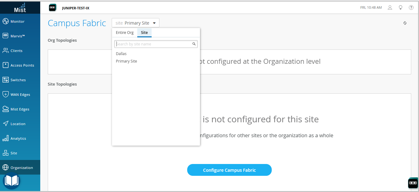 您可以使用组织级园区交换矩阵拓扑来构建包含多栋建筑的园区范围架构。否则,只需使用一组核心、分布式和接入交换机,构建特定于站点的园区交换矩阵。
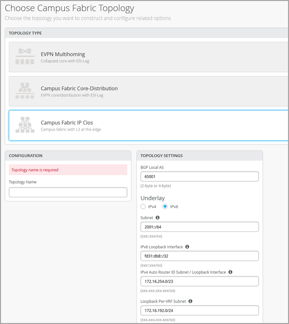
 - 选择拓扑类型:园区交换矩阵、IP Clos。
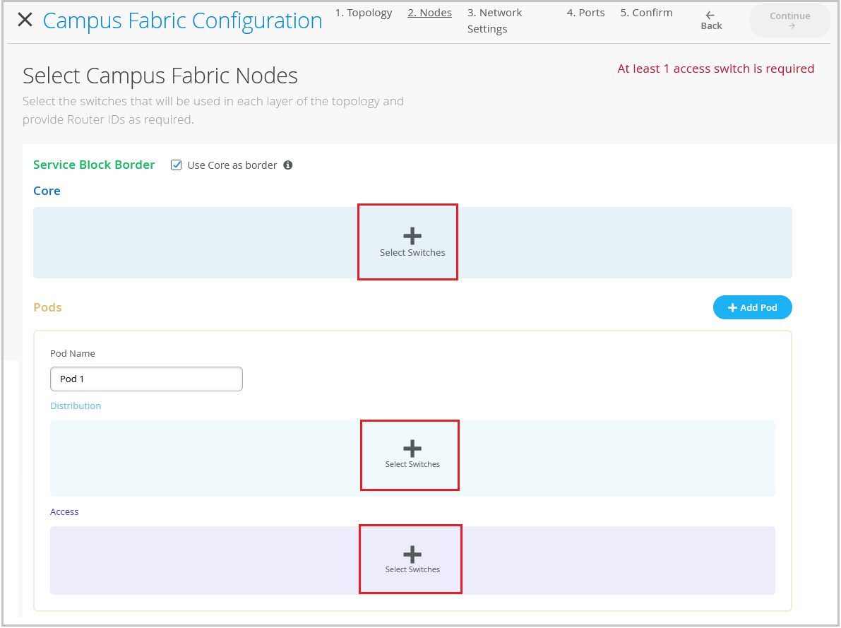
- 单击继续以转到节点选项卡,您可以在其中选择构成园区交换矩阵 IP Clos 部署一部分的设备。
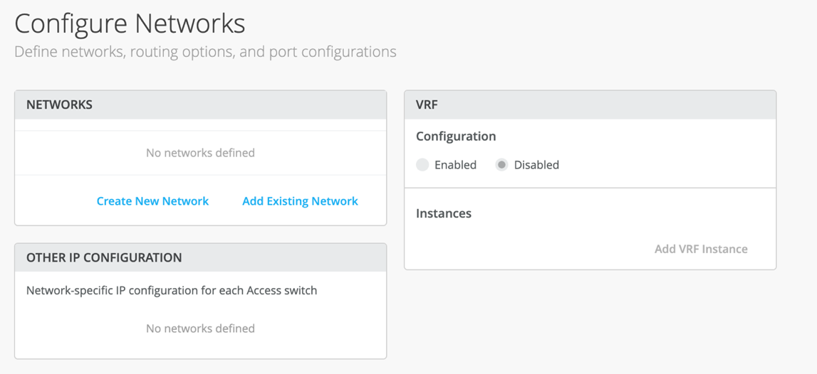
- 配置网络设置,如下所述。
- 单击继续以转到 Ports 选项卡,您可以在其中配置端口并在核心、分布和接入层交换机之间创建连接。
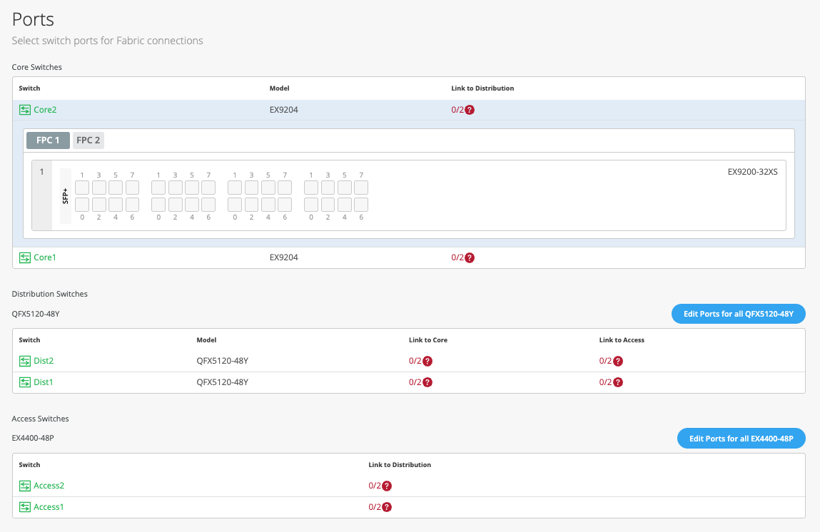
- 如下 所述配置核心层中的交换机端口:
- 在 Core 部分中选择交换机以打开交换机端口面板。
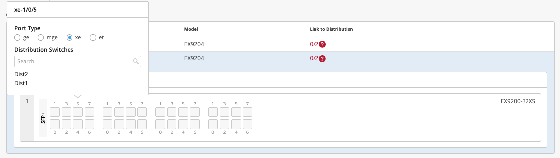
- 从核心交换机的端口面板中,选择要配置的端口。
- 指定端口类型(例如,
ge或xe)。 - 选择链路应终止的分布交换机。您需要配置成为园区交换矩阵一部分的所有端口。
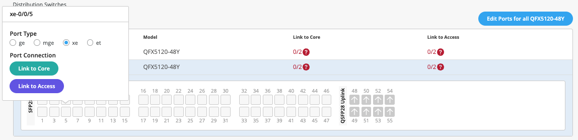
要在分布层中配置交换机端口,请执行以下操作:
要在接入层中配置交换机端口:
- 在 Access 部分中选择交换机以打开交换机端口面板。
- 从交换机的端口面板中,选择要配置的端口。
- 指定端口类型(例如:
ge和xe)。 - 选择链路应终止的分布交换机。您需要配置成为园区交换矩阵一部分的所有端口。
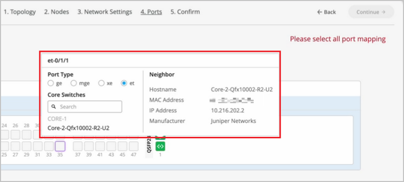
如果要查看特定端口的配置和状态信息,请将鼠标悬停在端口面板 UI 中代表该端口的编号框上。
- 单击关闭园区交换矩阵配置。
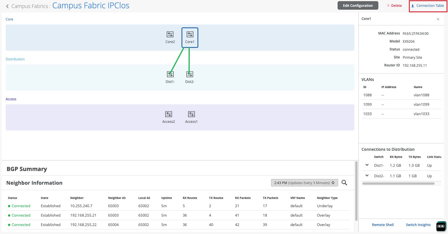
园区交换矩阵建成或正在构建后,您可以下载连接表,该表表示园区交换矩阵的物理布局。您可以使用此表来验证参与物理园区交换矩阵构建的设备的所有交换机互连。单击 连接表 下载(.csv格式)。
For a demo of the configuration steps, watch the following video:
Hello and welcome to this edition of Wired Assurance. My name is Rohan Chadha and I'm a part of the product management team at MIST. Today we're going to talk about deployment of Campus Fabric IP Clos with Wired Assurance.
IP Clos is one of the three topologies supported by Juniper for campus environments. There are different benefits of using IP Clos, it depends on your network environment needs and today we're going to talk about how to deploy it in four steps. I assure you that none of these four steps will involve any CLI configuration and we'll do everything through the UI to quickly build this Campus Fabric in just four steps.
So let's jump right into it and see how to deploy Campus Fabric IP Clos. So before I talk about the building blocks of Campus Fabric IP Clos, I want to give you a heads up that if you are here and you do not know what IP Clos topology is, I recommend you go watch the other video by Rick Bartosik in which he clearly explains the building blocks of IP Clos. Is IP Clos a suitable topology for your environment or should you go with something different like an EVP multi-homing or a Campus Fabric co-distribution? One of the benefits of IP Clos is that you can extend EVPN VXLAN configuration to the edge and what that means is that if you have devices that need EVPN VXLAN or if they're supported, then you can tunnel your devices directly to the access layer.
One other benefit and a great one is GBP. You can use segmentation using tags on the access layer. In this video, we're not going to talk about GBP.
This is purely about the deployment of IP Clos using Wired Assurance. So let's jump right into it and look at the devices we're going to use today for IP Clos. So I'm going to use two QFX 10000 IIs as my core devices and I'm also going to use two QFX 5120 48Y as distribution devices and just for the purposes of this video, I'll be using one access device which is a virtual chassis and virtual chassis is supported by the way for a few platforms like EX4400 in EVPN VXLAN and so we're going to use that virtual chassis as an access switch.
Let's jump right into it. Let's click on organization and under the wire tab, I see campus fabric. So I'll go ahead and click on that.
As I see that in this particular topology, I do not have a campus fabric that's configured for the site. There are two kinds of EVPN configurations that you can build, two kinds of campus fabrics basically, one is a site-based, the other one is an organization-based topology. A site-based topology is where you use a handful of devices, but all of the devices are in a certain site.
In an org-based topology that you can come in and build here, you build topologies on an organization level. So you have one big topology that have different pods from multiple sites. Each pod represents a site and there are core devices that are common to the entire organization and they can be from any site.
But for the purposes of this video to keep things simple, my plan today is to just talk about IP flow on a site-based level. So I'll go back and I'll help you configure a campus fabric IP flow topology. So let's configure campus fabric as usual and as you've seen before, a campus fabric IP flow is option number three that's presented.
At the time of making this video, this topology is still in beta phase. So let's give IP flow topology or configuration name here. So I'll just call it EVPN-IPflow, any name is fine.
There are two options that I have. Do I want to route at distribution or do I want to route at edge? Before I actually get into the details of routing, let's talk about how an IP flow topology looks like or how it could possibly look like for different customers. If you can see my cursor being hovered over this particular little diagram on the left side next to campus fabric IP flow, you'll see that there are three layers and a full mesh.
What that represents is every core device is connected to every distribution device and every distribution device is connected to every access device. And we are traditionally, the L3 is at the edge and edge basically means the access device. However, there is also an option that you can route at distribution.
And what that means is that your gateways, your IRB slash SVI interfaces will reside on the distribution. By default, if you do not make any changes, your IRB slash SVI interfaces will be on your access devices. There are different benefits as I mentioned earlier of using IP flow.
It's primarily used for east-west traffic. But as I said, if you want the details of what IP flow really is, go and watch Rick's video and he explains that in great detail and why you should use it. So once you've selected the topology name and you've made sure that you want to route at the edge, there are a few default settings like overlay and underlay.
These values that you see here are default and you do not have to change it if there isn't a need. At the time of making this video, we are doing a few things. IBGP for overlay and EBGP for underlay.
So 65,000 will be your AS for all the devices that are part of the fabric for overlay and then 65,001 and an incremental sequence. We'll have devices that will be given the AS number going forward. As a user, you do not have to configure any of these changes in the CLI.
The campus fabric feature will take care of everything. The next step is to ensure that this is the loopback prefix that you want. This is slash 24.
This is basically the prefix that we assign to the loopback interfaces for all the devices participating in IP flow. This loopback interface is used to peer with every other device in the overlay. Essentially, every device that is a VTEP for EVPNVX LAN has to peer with the other device for the control plane.
And the next step that you see is the subnet that's required for the underlay IP addressing. This is basically if I have two core devices, two distribution and three IP flow. As a user, you do not have to do any manual IP addressing.
And that's the best part about this feature. Campus fabric will take care of all of the IP addressing. Just provide us a subnet and we'll take care of that.
So let's click continue and move on to the next step. This next step includes selecting campus fabric nodes. As you can see, the step one is selecting a service block border.
So what exactly is a service block? Well, if you are someone who wants to keep your spines, your core devices lean spines, meaning you do not want your core devices to connect to the router, the firewall, or you do not want to use any services connected to the core, such as DHCP, DNS, etc. You can have a separate service block. And in that service block, you can have one to two border switches and you can make all of that connectivity in the service block.
However, this is not a requirement. This is an added feature wherein if you want to have a service block, you can do that. For the purposes of this video and to make things simple, I will be using the core as the border device, meaning that any services or any sort of WAN or firewall connectivity will be on the core device.
So as you see, I get this validation error that says that at least one distribution switch is required. So what this means is that having the core layer is not mandatory. And what that means is that you can have a smaller IP cloud design.
If you're someone who is interested in IP cloud because you want GBP or you want your access points or your other devices are VXLAN capable and you want to form a tunnel, but you want to keep the topology small, you can skip the core layer and have just distribution and access layer. But if all of those requirements are there, but you still would want to have a bigger topology, have a core layer, click on the core devices and select a few switches. So I'm going to select core one and core two.
As I mentioned earlier, for the core layer, for distribution, I'm going to be selecting distribution one and distribution two. As you can see, with just a click of a button, I have this nice little pop-up that gives me the inventory of the site and also tells me which devices are suitable for every layer. The last step is to select the access switches.
I'm just going to be using just one access switch for the purposes of this video. Once you've ensured that you've selected these devices, you can always, before going on to the next step, you have to ensure that you select the router ID and you've selected the access switches. And ensure that they are connected.
And one thing that I'd like to mention here is before we proceed is you can always come back and expand your topology horizontally. And what that means is that as your network needs grow, you can always come in and add access switches and you can add distribution switches to expand your topology. So let's hit continue and go to the next step.
At this step, you will be configuring networks. Networks are basically your VLANs slash bridge domains. You can either create a new network or you can add an existing network.
I'll go ahead and create a new network. And in this case, I will be calling the network EVPNVLAN10. This is just a name.
Do a VLAN ID and I'll go ahead and create a subnet along with a virtual gateway. You can always come and add an existing network as well. And what that means is that if you have networks that you configured on a site level, under site switch configuration, if you configure a VLAN slash network there, it will be propagated to all the devices on a certain site.
So if this particular site has other VLANs, you can always come in and inherit those. You do not have to manually configure a VLAN again. And that's the best part about this.
So I'll go ahead and I'll select these two VLANs. What you can also do is you can import a few VLANs from a certain template. If you have a few templates that you built in the past, however, those templates are either not being used or even if they are being used, you can always inherit a few VLANs from those particular templates.
So I'll go ahead and select this. There is only one VLAN that's part of this particular template. I'll go ahead and select that as well.
And so I'm being told that VLAN 130 doesn't have a subnet. So I'll go ahead and assign a subnet. So at the time of making this video, we are doing a centrally routed and bridged topology.
And what that means is that even though I'm routing at the access, we're still using a virtual gateway. There is also another way that I'm not going to talk about this video, but it is there, which is you can do any cast. What that means is that if you have multiple access switches, every VLAN will have the same IP address on all the devices.
We can talk about that in another video, but to keep things simple, I'll just do what's being shown here and every VLAN will have a virtual gateway. This particular virtual gateway will reside on all the access switches. However, since we have only one access switch in this case, that will be the case.
So the second step is to use VRF configuration, which is basically you can segregate your networks using VRFs. What that means is that if you're someone who wants more security between bridge domains, you want to keep the routing tables separate. You can use virtual routing and forwarding.
You very simply use click on add a VRF instance, give it a name and just assign a VLAN. To keep the configuration simple, I will use only one VLAN for a VRF and I'll keep the rest in the default routing instance. However, there is no limit to how many VLANs you can add to a routing instance.
Let's click continue and let's go to the last step. The last and final step is the selection of ports, wherein you'll be telling us how these devices are connected to each other and how we should be doing the mapping in the backend. So while I go ahead and do the connection for all these devices, sit tight and I'll be fast forwarding this video and get back to you soon.
So I've selected all these ports and I have told Campus Fabric how to connect quota distribution and then distribution to access. As you can see, this is a virtual chassis and it's very well supported. So now that we've selected it and all the requirements are complete and we see some green lights here, let's go ahead and hit continue and just confirm that everything that you wanted to do is straightforward.
So if I click on any device, I'll see the VLANs and the corresponding names. I do not see any IP addresses here, of course, because the IP addresses exist at the access layer. So I can see that VLAN 10 has this particular IP assigned to it and similarly other VLANs as well.
I can always verify my connections, the distribution as well at this layer. So what I also see is I see a little blob here that says remote shell. Before hitting continue and applying changes, you can always click on the remote shell and you can always, rather than logging out of band or logging in out of band or having an SSH connection, we provide you this option where you can verify anything that you'd like.
You want to verify that your connections are the way they look or if you're running a brownfield environment, what that means is if you have an existing Campus Fabric, before you hit apply changes and you want to ensure that none of your configurations are overwritten, if you're moving from an existing manually CLI-configured Campus Fabric to a MIST-configured Campus Fabric, this is the place for you. Hit remote shell, ensure that this is everything that you wanted and then go and hit apply changes. So I'll hit apply changes.
I'm being asked if everything is okay and I'll hit confirm. So at this point, my EVPN IP cloud topology is complete. All the configurations will be pushed at this point.
All of my devices that were a part of the EVPN configuration that I used in the Campus Fabric are being managed as I can see. And what that basically means is that as soon as I hit confirm on Campus Fabric, all of the configuration will be pushed right away. It will be configured.
It probably takes a few seconds for Junos to commit and then a few seconds to a few minutes for BGP, underlay and overlay to come up and form tunnels between all of these devices from core to distribution and then to access. So you may ask, how do I know what configuration has been pushed? I want to ensure that everything that I wanted on the device is there and we have an answer for you. So you can always come in here, click on utilities, and look at download Junos config.
It basically downloads a file locally on your system and on this file, you can, you can see everything that has been pushed by Campus Fabric. As you can see, I have the BGP configuration, underlay as well as overlay. I also have the interface configuration that was wanted.
I also see the policies that are defined along with the switch options for EVPN configuration as well. Now, this is the core device, device of interest in an IP cloud is an access switch. So let's look at the access switch.
This is a virtual chassis, as I mentioned earlier. Click on utilities, download the Junos config and let's look at what's being pushed over here. So as I see, I have the underlay and overlay configuration.
I have the EVPN configuration. I also have all the gateways that I wanted. As we see the routing instances, the VRF configuration has been pushed as well, along with the other VLANs that we wanted.
There are a few other VLANs as well. And those VLANs were basically, that were already a part of the device configured through the Mist UI as you can see here. So all in all, what we noticed is that as a user, everything that you were supposed to do in a day or something that would take two to four days has been done automatically by Campus Fabric.
All you had to do was provide just a few steps and given a few information about the networks, the connectivity between the devices and if you intend to use VRF or not. So now that we've defined how to build the Campus Fabric, we've also seen what the configuration looks like. We want to ensure and go back and see that how does it look from a monitoring standpoint.
So as we can see on this screen, I see the last configuration timer, everything seems updated. I know that there were no failures here between these devices. My distribution devices look good and that tells me that the configuration has been pushed and has been reported back to the cloud.
So click on organization, let's go to Campus Fabric and let's click on this topology that we just created. I have a topology ID, I have a name and then I have a date and time that it was created at. Let's click on it and see what we see here.
So I see two core devices and then the distribution devices as well. When I click on it, I see some green links. Now these green links are not just your link status.
If there is a BGP issue and what I mean by that is if there is a flap in your environment, you're going to see some EVPN insights wherein you'll be told that, you know, there is a neighbor change. Also, if you have connected the devices wrongly, as in if distribution was connected to access via G000 and if you were to say G001, you'll be told about it right away and I'll try to give an example of that very soon. Okay.
So we know that everything looks good. Let's click on switch insights and see if we see any events here. So as I can see, I see a BGP peer state change.
This tells me that, you know, BGP went from open component to established even though I know looking at the green links, I just wanted to come in here and see that is one of the ways to verify that BGP indeed came up. Okay. So now that we've built the topology, you've seen how the configuration looks like.
Let's talk about the day two of Campus Fabric. What happens when you build the topology? So I'm going to show you some Campus Fabric insights that we've built. This is not all-encompassing, but this is what we support today and with a plan to support much more.
So this is our topology that we built earlier. What I did earlier was after I showed you the topology, I went in and I selected some ports that won't correct, meaning that I connect from the link from code to distribution was XE, but I selected that as GE and similarly I selected the wrong port between the distribution axis. And what that tells us is that the Campus Fabric is very smart.
It tells us that the selected port that I configured is not the right port and it knows that through the LLDP neighbors. It can read it and it tells you that I know that the distribution 2 to core 1 port is a different port and what you've told me in your configuration when you selected the ports in step 4 is the wrong port. So please go ahead and fix it and that's exactly what it is.
I see the same thing here. I see a BGP flap because BGP was working earlier and now BGP went from established to idle. A similar scenario wherein the selected port is not the right port.
This is one of the things within EVPan insights. One of the other things that I want to show you is the difference between the thick green links and the thin green links. What that basically tells you is the traffic flow.
If there is more traffic flowing between a core and two distribution devices, you will see thicker links there versus thinner links between distribution 2 and core 2 versus distribution 2 and core 1. Similarly, we can also look at the RX and the TX bytes here. If I look at the RX bytes and distribution, I see that 75 gigs and 163 gigs versus distribution. So I see that there's more traffic being received between distribution and access.
There is more traffic that is being received on distribution 1 versus distribution 2. Well, for now, we know that the link is down but if the link was up, we know that the distribution 1 is receiving more traffic than distribution 2. So this concludes our session for EVPN IP cloud topology. Today, we reviewed how to build a topology in four steps. We also reviewed the configuration of one or two devices and I showed you how a user doesn't have to manually configure anything.
If you provide us the right topology type, if you tell us what nodes you'd like to be a part of the canvas fabric. Also, if you give us some information about the VLAN IDs and if you would like VRFs, we configure the fabric for you. As a user, you do not have to configure the policy options.
You do not have to configure the route target or the route distinguisher. So this concludes our session. Thank you so much and I hope you were able to take away some great things from this topic.
Thank you.
Mist 不会自动将园区交换矩阵与外部网络对等。要启用外部连接,您必须在每台核心交换机上手动配置必要的设置(例如需要与之对等的接口和 VLAN)。您可以在交换机详细信息页面的 IP 配置磁贴上的其他 IP 配置部分配置这些设置。此外,如果外部网络使用叠加,则必须将其添加到特定设备上的 VRF,然后在 BGP 或 OSPF 配置中引用。
构建 IP Clos 园区交换矩阵后,您可以使用 BGP 组将其与第三方网关(例如路由器或防火墙)集成。观看以下视频,了解更多信息:
Juniper's campus fabric series. Today we're going to focus on how to integrate a current campus fabric IP class with a third-party gateway, whether it be a router, firewall, etc. In this case we will be leveraging an SRX345 firewall.
So the fabric class has been built, you see that here. We've got our services block up top here, we've got our core devices, we've got our distribution devices, and we can see that we've got our telemetry coming in from all different devices. So what we're going to do is we're going to go to the services block and we are going to build the configuration requisite to pull up that BGP peering relationship.
We're going to apply the policies on a per-verse basis. We actually have three routing instances here, guest Wi-Fi, developers, and core IT. So because we have three routing instances, we build three specific sub-interfaces from the services block to the firewall.
So let's jump in and show what that looks like and then we apply BGP on top of that. Now for the sake of brevity, we've gone ahead and built these configurations already. We're going to focus the video on BGP enablement, building the policies and the peering statements and validating that.
So this is what we have. We have our IP configuration. We've added three specific addresses.
Each address is associated with a VLAN, 99 for core IT, 88 for developers, and of course, 33 for guest Wi-Fi. So those are all built through this tab. I could have already built these from a pre-configuration staging perspective.
You could also build the requisite VLAN identifiers through the add IP configuration tab if you'd like, or you can have them built down here. Either one works well. And you'll see all three of these built with the requisite VLANs.
Now once that's done, then we come over to each of the routing instances. Notice we've got the override site templates because what we're going to do here is we're going to add the new WAN core IT to core IT. We're going to add WAN developers to developers.
And of course, we're going to add WAN guest Wi-Fi to guest Wi-Fi. But we only care at the services block. We're not pushing this VLAN across the network. So that's really important to understand that. Okay, so now we've done three things. We've built the IP config.
We've applied a VLAN tag to each of those configs. And then we've added those networks into each of the routing instances. And we're overriding the system template.
At the interface, it's a layer three sub-interface. And we had all three of those interfaces here. So now we've actually built a system where I should have IP connectivity between the services block and the firewall.
So let's take a look at this. That's a good thing. If I come back here, I should hit guest Wi-Fi.
We do. And then let's hit developers. Okay, cool.
And so one last thing, I want to make sure we just don't have any straggler BGP sessions here. And all we have is we've got our underlain overlay to the core, to the fabric itself. So no BGP configuration is built to the firewall.
Okay, so that's our pre-built system. Let's come down and focus on enabling BGP here. We're going to add three groups.
We're going to add a core IT, a guest Wi-Fi, and a developer group. These are all going to have relatively straightforward configurations. They're all going to be external.
They're going to use their specific VLAN that's created. They're all going to use local AS of 65001, excuse me, 7. And then each one is going to build out a policy. And that policy is going to be requisite with the particular subnets that we are passing from the core out to the BGP-enabled SRX device here, 10.9.9.0.24. Notice we've got an accept by default.
So that's our first policy. So core IT, basic information, export policy as core IT, and now we build our neighbor. Our neighbor is going to be 10.9.1.1 and 6.5.1.0.0. Now, neighbor AS could be the same across all subinterfaces because we're going to the same device.
Okay, now I've built, there it is, I've already built one neighbor. I'm going to build two more here. Okay, developers.
And we'll build guest Wi-Fi. Now, what's interesting, well, certainly very important to understand is that by default, the Campus Fabricat-PCLOS isolates traffic in the routing instances that you build. So by default, there is no leaking of routes.
There is no shenanigans such as that. Most customers like to keep the fabric at a point where it is isolating traffic natively and then passing traffic onto a firewall or a security device to allow for inter-VIRF communications. Okay, and that's what we're doing right here effectively.
So the firewall is going to be our trusted source of communication to allow these three VIRFs to communicate if needed. And we come down here and add this. Okay, boom.
So we're just about done. Let's go ahead and add the last guest Wi-Fi external. We're going to look at guest Wi-Fi here.
So this stuff should be relatively, you know, you guys are, I'm sure you're picking up on this real easy, real quick. Policies are pretty straightforward as well. And by the way, one thing I didn't mention is, and we'll see this when we look at the routing information, the firewall is sending us a default route, so, which is very common.
That would be preferred. And so you'll see the default route in each of the routing instances. And that is a really very popular recommendation configuration for most customers.
Last type of information here. Okay, so we actually have relatively straightforward information, a neighbor for each routing instance, the same AS because we're talking to the same device, export policies that are pushing the prefixes. And we are good to go.
So before I do that, let's go into the particular device itself. We saw this earlier, and we want to make sure that we're only seeing the local sub interfaces there. So here's what we're going to do.
We're going to refresh this every five seconds. I'm going to go ahead and hit save here. And the save shows us the difference in what we're pushing.
And then we'll come back here to this remote shell. Pull the remote shell over. And we'll just take a look and see the push of the configuration to the services block.
And actually it happens relatively quickly. Sometimes a remote shell asks us to re-login because the configuration push kind of pushed us out of that remote shell. So let's go back into the shell here.
And let's take a look around. In fact, what I want to do is refresh my screen here. And then we'll look at how things look within the device itself.
Okay. So let's look at show BGP summary. And voila.
We actually have our three established peers. Now, what I should expect to see would be show routes, receive, yeah, route receive protocol BGP. So let's look at each individual route instance.
I should be getting a default route. Very good. I'm getting a default route for the SRX for 10.3.3.1.1. I should get that for 10.8.8.1.1. I do. And 10.9.9.1.1. I do. Good. So now let's make sure that we are sending, we should be sending only the prefix that we designated. Perfect. That's what I want to see. Very good. And I hope that's, man, that looks pretty good. Let's go back to BGP once again. Establishment.
Okay. So what we went through in this setup is basic configuration of BGP, enabling BGP, setting up a peering from a VRF perspective, VRF to SRX, three-verse, three particular peers. Each peer is sending its own prefix and it's receiving a default route from the SRX.
We verified all that. And it looks like the configuration is relatively stable and we're happy to go. Hopefully this has been educational and you find this series valuable for you.
Have a great day.
另请参阅: 通过 Mist 在交换机上配置 BGP。