跨运营商 VPN
跨运营商 VPN
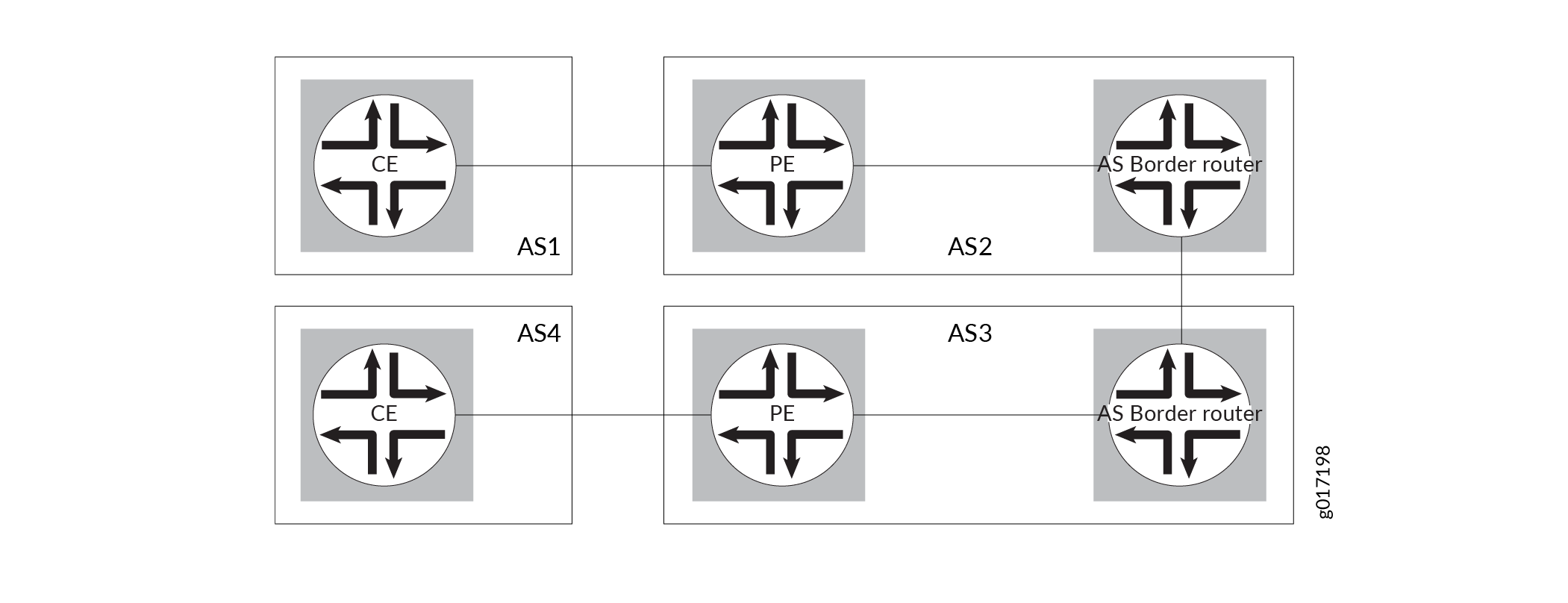
提供商间 VPN 在单独的 AS 之间提供连接。此功能可由与几个不同服务提供商建立连接或在不同地理区域(每个都使用不同的 AS)内与同一服务提供商建立不同连接的 VPN 客户使用。 图 1 说明了跨运营商VPN 使用的网络拓扑类型。
以下部分介绍了配置跨运营商VPN的方法:
在自治系统之间链接 VRF 表
只需将一个 AS 的 AS 边界路由器 (ASBR) 中的 VPN 路由和转发 (VRF) 表链接到另一个 AS 的 ASBR 中的 VRF 表,即可连接两个单独的 AS。每个 ASBR 必须为在两个服务提供商网络中配置的每个 VPN 都包含一个 VRF 路由实例。然后,在两个 ASBR 之间配置 IP 会话。实际上,ASBR 将彼此视为客户边缘 (CE) 路由器。
由于配置的复杂性,特别是在扩展方面,不建议使用此方法。文档中没有提供此配置的详细信息。
配置新一代 3 层 VPN 选项 A、B 和 C
对于新一代第 3 层 VPN,AS 中的 PE 路由器使用多协议外部 BGP (MP-EBGP) 将标记的 VPN – 互联网协议版本 4 (IPv4) 路由分发到 ASBR 或 ASBR 作为其客户端的路由反射器。ASBR 使用多协议外部 BGP (MP-EBGP) 将标记的 VPN-IPv4 路由分发给相邻 AS 中的对等 ASBR。然后,对等方 ASBR 使用 MP-IBGP 将标记的 VPN-IPv4 路由分发到 PE 路由器或 PE 路由器作为其客户端的路由反射器。
您可以跨 AS 配置单播(Junos OS 9.5 及更高版本)和组播(Junos OS 12.1 及更高版本)新一代第 3 层 VPN。Junos OS 软件支持新一代第 3 层 VPN 选项 A、选项 B 和选项 C:
选项 A — 这是一个简单但可扩展性较差的跨运营商VPN解决方案,用于向拥有不同站点(并非所有站点都可以使用同一服务提供商)的客户提供 VPN 服务的问题。在此实施中,一个 AS 的 ASBR 中的 VPN 路由和转发 (VRF) 表链接到另一个 AS 的 ASBR 中的 VRF 表。每个 ASBR 必须为在两个服务提供商网络中配置的每个 VPN 包含一个 VRF 实例。然后,必须在 ASBR 之间配置 IGP 或 BGP。
选项 B — 对于此跨运营商VPN 解决方案,客户需要为不同的站点提供 VPN 服务,但并非所有站点都使用相同的服务提供商。使用选项 B 时,ASBR 路由器将所有 VPN-IPv4 路由保留在路由信息库 (RIB) 中,而与前缀关联的标签则保留在转发信息库 (FIB) 中。由于 RIB 和 FIB 表可能会占用过多各自分配的内存,因此对于跨运营商VPN,此解决方案的可扩展性不高。如果在服务提供商 1 和服务提供商 2 之间使用传输服务提供商,则传输服务提供商还必须将所有 VPN-IPv4 路由保留在 RIB 中,并将相应的标签保留在 FIB 中。在此解决方案中,传输服务提供商的 ASBR 与服务提供商 1 或服务提供商 2 的 ASBR 具有相同的功能。每个 AS 内的 PE 路由器使用多协议内部 BGP (MP-IBGP) 将带标签的 VPN-IPv4 路由分发到 ASBR 或 ASBR 是其客户端的路由反射器。ASBR 使用 MP-EBGP 将标记的 VPN-IPv4 路由分发到相邻 AS 中的对等 ASBR 路由器。然后,对等方 ASBR 使用 MP-IBGP 将标记的 VPN-IPv4 路由分发到 PE 路由器或 PE 路由器作为其客户端的路由反射器。
选项 C — 对于此跨运营商VPN 解决方案,客户服务提供商依靠 VPN 服务提供商在客户服务提供商的接入点 (POP) 或区域网络之间提供 VPN 传输服务。此功能可由与多个不同服务提供商建立连接或在不同地理区域(每个都使用不同的 AS 编号)内与同一服务提供商建立不同连接的 VPN 客户使用。对于选项 C,仅在 ASBR 之间通告服务提供商网络内部的路由。这是通过使用
family inet labeled-unicastPE 路由器上的 IBGP 和 EBGP 配置中的语句来实现的。ASBR 交换标记的 IPv4(非 VPN-IPv4)路由以支持 MPLS。终端 PE 路由器之间的 MP-EBGP 会话用于宣布 VPN-IPv4 路由。以这种方式提供 VPN 连接,同时将 VPN-IPv4 路由排除在核心网络之外。
在 AS 边界路由器之间配置多跳 MP-EBGP
在这种类型的跨运营商VPN配置中,P 路由器不需要将所有路由存储在所有 VPN 中。只有 PE 路由器必须具有所有 VPN 路由。P 路由器只是将流量转发到 PE 路由器,不会存储或处理有关数据包目的地的任何信息。不同 AS 中的 AS 边界路由器之间的连接在 AS 之间转发流量,就像标签交换路径 (LSP) 的工作原理一样。
以下是以这种方式配置跨运营商VPN的基本步骤:
在源和目标 AS 之间配置带标记的 VPN-IPv4 路由的多跳 EBGP 重新分配。
配置 EBGP,将标记的 IPv4 路由从其 AS 重新分配到相邻的 AS。
在 VPN 的终端 PE 路由器上配置 MPLS。
另见
示例:配置提供商间第 3 层 VPN 选项 A
提供商间第 3 层 VPN 选项 A 可在 AS 边界路由器 (ASBR) 上提供提供商间 VRF 到 VRF 的连接。与选项 B 和选项 C 相比,选项 A 是可扩展性最低的解决方案。
此示例提供配置提供商间第 3 层 VPN 选项 A 的分步过程,当具有多个 AS 的客户需要该服务,并且并非所有客户的 AS 都可以由同一服务提供商提供服务时,这是推荐的 MPLS VPN 实施方法之一。它分为以下部分:
要求
此示例使用以下硬件和软件组件:
-
Junos OS 9.5 或更高版本。
-
8 台 M Series、T Series、TX 系列或 MX 系列瞻博网络路由器。
概述和拓扑
这是最简单、可扩展性最小的跨运营商VPN解决方案,可解决向拥有不同站点(并非所有站点都可以使用同一服务提供商 (SP))的客户提供 VPN 服务的问题。
RFC 4364 第 10 节将此方法称为 AS 边界路由器上的提供商间 VRF 到 VRF 连接。
在此配置中:
-
一个 AS 的 ASBR 中的虚拟路由和转发 (VRF) 表链接到另一个 AS 的 ASBR 中的 VRF 表。对于在两个服务提供商网络中配置的每个 VPN,每个 ASBR 都必须包含一个 VRF 实例。然后,必须在 ASBR 之间配置 IGP 或 BGP。这样做的缺点是限制了可伸缩性。
-
在此配置中,两个 SP 上的自治系统边界路由器 (ASBR) 都配置为常规 PE 路由器,并向相邻 SP 提供 MPLS L3 VPN 服务。
-
每台 PE 路由器都将其视为客户边缘 (CE) 路由器。ASBR 对于远程 SP 的 ASBR 充当常规 CE 路由器的角色。ASBR 将彼此视为 CE 设备。
-
一个自治系统 (AS) 中的提供商边缘 (PE) 路由器直接连接到另一个 AS 中的 PE 路由器。
-
两台 PE 路由器通过多个子接口连接,每个子接口至少对应一个子接口,其路由需要从 AS 传递到 AS 的 VPN。
-
PE 路由器将每个子接口与一个 VPN 路由和转发 (VRF) 表相关联,并使用 EBGP 将未标记的 IPv4 地址分发给彼此。
-
在此解决方案中,在两个 PE 上定义的所有公共 VPN 也必须在两个 SP 之间的一个或多个 ASBR 上定义。这不是一种可扩展性很强的方法,特别是当两个区域 SP 使用一个过渡 SP 进行互连时。
-
这是一个易于配置的过程,不需要在 AS 之间的边界上设置 MPLS。此外,它的扩展性不如其他推荐的过程。
网络拓扑如 图 2 所示。
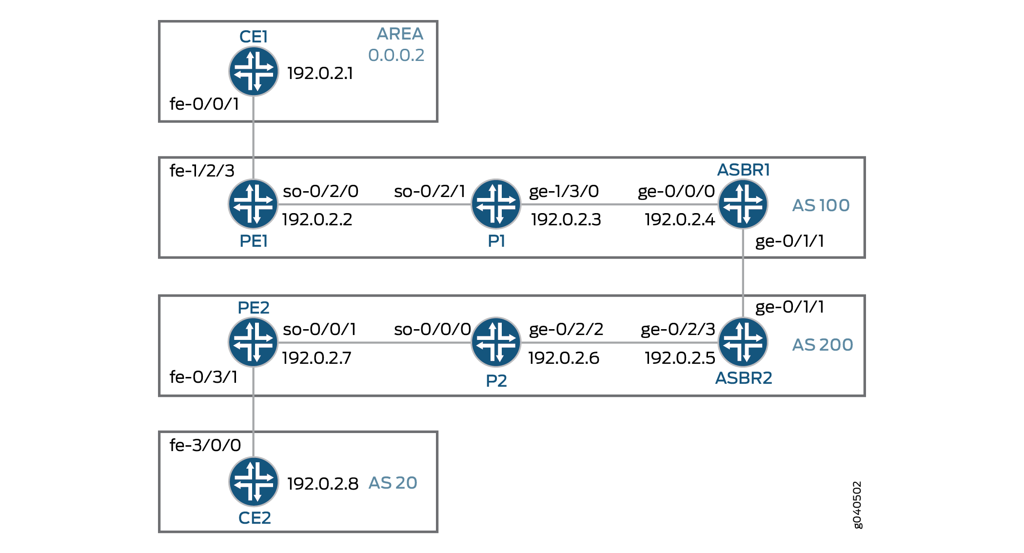
拓扑学
配置
此处介绍的过程是在假设读者已经熟悉 MPLS MVPN 配置的情况下编写的。此示例重点解释运营商的运营商解决方案对不同站点的 VPN 服务所需的独特配置。
要配置提供商间第 3 层 VPN 选项 A,请执行以下作:
配置路由器 CE1
分步过程
-
在路由器 CE1 上,为路由器 CE1 和路由器 PE1 之间的链路配置快速以太网接口上的 IP 地址和协议族。指定
inet地址族类型。[edit interfaces fe-0/0/1.0] family inet { address 198.51.100.1/24; } -
在路由器 CE1 上,配置环路接口上的 IP 地址和协议家族。指定
inet地址族类型。[edit interfaces lo0] unit 0 { family inet { address 192.0.2.1/32; } } -
在路由器 CE1 上,配置路由协议。路由协议可以是静态路由、RIP、OSPF、ISIS 或 EBGP。在此示例中,我们配置 OSPF。包括用于路由器 CE1 和路由器 PE1 之间链路的快速以太网接口以及路由器 CE1 的逻辑环路接口。
[edit protocols]
ospf {
    area 0.0.0.2 {
        interface fe-0/0/1.0;
        interface lo0.0;
    }
}
配置路由器 PE1
分步过程
-
在路由器 PE1 上,在 SONET、快速以太网和逻辑环路接口上配置 IPv4 地址。指定
inet所有接口上的地址族。指定mplsSONET 和快速以太网接口上的地址族。[edit interfaces] so-0/2/0 { unit 0 { family inet { address 192.168.1.9/24; } family mpls; } } fe-1/2/3 { unit 0 { family inet { address 198.51.100.2/24; } family mpls; } } lo0 { unit 0 { family inet { address 192.0.2.2/32; } } } -
在路由器 PE1 上,为 VPN2 配置路由实例。指定
vrf实例类型,并指定面向客户的快速以太网接口。配置路由识别符以创建唯一的 VPN-IPv4 地址前缀。应用 VRF 导入和导出策略以启用路由目标的发送和接收。在 VRF 中配置 OSPF 协议。指定面向客户的快速以太网接口,并指定导出策略以将 BGP 路由导出到 OSPF 中。[edit routing-instances] vpn2CE1 { instance-type vrf; interface fe-1/2/3.0; route-distinguisher 1:100; vrf-import vpnimport; vrf-export vpnexport; protocols { ospf { export bgp-to-ospf; area 0.0.0.2 { interface fe-1/2/3.0; } } } } -
在路由器 PE1 上,配置 RSVP 和 MPLS 协议以支持标签交换路径 (LSP)。将 LSP 配置为路由器 ASBR1,并指定路由器 ASBR1 上逻辑环路接口的 IP 地址。配置 BGP 组。将组类型指定为
internal。将本地地址指定为路由器 PE1 上的逻辑环路接口。将邻接方地址指定为路由器 ASBR1 上的逻辑环路接口。指定inet-vpn地址族和unicast流量类型,使 BGP 能够为 VPN 路由传输 IPv4 网络层可达性信息 (NLRI)。配置 OSPF 协议。指定面向核心的 SONET 接口,并指定路由器 PE1 上的逻辑环路接口。[edit protocols] rsvp { interface so-0/2/0.0; interface lo0.0; } mpls { label-switched-path To-ASBR1 { to 192.0.2.4; } interface so-0/2/0.0; interface lo0.0; } bgp { group To_ASBR1 { type internal; local-address 192.0.2.2; neighbor 192.0.2.4 { family inet-vpn { unicast; } } } } ospf { traffic-engineering; area 0.0.0.0 { interface so-0/2/0.0; interface lo0.0; } } -
在路由器 PE1 上,配置 BGP 本地自治系统编号。
[edit routing-options]
autonomous-system 100;
-
在路由器 PE1 上,配置将 BGP 路由导出到 OSPF 的策略。
[edit policy-options] policy-statement bgp-to-ospf { term 1 { from protocol bgp; then accept; } term 2 { then reject; } } -
在路由器 PE1 上,配置策略以将 VRF 路由目标添加到为此 VPN 播发的路由。
[edit policy-options] policy-statement vpnexport { term 1 { from protocol ospf; then { community add test_comm; accept; } } term 2 { then reject; } } -
在路由器 PE1 上,配置策略以从 BGP 导入附加了
test_comm社区的路由。[edit policy-options] policy-statement vpnimport { term 1 { from { protocol bgp; community test_comm; } then accept; } term 2 { then reject; } } -
在路由器 PE1 上,使用路由目标定义
test_commBGP 社区。[edit policy-options] community test_comm members target:1:100;
配置路由器 P1
分步过程
-
在路由器 P1 上,配置 SONET 和千兆以太网接口的 IP 地址。启用接口以处理
inet和mpls地址族。配置环路接口的lo0.0IP 地址,并使接口能够处理inet地址族。[edit interfaces] so-0/2/1 { unit 0 { family inet { address 192.168.1.4/24; } family mpls; } } ge-1/3/0 { unit 0 { family inet { address 192.168.2.5/24; } family mpls; } } lo0 { unit 0 { family inet { address 192.0.2.3/32; } } } -
在路由器 P1 上,配置 RSVP 和 MPLS 协议以支持 LSP。指定 SONET 和千兆以太网接口。
配置 OSPF 协议。指定 SONET 和千兆以太网接口,并指定逻辑环路接口。启用 OSPF 以支持流量工程扩展。
[edit protocols]
rsvp {
    interface so-0/2/1.0;
    interface ge-1/3/0.0;
    interface lo0.0;
}
mpls {
    interface lo0.0;
    interface ge-1/3/0.0;
    interface so-0/2/1.0;
}
ospf {
    traffic-engineering;
    area 0.0.0.0 {
        interface ge-1/3/0.0;
        interface so-0/2/1.0;
        interface lo0.0;
    }
}
配置路由器 ASBR1
分步过程
-
在路由器 ASBR1 上,配置千兆以太网接口的 IP 地址。启用接口以处理
inet和mpls地址系列。配置lo0.0环路接口的 IP 地址,并使接口能够处理inet地址族。[edit interfaces] ge-0/0/0 { unit 0 { family inet { address 192.168.2.6/24; } family mpls; } } ge-0/1/1 { unit 0 { family inet { address 192.168.3.7/24; } family mpls; } } lo0 { unit 0 { family inet { address 192.0.2.4/32; } } } -
在路由器 ASBR1 上,配置
To_ASBR2路由实例。指定vrf实例类型并指定面向核心的千兆以太网接口。配置路由识别符以创建唯一的 VPN-IPv4 地址前缀。为 VPN 配置路由目标。在 VRF 中配置 BGP 对等体组。将 AS 200 指定为对等 AS,并将路由器 ASBR2 上千兆以太网接口的 IP 地址指定为邻接方地址。[edit routing instances] To_ASBR2{ instance-type vrf; interface ge-0/1/1.0; route-distinguisher 1:100; vrf-target target:1:100; protocols { bgp { group To_ASBR2 { type external; neighbor 192.168.3.8 { peer-as 200; } } } } } -
在路由器 ASBR1 上,通过指定面向 P1 路由器的千兆以太网接口,将 RSVP 和 MPLS 协议配置为支持 LSP。
通过指定面向 P1 路由器的千兆以太网接口和逻辑环路接口来配置 OSPF 协议。启用 OSPF 以支持流量工程扩展。
[edit protocols] rsvp { interface ge-0/0/0.0; interface lo0.0; } mpls { label-switched-path To_PE1 { to 192.0.2.2; } interface lo0.0; interface ge-0/0/0.0; } ospf { traffic-engineering; area 0.0.0.0 { interface ge-0/0/0.0; interface lo0.0; } } -
在路由器 ASBR1 上,创建
To-PE1内部 BGP 对等体组。将本地 IP 对等方地址指定为本地lo0.0地址。将邻接方 IP 对等方地址指定为lo0.0路由器 PE1 的接口地址。[edit protocols] bgp { group To-PE1 { type internal; local-address 192.0.2.4; neighbor 192.0.2.2 { family inet-vpn { unicast; } } } } -
在路由器 ASBR1 上,配置 BGP 本地自治系统编号。
[edit routing-options]
autonomous-system 100;
配置路由器 ASBR2
分步过程
-
在路由器 ASBR2 上,配置千兆以太网接口的 IP 地址。启用接口以处理
inet和mpls地址族。配置环路接口的lo0.0IP 地址,并使接口能够处理inet地址族。[edit interfaces] ge-0/1/1 { unit 0 { family inet { address 192.168.3.8/24; } family mpls; } } ge-0/2/3 { unit 0 { family inet { address 192.168.4.10/24; } family mpls; } } lo0 { unit 0 { family inet { address 192.0.2.5/32; } } } -
在路由器 ASBR2 上,配置
To_ASBR1路由实例。指定vrf实例类型并指定面向核心的千兆以太网接口。配置路由识别符以创建唯一的 VPN-IPv4 地址前缀。为 VPN 配置路由目标。在 VRF 中配置 BGP 对等体组。将 AS 100 指定为对等 AS,并将路由器 ASBR1 上千兆以太网接口的 IP 地址指定为邻接方地址。[edit routing-instances] To_ASBR1 { instance-type vrf; interface ge-0/1/1.0; route-distinguisher 1:100; vrf-target target:1:100; protocols { bgp { group To_ASBR1 { type external; neighbor 192.168.3.7 { peer-as 100; } } } } } -
在路由器 ASBR2 上,通过指定面向 P2 路由器的千兆以太网接口,将 RSVP 和 MPLS 协议配置为支持 LSP。
通过指定面向 P2 路由器的千兆以太网接口和逻辑环路接口来配置 OSPF 协议。启用 OSPF 以支持流量工程扩展。
[edit protocols] rsvp { interface ge-0/2/3.0; interface lo0.0; } mpls { label-switched-path To_PE2 { to 192.0.2.7; } interface lo0.0; interface ge-0/2/3.0; } ospf { traffic-engineering; area 0.0.0.0 { interface ge-0/2/3.0; interface lo0.0; } } -
在路由器 ASBR2 上,创建
To-PE2内部 BGP 对等体组。将本地 IP 对等方地址指定为本地lo0.0地址。将邻接方 IP 对等方地址指定为lo0.0路由器 PE2 的接口地址。[edit protocols] bgp { group To-PE2 { type internal; local-address 192.0.2.5; neighbor 192.0.2.7 { family inet-vpn { unicast; } } } -
在路由器 ASBR2 上,配置 BGP 本地自治系统编号。
[edit routing-options]
autonomous-system 200;
配置路由器 P2
分步过程
-
在路由器 P2 上,配置 SONET 和千兆以太网接口的 IP 地址。启用接口以处理
inet和mpls地址族。配置环路接口的lo0.0IP 地址,并使接口能够处理inet地址族。[edit interfaces] so-0/0/0 { unit 0 { family inet { address 192.168.5.11/24; } family mpls; } } ge-0/2/2 { unit 0 { family inet { address 192.168.4.12/24; } family mpls; } } lo0 { unit 0 { family inet { address 192.0.2.6/32; } } } -
在路由器 P2 上,配置 RSVP 和 MPLS 协议以支持 LSP。指定 SONET 和千兆以太网接口。
配置 OSPF 协议。指定 SONET 和千兆以太网接口,并指定逻辑环路接口。启用 OSPF 以支持流量工程扩展。
[edit protocols]
rsvp {
    interface so-0/0/0.0;
    interface ge-0/2/2.0;
    interface lo0.0;
}
mpls {
    interface lo0.0;
    interface ge-0/2/2.0;
    interface so-0/0/0.0;
}
ospf {
    traffic-engineering;
    area 0.0.0.0 {
        interface ge-0/2/2.0;
        interface so-0/0/0.0;
        interface lo0.0;
    }
}
配置路由器 PE2
分步过程
-
在路由器 PE2 上,在 SONET、快速以太网和逻辑环路接口上配置 IPv4 地址。指定
inet所有接口上的地址族。指定mplsSONET 和快速以太网接口上的地址族。[edit interfaces] so-0/0/1 { unit 0 { family inet { address 192.168.5.12/24; } family mpls; } } fe-0/3/1 { unit 0 { family inet { address 192.168.6.13/24; } family mpls; } lo0 { unit 0 { family inet { address 192.0.2.7/32; } } } -
在路由器 PE2 上,为 VPN2 配置路由实例。指定
vrf实例类型,并指定面向客户的快速以太网接口。配置路由识别符以创建唯一的 VPN-IPv4 地址前缀。应用 VRF 导入和导出策略以启用路由目标的发送和接收。在 VRF 中配置 BGP 对等体组。将 AS20指定为对等 AS,并将路由器 CE2 上快速以太网接口的 IP 地址指定为邻接方地址。[edit routing-instances] vpn2CE2 { instance-type vrf; interface fe-0/3/1.0; route-distinguisher 1:100; vrf-import vpnimport; vrf-export vpnexport; protocols { bgp { group To_CE2 { peer-as 20; neighbor 192.168.6.14; } } } } -
在路由器 PE2 上,配置 RSVP 和 MPLS 协议以支持 LSP。将 LSP 配置为 ASBR2,并指定路由器 ASBR2 上逻辑环路接口的 IP 地址。配置 BGP 组。将组类型指定为
internal。将本地地址指定为路由器 PE2 上的逻辑环路接口。将邻接方地址指定为路由器 ASBR2 上的逻辑环路接口。指定inet-vpn地址族和unicast流量类型,以使 BGP 能够为 VPN 路由携带 IPv4 NLRI。配置 OSPF 协议。指定面向核心的 SONET 接口,并指定路由器 PE2 上的逻辑环路接口。[edit protocols] rsvp { interface so-0/0/1.0; interface lo0.0; } mpls { label-switched-path To-ASBR2 { to 192.0.2.5; } interface so-0/0/1.0; interface lo0.0; } bgp { group To_ASBR2 { type internal; local-address 192.0.2.7; neighbor 192.0.2.5 { family inet-vpn { unicast; } } } } ospf { traffic-engineering; area 0.0.0.0 { interface so-0/0/1.0; interface lo0.0; } } -
在路由器 PE2 上,配置 BGP 本地自治系统编号。
[edit routing-options]
autonomous-system 200;
-
在路由器 PE2 上,配置策略以将 VRF 路由目标添加到为此 VPN 播发的路由。
[edit policy-options] policy-statement vpnexport { term 1 { from protocol bgp; then { community add test_comm; accept; } } term 2 { then reject; } } -
在路由器 PE2 上,配置策略以从 BGP 导入附加了
test_comm社区的路由。[edit policy-options] policy-statement vpnimport { term 1 { from { protocol bgp; community test_comm; } then accept; } term 2 { then reject; } } -
在路由器 PE2 上,使用路由目标定义
test_commBGP 社区。[edit policy-options] community test_comm members target:1:100;
配置路由器 CE2
分步过程
-
在路由器 CE2 上,为路由器 CE2 和路由器 PE2 之间的链路在快速以太网接口上配置 IP 地址和协议家族。指定
inet地址族类型。[edit interfaces] fe-3/0/0 { unit 0 { family inet { address 192.168.6.14/24; } } } -
在路由器 CE2 上,在环路接口上配置 IP 地址和协议家族。指定
inet地址族类型。[edit interfaces lo0] lo0 { unit 0 { family inet { address 192.0.2.8/32; } } } -
在路由器 CE2 上,定义名为
myroutes接受直接路由的策略。[edit policy-options] policy-statement myroutes { from protocol direct; then accept; } -
在路由器 CE2 上,配置路由协议。路由协议可以是静态路由、RIP、OSPF、ISIS 或 EBGP。在本示例中,我们配置 EBGP。将 AS
200指定为对等 AS,并将 BGP 邻接方 IP 地址指定为路由器 PE2 的快速以太网接口。[edit protocols] bgp { group To_PE2 { neighbor 192.168.6.13 { export myroutes; peer-as 200; } } } -
在路由器 CE2 上,配置 BGP 本地自治系统编号。
[edit routing-options]
autonomous-system 20;
验证 VPN作
分步过程
-
在每台路由器上提交配置。
注意:此示例中显示的 MPLS 标签将与配置中使用的标签不同。
-
在路由器 PE1 上,使用
show ospf route命令显示路由实例的路由vpn2CE1。验证是否已从 OSPF 获192.0.2.1知路由。user@PE1> show ospf route instance vpn2CE1 Topology default Route Table: Prefix Path Route NH Metric NextHop Nexthop Type Type Type Interface addr/label 192.0.2.1 Intra Router IP 1 fe-1/2/3.0 198.51.100.1 192.0.2.1/32 Intra Network IP 1 fe-1/2/3.0 198.51.100.1 198.51.100.0/24 Intra Network IP 1 fe-1/2/3.0 198.51.100.1 -
在路由器 PE1 上,使用
show route advertising-protocol命令验证路由器 PE1 是否使用带有 VPN MPLS 标签的 MP-BGP 将路由播发192.0.2.1至路由器 ASBR1。user@PE1> show route advertising-protocol bgp 192.0.2.4 extensive vpn2CE1.inet.0: 6 destinations, 6 routes (6 active, 0 holddown, 0 hidden) * 192.0.2.1/32 (1 entry, 1 announced) BGP group To_PE1 type Internal Route Distinguisher: 1:100 VPN Label: 299856 Nexthop: Self Flags: Nexthop Change MED: 1 Localpref: 100 AS path: [100] I Communities: target:1:100 rte-type:0.0.0.2:1:0 -
在路由器 ASBR1 上,使用
show route receive-protocol命令验证路由器是否接收并接受192.0.2.1路由,并将其放入To_ASBR2.inet.0路由表。user@ASBR1> show route receive-protocol bgp 192.0.2.2 extensive inet.0: 7 destinations, 7 routes (7 active, 0 holddown, 0 hidden) inet.3: 1 destinations, 1 routes (1 active, 0 holddown, 0 hidden) To_ASBR2.inet.0: 4 destinations, 4 routes (4 active, 0 holddown, 0 hidden) * 192.0.2.1/32 (1 entry, 1 announced) Route Distinguisher: 1:100 VPN Label: 299856 Nexthop: 192.0.2.2 MED: 1 Localpref: 100 AS path: I Communities: target:1:100 rte-type:0.0.0.2:1:0 MPLS.0: 4 destinations, 4 routes (4 active, 0 holddown, 0 hidden) BGP.13VPN.0: 1 destinations, 1 routes (1 active, 0 holddown, 0 hidden) * 1:100:192.0.2.1/32 (1 entry, 0 announced) Route Distinguisher: 1:100 VPN Label: 299856 Nexthop: 192.0.2.2 MED: 1 Localpref: 100 AS path: I Communities: target:1:100 rte-type:0.0.0.2:1:0 -
在路由器 ASBR1 上,使用
show route advertising-protocol命令验证路由器 ASBR1 是否将路由播192.0.2.1发至路由器 ASBR2。user@ASBR1> show route advertising-protocol bgp 192.168.3.8 extensive To_ASBR2.inet.0: 4 destinations, 4 routes (4 active, 0 holddown, 0 hidden) * 192.0.2.1/32 (1 entry, 1 announced) BGP group To_ASBR2.inet.0 type External Nexthop: Self AS path: [100] I Communities: target:1:100 rte-type:0.0.0.2:1:0 -
在路由器 ASBR2 上,使用
show route receive-protocol命令验证路由器是否接收并接受192.0.2.1路由,并将其放入To_ASBR1.inet.0路由表中。user@ASBR2> show route receive-protocol bgp 192.168.3.7 extensive inet.0: 7 destinations, 7 routes (7 active, 0 holddown, 0 hidden) inet.3: 1 destinations, 1 routes (1 active, 0 holddown, 0 hidden) To_ASBR1.inet.0: 4 destinations, 4 routes (4 active, 0 holddown, 0 hidden) * 192.0.2.1/32 (1 entry, 1 announced) Accepted Nexthop: 192.168.3.7 AS path: 100 I Communities: target:1:100 rte-type:0.0.0.2:1:0 MPLS.0: 4 destinations, 4 routes (4 active, 0 holddown, 0 hidden) BGP.l3VPN.0: 1 destinations, 1 routes (1 active, 0 holddown, 0 hidden) -
在路由器 ASBR2 上,使用
show route advertising-protocol命令验证路由器 ASBR2 是否将路由播192.0.2.1发至路由器 PE2。user@ASBR2> show route advertising-protocol bgp 192.0.2.7 extensive To_ASBR1.inet.0: 4 destinations, 4 routes (4 active, 0 holddown, 0 hidden) * 192.0.2.1/32 (1 entry, 1 announced) BGP group To-PE2 type Internal Route Distinguisher: 1:100 VPN Label: 299936 Nexthop: Self Flags: Nexthop Change Localpref: 100 AS path: [200] 100 I Communities: target:1:100 rte-type:0.0.0.2:1:0 -
在路由器 PE2 上,使用
show route receive-protocol命令验证路由器是否接收并接受192.0.2.1路由,并将其放入vpn2CE2.inet.0路由表中。user@PE2> show route receive-protocol bgp 192.0.2.5 extensive inet.0: 12 destinations, 13 routes (12 active, 0 holddown, 0 hidden) inet.3: 1 destinations, 1 routes (1 active, 0 holddown, 0 hidden) __juniper_private1__.inet.0: 14 destinations, 14 routes (8 active, 0 holddown, 6 hidden) __juniper_private2__.inet.0: 1 destinations, 1 routes (0 active, 0 holddown, 1 hidden) vpn2CE2.inet.0: 5 destinations, 6 routes (5 active, 0 holddown, 0 hidden) * 192.0.2.1/32 (1 entry, 1 announced) Accepted Route Distinguisher: 1:100 VPN Label: 299936 Nexthop: 192.0.2.5 Localpref: 100 AS path: 100 I AS path: Recorded Communities: target:1:100 rte-type:0.0.0.2:1:0 -
在路由器 PE2 上,使用
show route advertising-protocol命令验证路由器 PE2 是否通过To_CE2对等组将路由播192.0.2.1发至路由器 CE2。user@PE2> show route advertising-protocol bgp 192.168.6.14 extensive vpn2CE2.0: 5 destinations, 6 routes (5 active, 0 holddown, 0 hidden) * 192.0.2.1/32 (1 entry, 1 announced) BGP group To_CE2 type External Nexthop: Self AS path: [200] 100 I Communities: target:1:100 rte-type:0.0.0.2:1:0 -
在路由器 CE2 上,使用
show route命令验证路由器 CE2 是否从路由器 PE2 接收192.0.2.1路由。user@CE2> show route 192.0.2.1 inet.0: 6 destinations, 6 routes (6 active, 0 holddown, 0 hidden) + = Active Route, - = Last Active, * = Both 192.0.2.1/32 *[BGP/170] 00:25:36, localpref 100 AS path: 200 100 I > to 192.168.6.13 via fe-3/0/0.0 -
在路由器 CE2 上,使用
ping命令并指定192.0.2.8为 ping 数据包的来源,以验证与路由器 CE1 的连接。user@CE2> ping 192.0.2.1 source 192.0.2.8 PING 192.0.2.1 (192.0.2.1): 56 data bytes 64 bytes from 192.0.2.1: icmp_seq=0 ttl=58 time=4.672 ms 64 bytes from 192.0.2.1: icmp_seq=1 ttl=58 time=10.480 ms 64 bytes from 192.0.2.1: icmp_seq=2 ttl=58 time=10.560 ms
-
在路由器 PE2 上,使用
show route命令验证发送的流量内部标签是否299936为 ,顶部标签为299776。user@PE2> show route 192.0.2.1 detail vpn2CE2.inet.0: 5 destinations, 6 routes (5 active, 0 holddown, 0 hidden) 192.0.2.1/32 (1 entry, 1 announced) *BGP Preference: 170/-101 Route Distinguisher: 1:100 Next hop type: Indirect Next-hop reference count: 6 Source: 192.0.2.5 Next hop type: Router, Next hop index: 648 Next hop: via so-0/0/1.0 weight 0x1, selected Label-switched-path To-ASBR2 Label operation: Push 299936, Push 299776(top) Protocol next hop: 192.0.2.5 Push 299984 Indirect next hop: 8c6109c 262143 State: <Secondary Active Int Ext> Local AS: 200 Peer AS: 200 Age: 3:37 Metric2: 2 Task: BGP_200.192.0.2.5+179 Announcement bits (3): 0-RT 1-KRT 2-BGP RT Background AS path: 100 I AS path: Recorded Communities: target:1:100 rte-type:0.0.0.2:1:0 Accepted VPN Label: 299984 Localpref: 100 Router ID: 192.0.2.5 Primary Routing Table BGP.l3VPN.0 -
在路由器 ASBR2 上,使用
show route table命令验证路由器 ASBR2 是否接收到流量。user@ASBR2# show route table mpls.0 detail 299936 (1 entry, 1 announced) *VPN Preference: 170 Next hop type: Router, Next hop index: 649 Next-hop reference count: 2 Source: 192.168.3.7 Next hop: 192.168.3.7 via ge-0/1/1.0, selected Label operation: Pop State: <Active Int Ext> Local AS: 200 Age: 9:54 Task: BGP RT Background Announcement bits (1): 0-KRT AS path: 100 I Ref Cnt: 1 Communities: target:1:100 rte-type:0.0.0.2:1:0 -
在路由器 ASBR2 上,使用
show route table命令验证路由器 ASBR2 是否接收到流量。user@ASBR2# show route 192.0.2.1 detail To_ASBR1.inet.0: 4 destinations, 4 routes (4 active, 0 holddown, 0 hidden) 192.0.2.1/32 (1 entry, 1 announced) *BGP Preference: 170/-101 Next hop type: Router, Next hop index: 576 Next-hop reference count: 3 Source: 192.168.3.7 Next hop: 192.168.3.7 via ge-0/1/1.0, selected State: <Active Ext> Peer AS: 100 Age: 13:07 Task: BGP_192.168.3.7+53372 Announcement bits (2): 0-KRT 1-BGP RT Background AS path: 100 I Communities: target:1:100 rte-type:0.0.0.2:1:0 Accepted Localpref: 100 Router ID: 192.168.3.7 -
在路由器 ASBR1 上,使用
show route命令验证 ASBR1 是否通过顶部标签299792和 VPN 标签299856向 PE1 发送流量。user@ASBR1# show route 192.0.2.1 detail To_ASBR2.inet.0: 4 destinations, 4 routes (4 active, 0 holddown, 0 hidden) 192.0.2.1/24 (1 entry, 1 announced) *BGP Preference: 170/-101 Route Distinguisher: 1:100 Next hop type: Indirect Next-hop reference count: 3 Source: 192.0.2.2 Next hop type: Router, Next hop index: 669 Next hop: 192.168.2.5 via ge-0/0/0.0 weight 0x1, selected Label-switched-path To_PE1 Label operation: Push 299856, Push 299792(top) Protocol next hop: 192.0.2.2 Push 299856 Indirect next hop: 8af70a0 262143 State: <Secondary Active Int Ext> Local AS: 100 Peer AS: 100 Age: 12:15 Metric: 1 Metric2: 2 Task: BGP_100.192.0.2.2+58065 Announcement bits (2): 0-KRT 1-BGP RT Background AS path: I Communities: target:1:100 rte-type:0.0.0.2:1:0 VPN Label: 299856 Localpref: 100 Router ID: 192.0.2.2 Primary Routing Table BGP.l3VPN.0 -
在路由器 PE1 上,使用
show route table命令验证路由器 PE1 是否接收到带有标签299856的流量,弹出标签,l 并将流量通过接口fe-1/2/3.0发送到路由器 CE1。lab@PE1# show route table mpls.0 detail 299856 (1 entry, 1 announced) *VPN Preference: 170 Next hop type: Router, Next hop index: 666 Next-hop reference count: 2 Next hop: 198.51.100.8 via fe-1/2/3.0, selected Label operation: Pop State: <Active Int Ext> Local AS: 100 Age: 17:38 Task: BGP RT Background Announcement bits (1): 0-KRT AS path: I Ref Cnt: 1 Communities: rte-type:0.0.0.2:1:0 -
在路由器 PE1 上,在路由器 P 弹出顶部标签并将流量通过接口
fe-1/2/3.0发送到路由器 CE1 之后,使用show route命令验证 PE1 是否接收到流量。lab@PE1# show route 192.0.2.1 detail vpn2CE1.inet.0: 6 destinations, 6 routes (6 active, 0 holddown, 0 hidden) 192.0.2.1/32 (1 entry, 1 announced) *OSPF Preference: 10 Next hop type: Router, Next hop index: 634 Next-hop reference count: 3 Next hop: 198.51.100.8 via fe-1/2/3.0, selected State: <Active Int> Age: 18:42 Metric: 1 Area: 0.0.0.2 Task: VPN2alice-OSPFv2 Announcement bits (2): 2-KRT 3-BGP RT Background AS path: I Communities: rte-type:0.0.0.2:1:0
示例:配置提供商间第 3 层 VPN 选项 B
提供商间第 3 层 VPN 选项 B 提供将标记的 VPN-IPv4 路由从 AS 到相邻 AS 的提供商间 EBGP 重新分配。该解决方案被认为比选项 A 更具可扩展性,但不如选项 C 具有可扩展性。
此示例提供配置提供商间第 3 层 VPN 选项 B 的分步过程,对于具有多个 AS(但并非所有客户的 AS 均可由同一服务提供商提供服务)的客户,这是 MPLS VPN 的推荐实施之一。它分为以下部分:
要求
此示例使用以下硬件和软件组件:
-
Junos OS 9.5 或更高版本。
- 此示例最近在 Junos OS 21.1R1 版上进行了更新和重新验证。
-
8 个 M Series、T Series、TX 系列、QFX10000 或 MX 系列 瞻博网络 路由器。
配置概述和拓扑
提供商间第 3 层 VPN 选项 B 是一种可扩展的解决方案,可解决向拥有不同站点的客户提供 VPN 服务的问题,并非所有站点都可以使用相同的服务提供商。 RFC 4364 第 10 节将此方法称为将标记的 VPN-IPv4 路由从 AS 到相邻 AS 的提供商间 EBGP 重新分配。
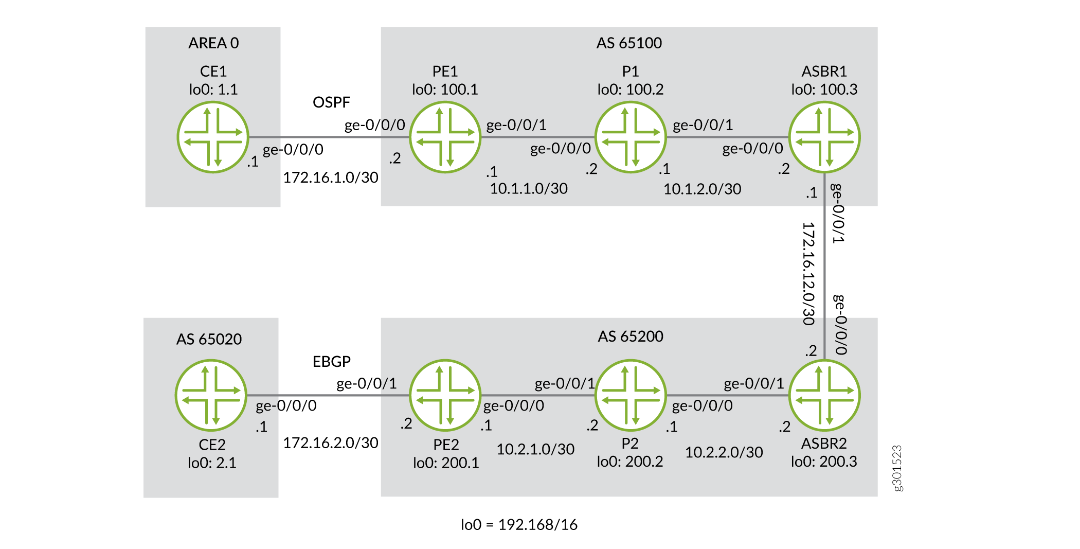
在图 1 所示的拓扑中,会发生以下事件:
-
PE 路由器使用 IBGP 将标记的 VPN-IPv4 路由重新分发到 ASBR。
-
然后,ASBR 使用 EBGP 将这些标记的 VPN-IPv4 路由重新分发到另一个 AS 中的 ASBR,后者再将其分发到该 AS 中的 PE 路由器。
-
标记的 VPN-IPv4 路由分布在每个站点的 ASBR 路由器之间。无需为驻留在两个不同 SP 上的每个公共 VPN 定义单独的 VPN 路由和转发实例 (VRF)。
-
路由器 PE2 使用 MP-IBGP 将 VPN-IPv4 路由分发到路由器 ASBR2。
-
路由器 ASBR2 使用路由器 ASBR1 之间的 MP-EBGP 会话,将这些带标记的 VPN-IPv4 路由分发给路由器 ASBR1。
-
路由器 ASBR1 使用 MP-IBGP 将这些路由重新分配给路由器 PE1。每次公布标签时,路由器都会更改下一跳信息和标签。
-
在路由器 PE1 和路由器 PE2 之间建立 MPLS 路径。此路径允许更改从邻居 SP 路由器获知的路由的下一跃点属性,并将给定路由的传入标签映射到向内部网络中的 PE 路由器播发的传出标签。
-
入口 PE 路由器在来自最终客户的 IP 数据包上插入两个标签。内部标签用于从内部 ASBR 获知的 VPN-IPv4 路由,外部标签用于通过资源预留协议 (RSVP) 或标签分发协议 (LDP) 获取到内部 ASBR 的路由。
-
当数据包到达 ASBR 时,它会移除外部标签(当使用显式 null 信令时;否则,倒数第二个跳弹出 (PHP) 会弹出标签),并将内部标签与通过 MP-EBGP 标签和前缀通告从相邻 ASBR 获取的标签交换。
-
第二个 ASBR 交换 VPN-IPv4 标签并推送另一个标签以到达其自身 AS 中的 PE 路由器。
-
其余过程与常规 VPN 相同。
在此解决方案中,ASBR 路由器将所有 VPN-IPv4 路由保留在路由信息库 (RIB) 中,而与前缀关联的标签则保留在转发信息库 (FIB) 中。由于 RIB 和 FIB 表可能会占用各自分配的大部分内存,因此此解决方案对于跨运营商VPN 的可扩展性不高。
如果在 SP1 和 SP2 之间使用过渡 SP,则过渡 SP 还必须将所有 VPN-IPv4 路由保留在 RIB 中,并将相应的标签保留在 FIB 中。在此解决方案中,过渡 SP 中的 ASBR 与 SP1 或 SP2 网络中的 ASBR 具有相同的功能。
配置
此处介绍的过程是在假设读者已经熟悉 MPLS MVPN 配置的情况下编写的。此示例重点解释运营商的运营商解决方案对不同站点的 VPN 服务所需的独特配置。
要配置第 3 层 VPN 选项 B,请执行以下作:
配置路由器 CE1
分步过程
-
在路由器 CE1 上,为路由器 CE1 和路由器 PE1 之间的链路在逻辑环路接口和千兆以太网接口上配置 IP 地址和协议族。指定
inet地址族类型。user@CE1# set interfaces ge-0/0/0 description to_PE1 set interfaces ge-0/0/0 unit 0 family inet address 172.16.1.1/30 set interfaces lo0 unit 0 family inet address 192.168.1.1/32
-
在路由器 CE1 上,配置路由器 ID。
user@CE1#
set routing-options router-id 192.168.1.1
-
在路由器 CE1 上,配置路由协议。包括路由器 CE1 和路由器 PE1 之间链路的逻辑接口以及路由器 CE1 的逻辑环路接口。路由协议可以是静态路由、RIP、OSPF、ISIS 或 EBGP。在此示例中,我们配置 OSPF。
user@CE1#
set protocols ospf area 0.0.0.0 interface ge-0/0/0.0
set protocols ospf area 0.0.0.0 interface lo0.0
配置路由器 PE1
分步过程
-
在路由器 PE1 上,在千兆以太网和逻辑环路接口上配置 IPv4 地址。指定
inet所有接口上的地址族。在面向核心的接口上指定mpls地址族。user@PE1# set interfaces ge-0/0/0 description to_CE1 set interfaces ge-0/0/0 unit 0 family inet address 172.16.1.2/30 set interfaces ge-0/0/1 description to_P1 set interfaces ge-0/0/1 unit 0 family inet address 10.1.1.1/30 set interfaces ge-0/0/1 unit 0 family mpls set interfaces lo0 unit 0 family inet address 192.168.100.1/32
-
在路由器 PE1 上,配置 VRF 路由实例。指定
vrf实例类型并指定面向客户的接口。配置路由识别符以创建唯一的 VPN-IPv4 地址前缀。应用 VRF 导入和导出策略以启用路由目标的发送和接收。在 VRF 中配置 OSPF 协议。指定面向客户的接口,并指定导出策略以将 BGP 路由导出到 OSPF 中。user@PE1# set routing-instances to_CE1 instance-type vrf set routing-instances to_CE1 protocols ospf area 0.0.0.0 interface ge-0/0/0.0 set routing-instances to_CE1 protocols ospf export bgp-to-ospf set routing-instances to_CE1 interface ge-0/0/0.0 set routing-instances to_CE1 route-distinguisher 192.168.100.1:1 set routing-instances to_CE1 vrf-import vpnimport set routing-instances to_CE1 vrf-export vpnexport
-
在路由器 PE1 上,配置 RSVP 和 MPLS 协议以支持标签交换路径 (LSP)。将 LSP 配置为路由器 ASBR1,并指定路由器 ASBR1 上逻辑环路接口的 IP 地址。配置 BGP 组。将组类型指定为
internal。将本地地址指定为路由器 PE1 上的逻辑环路接口。将邻接方地址指定为路由器 ASBR1 上的逻辑环路接口。指定inet-vpn地址族和unicast流量类型,使 BGP 能够为 VPN 路由传输 IPv4 网络层可达性信息 (NLRI)。配置 OSPF 协议。指定面向核心的接口,并指定路由器 PE1 上的逻辑环路接口。user@PE1# set protocols bgp group to-ASBR1 type internal set protocols bgp group to-ASBR1 local-address 192.168.100.1 set protocols bgp group to-ASBR1 neighbor 192.168.100.3 family inet-vpn unicast set protocols mpls label-switched-path to-ASBR1 to 192.168.100.3 set protocols mpls interface ge-0/0/1.0 set protocols mpls interface lo0.0 set protocols ospf traffic-engineering set protocols ospf area 0.0.0.0 interface ge-0/0/1.0 set protocols ospf area 0.0.0.0 interface lo0.0 set protocols rsvp interface ge-0/0/1.0 set protocols rsvp interface lo0.0
-
在路由器 PE1 上,配置 BGP 本地自治系统编号和路由器 ID。
user@PE1#
set routing-options router-id 192.168.100.1
set routing-options autonomous-system 65100
-
在路由器 PE1 上,配置将 BGP 路由导出到 OSPF 的策略。
user@PE1#
set policy-options policy-statement bgp-to-ospf term 1 from protocol bgp
set policy-options policy-statement bgp-to-ospf term 1 then accept
set policy-options policy-statement bgp-to-ospf term 2 then reject
-
在路由器 PE1 上,配置策略以将 VRF 路由目标添加到从 CE1 播发的路由。
user@PE1#
set policy-options policy-statement vpnexport term 1 from protocol ospf
set policy-options policy-statement vpnexport term 1 then community add pe1_comm
set policy-options policy-statement vpnexport term 1 then accept
set policy-options policy-statement vpnexport term 2 then reject
-
在路由器 PE1 上,配置策略以从 PE2 导入附加
pe2_comm了社区的路由。user@PE1# set policy-options policy-statement vpnimport term 1 from protocol bgp set policy-options policy-statement vpnimport term 1 from community pe2_comm set policy-options policy-statement vpnimport term 1 then accept set policy-options policy-statement vpnimport term 2 then reject
-
在路由器 PE1 上,使用要应用于vpnexport策略的路由目标定义
pe1_commBGP 社区,并使用要应用于vpnimport策略的pe2_comm路由目标定义 BGP 社区。user@PE1# set policy-options community pe1_comm members target:65100:1 set policy-options community pe2_comm members target:65200:1
配置路由器 P1
分步过程
-
在路由器 P1 上,配置千兆以太网接口的 IP 地址。启用接口以处理
inet和mpls地址族。配置lo0.0环路接口的 IP 地址,并使接口能够处理inet地址族。user@P1# set interfaces ge-0/0/0 description to_PE1 set interfaces ge-0/0/0 unit 0 family inet address 10.1.1.2/30 set interfaces ge-0/0/0 unit 0 family mpls set interfaces ge-0/0/1 description to_ASBR1 set interfaces ge-0/0/1 unit 0 family inet address 10.1.2.1/30 set interfaces ge-0/0/1 unit 0 family mpls set interfaces lo0 unit 0 family inet address 192.168.100.2/32
-
在路由器 P1 上,配置 RSVP 和 MPLS 协议以支持 LSP。指定千兆以太网接口。
配置 OSPF 协议。指定千兆以太网接口,并指定逻辑环路接口。启用 OSPF 以支持流量工程扩展。
user@P1#
set protocols mpls interface ge-0/0/0.0
set protocols mpls interface ge-0/0/1.0
set protocols mpls interface lo0.0
set protocols ospf traffic-engineering
set protocols ospf area 0.0.0.0 interface ge-0/0/0.0
set protocols ospf area 0.0.0.0 interface ge-0/0/1.0
set protocols ospf area 0.0.0.0 interface lo0.0
set protocols rsvp interface ge-0/0/0.0
set protocols rsvp interface ge-0/0/1.0
set protocols rsvp interface lo0.0
配置路由器 ASBR1
分步过程
-
在路由器 ASBR1 上,配置千兆以太网接口的 IP 地址。启用接口以处理
inet和mpls地址系列。配置lo0.0环路接口的 IP 地址,并使接口能够处理inet地址族。user@ASBR1# set interfaces ge-0/0/0 description to_P1 set interfaces ge-0/0/0 unit 0 family inet address 10.1.2.2/30 set interfaces ge-0/0/0 unit 0 family mpls set interfaces ge-0/0/1 description to_ASBR2 set interfaces ge-0/0/1 unit 0 family inet address 172.16.12.1/30 set interfaces ge-0/0/1 unit 0 family mpls set interfaces lo0 unit 0 family inet address 192.168.100.3/32
-
在路由器 ASBR1 上,通过指定面向 P1 路由器的千兆以太网接口和
lo0.0逻辑环路接口,将 RSVP 和 MPLS 协议配置为支持 LSP。通过指定面向 P1 路由器的千兆以太网接口和逻辑环路接口来配置 OSPF 协议。启用 OSPF 以支持流量工程扩展。
user@ASBR1#
set protocols mpls label-switched-path to-PE1 to 192.168.100.1
set protocols mpls interface ge-0/0/0.0
set protocols mpls interface lo0.0
set protocols ospf traffic-engineering
set protocols ospf area 0.0.0.0 interface ge-0/0/0.0
set protocols ospf area 0.0.0.0 interface lo0.0
set protocols rsvp interface ge-0/0/0.0
set protocols rsvp interface lo0.0
-
在路由器 ASBR1 上,创建
to-PE1内部 BGP 对等体组。将本地 IP 对等方地址指定为本地lo0.0地址。将邻接方 IP 对等方地址指定为lo0.0路由器 PE1 的接口地址。user@ASBR1# set protocols bgp group to-PE1 type internal set protocols bgp group to-PE1 local-address 192.168.100.3 set protocols bgp group to-PE1 neighbor 192.168.100.1 family inet-vpn unicast
-
在路由器 ASBR1 上,创建
to-ASBR2外部 BGP 对等体组。使路由器能够使用 BGP 通告单播路由的 NLRI。将邻接方 IP 对等方地址指定为路由器 ASBR2 的千兆以太网接口地址。user@ASBR1# set protocols bgp group to-ASBR2 type external set protocols bgp group to-ASBR2 family inet-vpn unicast set protocols bgp group to-ASBR2 neighbor 172.16.12.2 peer-as 65200
-
在路由器 ASBR1 上,配置 BGP 本地自治系统编号和路由器 ID。
user@ASBR1#
set routing-options router-id 192.168.100.3
set routing-options autonomous-system 65100
配置路由器 ASBR2
分步过程
-
在路由器 ASBR2 上,配置千兆以太网接口的 IP 地址。启用接口以处理
inet和mpls地址族。配置环路接口的lo0.0IP 地址,并使接口能够处理inet地址族。user@ASBR2# set interfaces ge-0/0/0 description to_ASBR1 set interfaces ge-0/0/0 unit 0 family inet address 172.16.12.2/30 set interfaces ge-0/0/0 unit 0 family mpls set interfaces ge-0/0/1 description to_P2 set interfaces ge-0/0/1 unit 0 family inet address 10.2.2.2/30 set interfaces ge-0/0/1 unit 0 family mpls set interfaces lo0 unit 0 family inet address 192.168.200.3/32
-
在路由器 ASBR2 上,通过指定面向 P2 路由器的千兆以太网接口,将 RSVP 和 MPLS 协议配置为支持 LSP。
通过指定面向 P2 路由器的千兆以太网接口和逻辑环路接口来配置 OSPF 协议。启用 OSPF 以支持流量工程扩展。
user@ASBR2#
set protocols mpls label-switched-path to-PE2 to 192.168.200.1
set protocols mpls interface ge-0/0/1.0
set protocols mpls interface lo0.0
set protocols ospf traffic-engineering
set protocols ospf area 0.0.0.0 interface ge-0/0/1.0
set protocols ospf area 0.0.0.0 interface lo0.0
set protocols rsvp interface ge-0/0/1.0
set protocols rsvp interface lo0.0
-
在路由器 ASBR2 上,创建
to-PE2内部 BGP 对等体组。将本地 IP 对等方地址指定为本地lo0.0地址。将邻接方 IP 对等方地址指定为lo0.0路由器 PE2 的接口地址。user@ASBR2# set protocols bgp group to-PE2 type internal set protocols bgp group to-PE2 local-address 192.168.200.3 set protocols bgp group to-PE2 neighbor 192.168.200.1 family inet-vpn unicast
-
在路由器 ASBR2 上,创建
to-ASBR1外部 BGP 对等体组。使路由器能够使用 BGP 通告单播路由的 NLRI。将邻接方 IP 对等方地址指定为路由器 ASBR1 上的千兆以太网接口。user@ASBR2# set protocols bgp group to-ASBR1 type external set protocols bgp group to-ASBR1 family inet-vpn unicast set protocols bgp group to-ASBR1 neighbor 172.16.12.1 peer-as 65100
-
在路由器 ASBR2 上,配置 BGP 本地自治系统编号和路由器 ID。
user@ASBR2#
set routing-options router-id 192.168.200.3
set routing-options autonomous-system 65200
配置路由器 P2
分步过程
-
在路由器 P2 上,配置千兆以太网接口的 IP 地址。启用接口以处理
inet和mpls地址族。配置环路接口的lo0.0IP 地址,并使接口能够处理inet地址族。user@P2# set interfaces ge-0/0/0 description to_ASBR2 set interfaces ge-0/0/0 unit 0 family inet address 10.2.2.1/30 set interfaces ge-0/0/0 unit 0 family mpls set interfaces ge-0/0/1 description to_PE2 set interfaces ge-0/0/1 unit 0 family inet address 10.2.1.2/30 set interfaces ge-0/0/1 unit 0 family mpls set interfaces lo0 unit 0 family inet address 192.168.200.2/32
-
在路由器 P2 上,配置 RSVP 和 MPLS 协议以支持 LSP。指定千兆以太网接口。
配置 OSPF 协议。指定千兆以太网接口,并指定逻辑环路接口。启用 OSPF 以支持流量工程扩展。
user@P2#
set protocols mpls interface ge-0/0/0.0
set protocols mpls interface ge-0/0/1.0
set protocols mpls interface lo0.0
set protocols ospf traffic-engineering
set protocols ospf area 0.0.0.0 interface ge-0/0/0.0
set protocols ospf area 0.0.0.0 interface ge-0/0/1.0
set protocols ospf area 0.0.0.0 interface lo0.0
set protocols rsvp interface ge-0/0/0.0
set protocols rsvp interface ge-0/0/1.0
set protocols rsvp interface lo0.0
配置路由器 PE2
分步过程
-
在路由器 PE2 上,在千兆以太网和逻辑环路接口上配置 IPv4 地址。指定
inet所有接口上的地址族。指定mpls千兆以太网接口上的地址族。user@PE2# set interfaces ge-0/0/0 description to_P2 set interfaces ge-0/0/0 unit 0 family inet address 10.2.1.1/30 set interfaces ge-0/0/0 unit 0 family mpls set interfaces ge-0/0/1 description to_CE2 set interfaces ge-0/0/1 unit 0 family inet address 172.16.2.2/30 set interfaces lo0 unit 0 family inet address 192.168.200.1/32
-
在路由器 PE2 上,配置 VRF 路由实例。指定
vrf实例类型并指定面向客户的接口。配置路由识别符以创建唯一的 VPN-IPv4 地址前缀。应用 VRF 导入和导出策略以启用路由目标的发送和接收。在 VRF 中配置 BGP 对等体组。将 AS65020指定为对等 AS,并将路由器 CE1 上千兆以太网接口的 IP 地址指定为邻接方地址。user@PE2# set routing-instances to_CE2 instance-type vrf set routing-instances to_CE2 protocols bgp group to_CE2 peer-as 65020 set routing-instances to_CE2 protocols bgp group to_CE2 neighbor 172.16.2.1 set routing-instances to_CE2 interface ge-0/0/1.0 set routing-instances to_CE2 route-distinguisher 192.168.200.1:1 set routing-instances to_CE2 vrf-import vpnimport set routing-instances to_CE2 vrf-export vpnexport
-
在路由器 PE2 上,配置 RSVP 和 MPLS 协议以支持 LSP。将 LSP 配置为 ASBR2,并指定路由器 ASBR2 上逻辑环路接口的 IP 地址。配置 BGP 组。将组类型指定为
internal。将本地地址指定为路由器 PE2 上的逻辑环路接口。将邻接方地址指定为路由器 ASBR2 上的逻辑环路接口。指定inet-vpn地址族和unicast流量类型,以使 BGP 能够为 VPN 路由携带 IPv4 NLRI。配置 OSPF 协议。在路由器 PE2 上指定面向核心的接口和逻辑环路接口。user@PE2# set protocols bgp group to-ASBR2 type internal set protocols bgp group to-ASBR2 local-address 192.168.200.1 set protocols bgp group to-ASBR2 neighbor 192.168.200.3 family inet-vpn unicast set protocols mpls label-switched-path to-ASBR2 to 192.168.200.3 set protocols mpls interface ge-0/0/0.0 set protocols mpls interface lo0.0 set protocols ospf traffic-engineering set protocols ospf area 0.0.0.0 interface ge-0/0/0.0 set protocols ospf area 0.0.0.0 interface lo0.0 set protocols rsvp interface ge-0/0/0.0 set protocols rsvp interface lo0.0
-
在路由器 PE2 上,配置 BGP 本地自治系统编号和路由器 ID。
user@PE2#
set routing-options router-id 192.168.200.1
set routing-options autonomous-system 65200
-
在路由器 PE2 上,配置策略以将 VRF 路由目标添加到从 CE2 播发的路由。
user@PE2#
set policy-options policy-statement vpnexport term 1 from protocol bgp
set policy-options policy-statement vpnexport term 1 then community add pe2_comm
set policy-options policy-statement vpnexport term 1 then accept
set policy-options policy-statement vpnexport term 2 then reject
-
在路由器 PE2 上,配置策略以从 PE1 导入附加
pe1_comm了社区的路由。user@PE2# set policy-options policy-statement vpnimport term 1 from protocol bgp set policy-options policy-statement vpnimport term 1 from community pe1_comm set policy-options policy-statement vpnimport term 1 then accept set policy-options policy-statement vpnimport term 2 then reject
-
在路由器 PE2 上,使用要应用于vpnexport策略的路由目标定义
pe2_commBGP 社区,并使用要应用于vpnimport策略的pe1_comm路由目标定义 BGP 社区user@PE2# set policy-options community pe1_comm members target:65100:1 set policy-options community pe2_comm members target:65200:1
配置路由器 CE2
分步过程
-
在路由器 CE2 上,为路由器 CE2 和路由器 PE2 之间的链路配置逻辑环路接口和千兆以太网接口上的 IP 地址和协议家族。指定
inet地址族类型。user@CE2# set interfaces ge-0/0/0 description to_PE2 set interfaces ge-0/0/0 unit 0 family inet address 172.16.2.1/30 set interfaces lo0 unit 0 family inet address 192.168.2.1/32
-
在路由器 CE2 上,定义一个名为
loopback的策略,该策略与 CE2 的环路地址匹配。user@CE2# set policy-options policy-statement loopback term 1 from route-filter 192.168.2.1/32 exact set policy-options policy-statement loopback term 1 then accept
-
在路由器 CE2 上,配置路由协议。路由协议可以是静态路由、RIP、OSPF、ISIS 或 EBGP。在本示例中,我们配置 EBGP。将 AS
65200指定为对等 AS,并将 BGP 邻接方 IP 地址指定为路由器 PE2 的千兆以太网接口。包括export语句。user@CE2# set protocols bgp group to_PE2 export loopback set protocols bgp group to_PE2 peer-as 65200 set protocols bgp group to_PE2 neighbor 172.16.2.2
-
在路由器 CE2 上,配置 BGP 本地自治系统编号和路由器 ID。
user@CE2#
set routing-options router-id 192.168.2.1
set routing-options autonomous-system 65020
验证 VPN作
分步过程
-
在每台路由器上提交配置。
注意:此示例中显示的 MPLS 标签将与配置中使用的标签不同。
-
在路由器 PE1 上,使用
show ospf route命令显示路由实例的路由to_CE1。验证是否已从 OSPF 获192.168.1.1知路由。user@PE1> show ospf route instance to_CE1 Topology default Route Table: Prefix Path Route NH Metric NextHop Nexthop Type Type Type Interface Address/LSP 192.168.1.1 Intra Router IP 1 ge-0/0/0.0 172.16.1.1 172.16.1.0/30 Intra Network IP 1 ge-0/0/0.0 192.168.1.1/32 Intra Network IP 1 ge-0/0/0.0 172.16.1.1 -
在路由器 PE1 上,使用
show route advertising-protocol命令验证路由器 PE1 是否使用带有 VPN MPLS 标签的 MP-BGP 将路由播发192.168.1.1至路由器 ASBR1。user@PE1> show route advertising-protocol bgp 192.168.100.3 extensive to_CE1.inet.0: 5 destinations, 5 routes (5 active, 0 holddown, 0 hidden) * 192.168.1.1/32 (1 entry, 1 announced) BGP group to-ASBR1 type Internal Route Distinguisher: 192.168.100.1:1 VPN Label: 299808 Nexthop: Self Flags: Nexthop Change MED: 1 Localpref: 100 AS path: [65100] I Communities: target:65100:1 rte-type:0.0.0.0:1:0 -
在路由器 ASBR1 上,使用
show route receive-protocol命令验证路由器是否接收并接受192.168.1.1路由,并将其放入bgp.l3vpn.0路由表。user@ASBR1> show route receive-protocol bgp 192.168.100.1 extensive inet.0: 15 destinations, 15 routes (15 active, 0 holddown, 0 hidden) inet.3: 1 destinations, 1 routes (1 active, 0 holddown, 0 hidden) mpls.0: 6 destinations, 6 routes (6 active, 0 holddown, 0 hidden) bgp.l3vpn.0: 2 destinations, 2 routes (2 active, 0 holddown, 0 hidden) * 192.168.100.1:1:192.168.1.1/32 (1 entry, 1 announced) Accepted Route Distinguisher: 192.168.100.1:1 VPN Label: 299808 Nexthop: 192.168.100.1 MED: 1 Localpref: 100 AS path: I Communities: target:65100:1 rte-type:0.0.0.0:1:0 -
在路由器 ASBR1 上,使用
show route advertising-protocol命令验证路由器 ASBR1 是否将路由播192.168.1.1发至路由器 ASBR2。user@ASBR1> show route advertising-protocol bgp 172.16.12.2 extensive bgp.l3vpn.0: 2 destinations, 2 routes (2 active, 0 holddown, 0 hidden) * 192.168.100.1:1:192.168.1.1/32 (1 entry, 1 announced) BGP group to-ASBR2 type External Route Distinguisher: 192.168.100.1:1 VPN Label: 299824 Nexthop: Self Flags: Nexthop Change AS path: [65100] I Communities: target:65100:1 rte-type:0.0.0.0:1:0 -
在路由器 ASBR2 上,使用
show route receive-protocol命令验证路由器是否接收并接受192.168.1.1路由,并将其放入bgp.l3vpn.0路由表中。user@ASBR2> show route receive-protocol bgp 172.16.12.1 extensive inet.0: 15 destinations, 15 routes (15 active, 0 holddown, 0 hidden) inet.3: 1 destinations, 1 routes (1 active, 0 holddown, 0 hidden) mpls.0: 6 destinations, 6 routes (6 active, 0 holddown, 0 hidden) bgp.l3vpn.0: 2 destinations, 2 routes (2 active, 0 holddown, 0 hidden) * 192.168.100.1:1:192.168.1.1/32 (1 entry, 1 announced) Accepted Route Distinguisher: 192.168.100.1:1 VPN Label: 299824 Nexthop: 172.16.12.1 AS path: 65100 I Communities: target:65100:1 rte-type:0.0.0.0:1:0 -
在路由器 ASBR2 上,使用
show route advertising-protocol命令验证路由器 ASBR2 是否将路由播192.168.1.1发至路由器 PE2。user@ASBR2> show route advertising-protocol bgp 192.168.200.1 extensive bgp.l3vpn.0: 2 destinations, 2 routes (2 active, 0 holddown, 0 hidden) * 192.168.100.1:1:192.168.1.1/32 (1 entry, 1 announced) BGP group to-PE2 type Internal Route Distinguisher: 192.168.100.1:1 VPN Label: 299824 Nexthop: Self Flags: Nexthop Change Localpref: 100 AS path: [65200] 65100 I Communities: target:65100:1 rte-type:0.0.0.0:1:0 -
在路由器 PE2 上,使用
show route receive-protocol命令验证路由器是否接收并接受192.168.1.1路由,并将其放入to_CE2.inet.0路由表中。user@PE2> show route receive-protocol bgp 192.168.200.3 extensive inet.0: 13 destinations, 13 routes (13 active, 0 holddown, 0 hidden) inet.3: 1 destinations, 1 routes (1 active, 0 holddown, 0 hidden) to_CE2.inet.0: 4 destinations, 4 routes (4 active, 0 holddown, 0 hidden) * 192.168.1.1/32 (1 entry, 1 announced) Import Accepted Route Distinguisher: 192.168.100.1:1 VPN Label: 299824 Nexthop: 192.168.200.3 Localpref: 100 AS path: 65100 I Communities: target:65100:1 rte-type:0.0.0.0:1:0 mpls.0: 5 destinations, 5 routes (5 active, 0 holddown, 0 hidden) bgp.l3vpn.0: 1 destinations, 1 routes (1 active, 0 holddown, 0 hidden) * 192.168.100.1:1:192.168.1.1/32 (1 entry, 0 announced) Import Accepted Route Distinguisher: 192.168.100.1:1 VPN Label: 299824 Nexthop: 192.168.200.3 Localpref: 100 AS path: 65100 I Communities: target:65100:1 rte-type:0.0.0.0:1:0 inet6.0: 1 destinations, 1 routes (1 active, 0 holddown, 0 hidden) to_CE2.inet6.0: 1 destinations, 1 routes (1 active, 0 holddown, 0 hidden) -
在路由器 PE2 上,使用
show route advertising-protocol命令验证路由器 PE2 是否通过to_CE2对等组将路由播192.168.1.1发至路由器 CE2。user@PE2> show route advertising-protocol bgp 172.16.2.1 extensive to_CE2.inet.0: 4 destinations, 4 routes (4 active, 0 holddown, 0 hidden) * 192.168.1.1/32 (1 entry, 1 announced) BGP group to_CE2 type External Nexthop: Self AS path: [65200] 65100 I Communities: target:65100:1 rte-type:0.0.0.0:1:0 -
在路由器 CE2 上,使用
show route命令验证路由器 CE2 是否从路由器 PE2 接收192.168.1.1路由。user@CE2> show route 192.168.1.1 inet.0: 10 destinations, 10 routes (10 active, 0 holddown, 0 hidden) + = Active Route, - = Last Active, * = Both 192.168.1.1/32 *[BGP/170] 6d 02:09:53, localpref 100 AS path: 65200 65100 I, validation-state: unverified > to 172.16.2.2 via ge-0/0/0.0 -
在路由器 CE2 上,使用
ping命令并指定192.168.2.1为 ping 数据包的来源,以验证与路由器 CE1 的连接。user@CE2> ping 192.168.1.1 source 192.168.2.1 count 2 PING 192.168.1.1 (192.168.1.1): 56 data bytes 64 bytes from 192.168.1.1: icmp_seq=0 ttl=58 time=27.008 ms 64 bytes from 192.168.1.1: icmp_seq=1 ttl=58 time=40.004 ms --- 192.168.1.1 ping statistics --- 2 packets transmitted, 2 packets received, 0% packet loss round-trip min/avg/max/stddev = 27.008/33.506/40.004/6.498 ms
注意:要在不从环路采购的情况下进行端到端 ping作,请确保通告 PE 到 CE 接口路由。您可以通过几种方式完成此作,但对于此示例,请将协议直接添加到
vpnexportPE1 和 PE2 上的策略中。
示例:配置提供商间第 3 层 VPN 选项 C
提供商间第 3 层 VPN 选项 C 提供在源和目标 AS 之间标记的 VPN-IPv4 路由的运营商间多跳 EBGP 重新分配,并将标记的 IPv4 路由从 AS 重新分配到相邻 AS。相较于选项 A 和选项 B,选项 C 是最具可扩展性的解决方案。要配置提供商间第 3 层 VPN 选项 C 服务,您需要使用多跳 EBGP 配置 AS 边界路由器和连接到最终客户 CE 路由器的 PE 路由器。
此示例提供配置提供商间第 3 层 VPN 的分步过程 选项 C,当拥有多个 AS 但并非所有客户的 AS 都可以由同一服务提供商 (SP) 提供服务时,这是建议的 MPLS VPN 实施方法之一。它分为以下部分:
要求
此示例需要以下硬件和软件组件:
-
Junos OS 9.5 或更高版本。
-
8 个瞻博网络 M Series 多服务边缘路由器、T Series 核心路由器、TX Matrix 路由器或 MX 系列 5G 通用路由平台。
配置概述和拓扑
跨运营商第 3 层 VPN 选项 C 是一种可扩展性很强的跨运营商VPN 解决方案,可解决向拥有不同站点(并非所有站点都可以使用相同 SP)的客户提供 VPN 服务的问题。
RFC 4364 第 10 节将此方法称为源和目标 AS 之间标记的 VPN-IPv4 路由的多跳 EBGP 重新分配,并将标记的 IPv4 路由从 AS 重新分配到相邻 AS。
此解决方案与 实施提供商间第 3 层 VPN 选项 B 中所述的解决方案类似,不同之处在于使用 EBGP 播发内部 IPv4 单播路由,而不是外部 VPN-IPv4 单播路由。内部路由是叶 SP(此例中为 SP1 和 SP2)的内部路由,外部路由是从请求 VPN 服务的最终客户那里获知的路由。
在此配置中:
-
路由器 PE1 学习路由器 PE2 的环路地址,路由器 PE2 学习路由器 PE1 的环路地址后,终端 PE 路由器将建立 MP-EBGP 会话,用于交换 VPN-IPv4 路由。
-
由于 VPN-IPv4 路由在终端 PE 路由器之间进行交换,因此从路由器 PE1 和路由器 PE2 开始,路径上的任何其他路由器都无需在其路由信息库 (RIB) 或转发信息库 (FIB) 表中保留或安装 VPN-IPv4 路由。
-
需要在路由器 PE1 和路由器 PE2 之间建立 MPLS 路径。
RFC 4364 仅描述了一种使用 BGP 标记单播方法的解决方案。在这种方法中,ASBR 路由器通告 PE 路由器的环路地址,并根据 RFC 3107 将每个前缀与标签相关联。服务提供商可以使用 RSVP 或 LDP 在其内部网络中的 ASBR 路由器和 PE 路由器之间建立 LSP。
在此网络中,ASBR1 接收与路由器 PE1 的环路 IP 地址关联的标签信息,并使用 MP-EBGP 标签单播将另一个标签播发至路由器 ASBR2。同时,ASBR 根据接收和播发的路由和标签构建自己的 MPLS 转发表。路由器 ASBR1 使用自己的 IP 地址作为下一跃点信息。
路由器 ASBR2 接收与标签关联的此前缀,分配另一个标签,将下一跃点地址更改为自己的地址,并将其播发至路由器 PE1。路由器 PE1 现在更新了标签信息,以及路由器 ASBR1 的下一跃点。此外,路由器 PE1 已具有与路由器 ASBR1 的 IP 地址相关联的标签。如果路由器 PE1 向路由器 PE2 发送 IP 数据包,则会推送两个标签:一个是路由器 PE2 的 IP 地址(使用 MP-IBGP 标记单播通告获取),另一个是路由器 ASBR1 的 IP 地址(使用 LDP 或 RSVP 获取)。
然后,路由器 ASBR1 会弹出外部标签,并将内部标签与从相邻 ASBR 获知的标签交换为其相邻 PE 路由器。路由器 ASBR2 执行类似的功能,并交换传入标签(仅一个)并推送另一个与路由器 PE2 地址关联的标签。路由器 PE2 弹出这两个标签,并将剩余的 IP 数据包传递到自己的 CPU。PE路由器之间创建端到端连接后,PE路由器将建立MP-EBGP会话,进行VPN-IPv4路由交换。
在此解决方案中,PE 路由器将三个标签推送到来自 VPN 最终用户的 IP 数据包上。使用 MP-EBGP 获取的最内层标签可确定远程 PE 上正确的 VPN 路由和转发 (VRF) 路由实例。中间标签与远程 PE 的 IP 地址相关联,并通过 MP-IBGP 标签单播从 ASBR 获取。外部标签与 ASBR 的 IP 地址相关联,可使用 LDP 或 RSVP 获取。
网络的物理拓扑如 图 4 所示。
拓扑学
配置
此处介绍的过程是在假设读者已经熟悉 MPLS MVPN 配置的情况下编写的。此示例重点解释运营商的运营商解决方案对不同站点的 VPN 服务所需的独特配置。
要配置提供商间第 3 层 VPN 选项 C,请执行以下作:
配置路由器 CE1
分步过程
-
在路由器 CE1 上,为路由器 CE1 和路由器 PE1 之间的链路配置快速以太网接口上的 IP 地址和协议族。指定
inet地址族类型。[edit interfaces fe-0/0/1.0] family inet { address 198.51.100.1/24; } -
在路由器 CE1 上,配置环路接口上的 IP 地址和协议家族。指定
inet地址族类型。[edit interfaces lo0] unit 0 { family inet { address 192.0.2.1/32; } } -
在路由器 CE1 上,配置路由协议。路由协议可以是静态路由、RIP、OSPF、ISIS 或 EBGP。在此示例中,我们配置 OSPF。包括路由器 CE1 和路由器 PE1 之间链路的逻辑接口以及路由器 CE1 的逻辑环路接口。
[edit protocols]
ospf {
    area 0.0.0.2 {
        interface fe-0/0/1.0;
        interface lo0.0 {
            passive;
        }
    }
}
配置路由器 PE1
分步过程
-
在路由器 PE1 上,在 SONET、快速以太网和逻辑环路接口上配置 IPv4 地址。指定
inet所有接口上的地址族。指定mplsSONET 接口上的地址族。[edit interfaces] so-0/2/0 { unit 0 { family inet { address 192.168.1.2/24; } family mpls; } } fe-1/2/3 { unit 0 { family inet { address 198.51.100.3/24; } } } lo0 { unit 0 { family inet { address 192.0.2.2/32; } } } -
在路由器 PE1 上,为 VPN2 配置路由实例。指定
vrf实例类型,并指定面向客户的快速以太网接口。配置路由识别符以创建唯一的 VPN-IPv4 地址前缀。应用 VRF 导入和导出策略以启用路由目标的发送和接收。在 VRF 中配置 OSPF 协议。指定面向客户的快速以太网接口,并指定导出策略以将 BGP 路由导出到 OSPF 中。[edit routing-instances] vpn2CE1 { instance-type vrf; interface fe-1/2/3.0; route-distinguisher 1:100; vrf-import vpnimport; vrf-export vpnexport; protocols { ospf { export bgp-to-ospf; area 0.0.0.2 { interface fe-1/2/3.0; } } } } -
在路由器 PE1 上,配置 RSVP 和 MPLS 协议以支持 LSP。将 LSP 配置为路由器 ASBR1,并指定路由器 ASBR1 上逻辑环路接口的 IP 地址。配置 OSPF 协议。指定面向核心的 SONET 接口,并指定路由器 PE1 上的逻辑环路接口。
[edit protocols] rsvp { interface so-0/2/0.0; interface lo0.0; } mpls { label-switched-path To-ASBR1 { to 192.0.2.4; } interface so-0/2/0.0; interface lo0.0; } ospf { traffic-engineering; area 0.0.0.0 { interface so-0/2/0.0; interface lo0.0 { passive; } } } -
在路由器 PE1 上,配置
To_ASBR1对等 BGP 组。将组类型指定为internal。将本地地址指定为路由器 PE1 上的逻辑环路接口。将邻接方地址指定为路由器 ASBR1 上的逻辑环路接口。指定inet地址族。要使 PE 路由器要在 VRF 中安装路由,下一跃点必须解析为表中存储的inet.3路由。这些labeled-unicast resolve-vpn语句允许将标记好的路由放置在路由表中inet.3以进行路由解析,然后针对远程 PE 位于其他 AS 的 PE 路由器连接进行解析。[edit protocols] bgp { group To_ASBR1 { type internal; local-address 192.0.2.2; neighbor 192.0.2.4 { family inet { labeled-unicast { resolve-vpn; } } } } } -
在路由器 PE1 上,配置面向 PE2 的多跃点 EBGP。指定
inet-vpn系列。[edit protocols] bgp { group To_PE2 { multihop { ttl 20; } local-address 192.0.2.2; family inet-VPN { unicast; } neighbor 192.0.2.7 { peer-as 200; } } } -
在路由器 PE1 上,配置 BGP 本地自治系统编号。
[edit routing-options]
autonomous-system 100;
-
在路由器 PE1 上,配置将 BGP 路由导出到 OSPF 的策略。
[edit policy-options] policy-statement bgp-to-ospf { term 1 { from protocol bgp; then accept; } term 2 { then reject; } } -
在路由器 PE1 上,配置策略以将 VRF 路由目标添加到为此 VPN 播发的路由。
[edit policy-options] policy-statement vpnexport { term 1 { from protocol ospf; then { community add test_comm; accept; } } term 2 { then reject; } } -
在路由器 PE1 上,配置策略以从 BGP 导入附加了
test_comm社区的路由。[edit policy-options] policy-statement vpnimport { term 1 { from { protocol bgp; community test_comm; } then accept; } term 2 { then reject; } } -
在路由器 PE1 上,使用路由目标定义
test_commBGP 社区。[edit policy-options] community test_comm members target:1:100;
配置路由器 P1
分步过程
-
在路由器 P1 上,配置 SONET 和千兆以太网接口的 IP 地址。启用接口以处理
inet和mpls地址族。配置环路接口的lo0.0IP 地址,并使接口能够处理inet地址族。[edit interfaces] so-0/2/1 { unit 0 { family inet { address 192.168.1.4/24; } family mpls; } } ge-1/3/0 { unit 0 { family inet { address 192.168.2.5/24; } family mpls; } } lo0 { unit 0 { family inet { address 192.0.2.3/32; } } } -
在路由器 P1 上,配置 RSVP 和 MPLS 协议以支持 LSP。指定 SONET 和千兆以太网接口。
配置 OSPF 协议。指定 SONET 和千兆以太网接口,并指定逻辑环路接口。启用 OSPF 以支持流量工程扩展。
[edit protocols]
rsvp {
    interface so-0/2/1.0;
    interface ge-1/3/0.0;
    interface lo0.0;
}
mpls {
    interface lo0.0;
    interface ge-1/3/0.0;
    interface so-0/2/1.0;
}
ospf {
    traffic-engineering;
    area 0.0.0.0 {
        interface ge-1/3/0.0;
        interface so-0/2/1.0;
        interface lo0.0 {
            passive;
        }
    }
}
配置路由器 ASBR1
分步过程
-
在路由器 ASBR1 上,配置千兆以太网接口的 IP 地址。启用接口以处理
inet和mpls地址系列。配置lo0.0环路接口的 IP 地址,并使接口能够处理inet地址族。[edit interfaces] ge-0/0/0 { unit 0 { family inet { address 192.168.2.6/24; } family mpls; } } ge-0/1/1 { unit 0 { family inet { address 192.168.3.7/24; } family mpls; } } lo0 { unit 0 { family inet { address 192.0.2.4/32; } } } -
在路由器 ASBR1 上,配置协议以支持 LSP。
通过指定面向 P1 路由器的千兆以太网接口和逻辑环路接口来配置 RSVP 协议。
通过指定千兆以太网接口和逻辑环路接口来配置 MPLS 协议。在
[edit protocols mpls]层次结构级别包括traffic-engineering bgp-igp-both-ribs语句。在面向 P1 路由器和逻辑环路接口的千兆以太网接口上配置 OSPF 协议。启用 OSPF 以支持流量工程扩展。
[edit protocols] rsvp { interface ge-0/0/0.0; interface lo0.0; } mpls { traffic-engineering bgp-igp-both-ribs; label-switched-path To_PE1 { to 192.0.2.2; } interface lo0.0; interface ge-0/0/0.0; interface ge-0/1/1.0; } ospf { traffic-engineering; area 0.0.0.0 { interface ge-0/0/0.0; interface lo0.0 { passive; } } } -
在路由器 ASBR1 上,创建
To-PE1内部 BGP 对等体组。将本地 IP 对等方地址指定为本地lo0.0地址。将邻接方 IP 对等方地址指定为路由器 PE1 的千兆以太网接口地址。[edit protocols] bgp { group To-PE1 { type internal; local-address 192.0.2.4; neighbor 192.0.2.2 { family inet { labeled-unicast; } export next-hop-self; } } -
在路由器 ASBR1 上,创建
To-ASBR2外部 BGP 对等体组。使路由器可以使用 BGP 通告单播路由的网络层可达性信息 (NLRI)。将邻接方 IP 对等方地址指定为路由器 ASBR2 上的千兆以太网接口地址。[edit protocols] group To-ASBR2 { type external; family inet { labeled-unicast; } export To-ASBR2; neighbor 192.168.3.8 { peer-as 200; } } -
在路由器 ASBR1 上,配置 BGP 本地自治系统编号。
[edit routing-options]
autonomous-system 100;
-
在路由器 ASBR 1 上,配置策略以从 BGP 导入与 192.0.2.2/24 路由匹配的路由。
[edit policy-options] policy-statement To-ASBR2 { term 1 { from { route-filter 192.0.2.2/32 exact; } then accept; } term 2 { then reject; } -
在路由器 ASBR 1 上,定义下一跃点自我策略并将其应用于 IBGP 会话。
[edit policy-options]
policy-statement next-hop-self {
    then {
        next-hop self;
    }
}
配置路由器 ASBR2
分步过程
-
在路由器 ASBR2 上,配置千兆以太网接口的 IP 地址。启用接口以处理
inet和mpls地址族。配置环路接口的lo0.0IP 地址,并使接口能够处理inet地址族。[edit interfaces] ge-0/1/1 { unit 0 { family inet { address 192.168.3.8/24; } family mpls; } } ge-0/2/3 { unit 0 { family inet { address 192.168.4.9/24; } family mpls; } } lo0 { unit 0 { family inet { address 192.0.2.5/32; } } } -
在路由器 ASBR2 上,配置协议以支持 LSP。
通过指定面向 P2 路由器的千兆以太网接口和逻辑环路接口来配置 RSVP 协议。
通过指定千兆以太网接口和逻辑环路接口来配置 MPLS 协议。在
[edit protocols mpls]层次结构级别包括traffic-engineering bgp-igp-both-ribs语句。在面向 P2 路由器和逻辑环路接口的千兆以太网接口上配置 OSPF 协议。启用 OSPF 以支持流量工程扩展。
[edit protocols] rsvp { interface ge-0/2/3.0; interface lo0.0; } mpls { traffic-engineering bgp-igp-both-ribs; label-switched-path To_PE2 { to 192.0.2.7; } interface lo0.0 interface ge-0/2/3.0; interface ge-0/1/1.0; } ospf { traffic-engineering; area 0.0.0.0 { interface ge-0/2/3.0; interface lo0.0 { passive; } } } -
在路由器 ASBR2 上,创建
To-PE2内部 BGP 对等体组。将本地 IP 对等方地址指定为本地lo0.0地址。将邻接方 IP 对等方地址指定为lo0.0路由器 PE2 的接口地址。[edit protocols] bgp { group To-PE2 { type internal; local-address 192.0.2.5; export next-hop-self; neighbor 192.0.2.7 { family inet { labeled-unicast; } export next-hop-self; } } } -
在路由器 ASBR2 上,创建
To-ASBR1外部 BGP 对等体组。使路由器能够使用 BGP 通告单播路由的 NLRI。将邻接方 IP 对等方地址指定为路由器 ASBR1 上的千兆以太网接口地址。[edit protocols] bgp { group To-ASBR1 { type external; family inet { labeled-unicast; } export To-ASBR1; neighbor 192.168.3.7 { peer-as 100; } } } -
在路由器 ASBR2 上,配置 BGP 本地自治系统编号。
[edit routing-options]
autonomous-system 200;
-
在路由器 ASBR2 上,配置策略以从 BGP 导入与路由匹配的
192.0.2.7/24路由。[edit policy-options] policy-statement To-ASBR1 { term 1 { from { route-filter 192.0.2.7/32 exact; } then accept; } term 2 { then reject; } } -
在路由器 ASBR 2 上,定义下一跃点自我策略。
[edit policy-options]
policy-statement next-hop-self {
    then {
        next-hop self;
    }
}
配置路由器 P2
分步过程
-
在路由器 P2 上,配置 SONET 和千兆以太网接口的 IP 地址。启用接口以处理
inet和mpls地址系列。配置lo0.0环路接口的 IP 地址,并使接口能够处理inet地址族。[edit interfaces] so-0/0/0 { unit 0 { family inet { address 192.168.5.10/24; } family mpls; } } ge-0/2/2 { unit 0 { family inet { address 192.168.4.11/24; } family mpls; } } lo0 { unit 0 { family inet { address 192.0.2.6/32; } } } -
在路由器 P2 上,配置 RSVP 和 MPLS 协议以支持 LSP。指定 SONET 和千兆以太网接口。
配置 OSPF 协议。指定 SONET 和千兆以太网接口,并指定逻辑环路接口。启用 OSPF 以支持流量工程扩展。
[edit protocols]
rsvp {
    interface so-0/0/0.0;
    interface ge-0/2/2.0;
    interface lo0.0;
}
mpls {
    interface lo0.0;
    interface ge-0/2/2.0;
    interface so-0/0/0.0;
}
ospf {
    traffic-engineering;
    area 0.0.0.0 {
        interface ge-0/2/2.0;
        interface so-0/0/0.0;
        interface lo0.0 {
            passive;
        }
    }
}
配置路由器 PE2
分步过程
-
在路由器 PE2 上,在 SONET、快速以太网和逻辑环路接口上配置 IPv4 地址。指定
inet所有接口上的地址族。指定mplsSONET 接口上的地址族。[edit interfaces] so-0/0/1 { unit 0 { family inet { address 192.168.5.12/24; } family mpls; } } fe-0/3/1 { unit 0 { family inet { address 192.168.6.13/24; } } } lo0 { unit 0 { family inet { address 192.0.2.7/32; } } } -
在路由器 PE2 上,为 VPN2 配置路由实例。指定
vrf实例类型,并指定面向客户的快速以太网接口。配置路由识别符以创建唯一的 VPN-IPv4 地址前缀。应用 VRF 导入和导出策略以启用路由目标的发送和接收。在 VRF 中配置 BGP 对等体组。将 AS20指定为对等 AS,并将路由器 CE1 上快速以太网接口的 IP 地址指定为邻接方地址。[edit routing-instances] vpn2CE2 { instance-type vrf; interface fe-0/3/1.0; route-distinguisher 1:100; vrf-import vpnimport; vrf-export vpnexport; protocols { bgp { group To_CE2 { peer-as 20; neighbor 192.168.6.14; } } } } -
在路由器 PE2 上,配置 RSVP 和 MPLS 协议以支持 LSP。将 LSP 配置为 ASBR2,并指定路由器 ASBR2 上逻辑环路接口的 IP 地址。配置 OSPF 协议。指定面向核心的 SONET 接口,并指定路由器 PE2 上的逻辑环路接口。
[edit protocols] rsvp { interface so-0/0/1.0; interface lo0.0; } mpls { label-switched-path To-ASBR2 { to 192.0.2.5; } interface so-0/0/1.0; interface lo0.0; } ospf { traffic-engineering; area 0.0.0.0 { interface so-0/0/1.0; interface lo0.0 { passive; } } } -
在路由器 PE2 上,配置
To_ASBR2BGP 组。将组类型指定为internal。将本地地址指定为路由器 PE2 上的逻辑环路接口。将邻接方地址指定为路由器 ASBR2 上的逻辑环路接口。[edit protocols] bgp { group To_ASBR2 { type internal; local-address 192.0.2.7; neighbor 192.0.2.5 { family inet { labeled-unicast { resolve-vpn; } } } } } -
在路由器 PE2 上,配置面向路由器 PE1 的多跃点 EBGP 指定
inet-vpn地址族。[edit protocols] bgp { group To_PE1 { type external; local-address 192.0.2.7; multihop { ttl 20; } family inet-vpn { unicast; } neighbor 192.0.2.2 { peer-as 100; } } } -
在路由器 PE2 上,配置 BGP 本地自治系统编号。
[edit routing-options]
autonomous-system 200;
-
在路由器 PE2 上,配置策略以将 VRF 路由目标添加到为此 VPN 播发的路由。
[edit policy-options] policy-statement vpnexport { term 1 { from protocol bgp; then { community add test_comm; accept; } } term 2 { then reject; } } -
在路由器 PE2 上,配置策略以从 BGP 导入附加了
test_comm社区的路由。[edit policy-options] policy-statement vpnimport { term 1 { from { protocol bgp; community test_comm; } then accept; } term 2 { then reject; } } -
在路由器 PE1 上,使用路由目标定义
test_commBGP 社区。[edit policy-options] community test_comm members target:1:100;
配置路由器 CE2
分步过程
-
在路由器 CE2 上,为路由器 CE2 和路由器 PE2 之间的链路在快速以太网接口上配置 IP 地址和协议家族。指定
inet地址族类型。[edit interfaces] fe-3/0/0 { unit 0 { family inet { address 192.168.6.14/24; } } } -
在路由器 CE2 上,在环路接口上配置 IP 地址和协议家族。指定
inet地址族类型。[edit interfaces lo0] lo0 { unit 0 { family inet { address 192.0.2.8/32; } } } -
在路由器 CE2 上,定义名为
myroutes接受直接路由的策略。[edit policy-options] policy-statement myroutes { from protocol direct; then accept; } -
在路由器 CE2 上,配置路由协议。路由协议可以是静态路由、RIP、OSPF、ISIS 或 EBGP。在本示例中,我们配置 EBGP。将 BGP 邻接方 IP 地址指定为路由器 PE1 的逻辑环路接口。应用
myroutes策略。[edit protocols] bgp { group To_PE2 { neighbor 198.51.100.13 { export myroutes; peer-as 200; } } } -
在路由器 CE2 上,配置 BGP 本地自治系统编号。
[edit routing-options]
autonomous-system 20;
验证 VPN作
分步过程
-
在每台路由器上提交配置。
注意:此示例中显示的 MPLS 标签将与配置中使用的标签不同。
-
在路由器 PE1 上,使用
show ospf route命令显示路由实例的路由vpn2CE1。验证是否已从 OSPF 获192.0.2.1知路由。user@PE1> show ospf route instance vpn2CE1 Topology default Route Table: Prefix Path Route NH Metric NextHop Nexthop Type Type Type Interface addr/label 192.0.2.1 Intra Router IP 1 fe-1/2/3.0 198.51.100.1 192.0.2.1/32 Intra Network IP 1 fe-1/2/3.0 198.51.100.1 198.51.100.0/24 Intra Network IP 1 fe-1/2/3.0 -
在路由器 PE1 上,使用
show route advertising-protocol命令验证路由器 PE1 是否使用带有 VPN MPLS 标签的 MP-BGP 将路由播192.0.2.1发至路由器 PE2。user@PE1> show route advertising-protocol bgp 192.0.2.7 extensive bgp.l3vpn.0: 2 destinations, 2 routes (2 active, 0 holddown, 0 hidden) * 1:100:192.0.2.1/32 (1 entry, 1 announced) BGP group To_PE2 type External Route Distinguisher: 1:100 VPN Label: 300016 Nexthop: Self Flags: Nexthop Change MED: 1 AS path: [100] I Communities: target:1:100 rte-type:0.0.0.2:1:0 -
在路由器 ASBR1 上,使用
show route advertising-protocol命令验证路由器 ASBR1 是否将路由播192.0.2.2发至路由器 ASBR2。user@ASBR1> show route advertising-protocol bgp 192.168.3,8 extensive inet.0: 14 destinations, 16 routes (14 active, 0 holddown, 0 hidden) * 192.0.2.2/32 (2 entries, 1 announced) BGP group To-PE2 type External Route Label: 300172 Nexthop: Self Flags: Nexthop Change MED: 2 AS path: [100] I -
在路由器 ASBR2 上,使用
show route receive-protocol命令验证路由器是否接收并接受192.0.2.2路由。user@ASBR2> show route receive-protocol bgp 192.168.3.7 extensive inet.0: 10 destinations, 11 routes (10 active, 0 holddown, 0 hidden) * 192.0.2.2/32 (1 entry, 1 announced) Accepted Route Label: 300172 Nexthop: 192.168.3.7 MED: 2 AS path: 100 I -
在路由器 ASBR2 上,使用
show route advertising-protocol命令验证路由器 ASBR2 是否将路由播192.0.2.2发至路由器 PE2。user@ASBR2> show route advertising-protocol bgp 192.0.2.7 extensive inet.0: 10 destinations, 11 routes (10 active, 0 holddown, 0 hidden) * 192.0.2.2/32 (1 entry, 1 announced) BGP group To-PE2 type Internal Route Label: 300192 Nexthop: Self Flags: Nexthop Change MED: 2 Localpref: 100 AS path: [200] 100 I -
在路由器 PE2 上,使用
show route receive-protocol命令验证路由器 PE2 是否接收路由并将其放入inet.0.路由表。验证路由器 PE2 是否也从路由器 PE1 接收更新并接受路由。user@PE2> show route receive-protocol bgp 192.0.2.5 extensive inet.0: 13 destinations, 14 routes (13 active, 0 holddown, 0 hidden) * 192.0.2.2/32 (1 entry, 1 announced) Accepted Route Label: 300192 Nexthop: 192.0.2.5 MED: 2 Localpref: 100 AS path: 100 I AS path: Recorded inet.3: 2 destinations, 2 routes (2 active, 0 holddown, 0 hidden) * 192.0.2.2/32 (1 entry, 1 announced) Accepted Route Label: 300192 Nexthop: 192.0.2.5 MED: 2 Localpref: 100 AS path: 100 I AS path: Recorded -
在路由器 PE2 上,使用
show route receive-protocol命令验证路由器 PE2 是否将路由放入路由实例的路由表vpn2CE2中,并使用 EBGP 将路由播发至路由器 CE2。user@PE2> show route receive-protocol bgp 192.0.2.2 detail inet.0: 17 destinations, 18 routes (17 active, 0 holddown, 0 hidden) inet.3: 6 destinations, 6 routes (6 active, 0 holddown, 0 hidden) __juniper_private1__.inet.0: 14 destinations, 14 routes (8 active, 0 holddown, 6 hidden) __juniper_private2__.inet.0: 1 destinations, 1 routes (0 active, 0 holddown, 1 hidden) vpn2CE2.inet.0: 4 destinations, 5 routes (4 active, 0 holddown, 0 hidden) * 192.0.2.1/32 (1 entry, 1 announced) Accepted Route Distinguisher: 1:100 VPN Label: 300016 Nexthop: 192.0.2.2 MED: 1 AS path: 100 I AS path: Recorded Communities: target:1:100 rte-type:0.0.0.2:1:0 iso.0: 1 destinations, 1 routes (1 active, 0 holddown, 0 hidden) mpls.0: 4 destinations, 4 routes (4 active, 0 holddown, 0 hidden) bgp.l3vpn.0: 2 destinations, 2 routes (2 active, 0 holddown, 0 hidden) * 1:100:192.0.2.1/32 (1 entry, 0 announced) Accepted Route Distinguisher: 1:100 VPN Label: 300016 Nexthop: 192.0.2.2 MED: 1 AS path: 100 I AS path: Recorded Communities: target:1:100 rte-type:0.0.0.2:1:0 __juniper_private1__.inet6.0: 4 destinations, 4 routes (4 active, 0 holddown, 0 hidden) -
在路由器 PE2 上,使用
show route advertising-protocol命令验证路由器 PE2 是否通过vpn2CE2对等组将路由播192.0.2.1发至路由器 CE2。user@PE2> show route advertising-protocol bgp 192.168.6.14 extensive vpn2CE2.inet.0: 4 destinations, 5 routes (4 active, 0 holddown, 0 hidden) * 192.0.2.1/32 (1 entry, 1 announced) BGP group vpn2CE2 type External Nexthop: Self AS path: [200] 100 I Communities: target:1:100 rte-type:0.0.0.2:1:0 -
在路由器 CE2 上,使用
show route命令验证路由器 CE2 是否从路由器 PE2 接收192.0.2.1路由。user@CE2> show route 192.0.2.1 inet.0: 6 destinations, 6 routes (6 active, 0 holddown, 0 hidden) + = Active Route, - = Last Active, * = Both 192.0.2.1/32 *[BGP/170] 00:25:36, localpref 100 AS path: 200 100 I > to 192.168.6.13 via fe-3/0/0.0 -
在路由器 CE2 上,使用
ping命令并指定192.0.2.8为 ping 数据包的来源,以验证与路由器 CE1 的连接。user@CE2> ping 192.0.2.1 source 192.0.2.8 PING 192.0.2.1 (192.0.2.1): 56 data bytes 64 bytes from 192.0.2.1: icmp_seq=0 ttl=58 time=4.786 ms 64 bytes from 192.0.2.1: icmp_seq=1 ttl=58 time=10.210 ms 64 bytes from 192.0.2.1: icmp_seq=2 ttl=58 time=10.588 ms
-
在路由器 PE2 上,使用
show route命令验证发送的流量是否带有内部标签300016,中间标签为300192,顶部标签为299776。user@PE2> show route 192.0.2.1 detail vpn2CE2.inet.0: 4 destinations, 5 routes (4 active, 0 holddown, 0 hidden) 192.0.2.1/32 (1 entry, 1 announced) *BGP Preference: 170/-101 Route Distinguisher: 1:100 Next hop type: Indirect Next-hop reference count: 3 Source: 192.0.2.2 Next hop type: Router, Next hop index: 653 Next hop: via so-0/0/1.0 weight 0x1, selected Label-switched-path To-ASBR2 Label operation: Push 300016, Push 300192, Push 299776(top) Protocol next hop: 192.0.2.2 Push 300016 Indirect next hop: 8c61138 262142 State: <Secondary Active Ext> Local AS: 200 Peer AS: 100 Age: 17:33 Metric: 1 Metric2: 2 Task: BGP_100.192.0.2.2+62319 Announcement bits (3): 0-RT 1-KRT 2-BGP RT Background AS path: 100 I AS path: Recorded Communities: target:1:100 rte-type:0.0.0.2:1:0 Accepted VPN Label: 300016 Localpref: 100 Router ID: 192.0.2.2 Primary Routing Table bgp.l3vpn.0 -
在路由器 ASBR2 上,使用
show route table命令验证路由器 ASBR2 在路由器 P2 弹出顶部标签后是否接收到流量。验证标签300192是否为已交换的标签300176,并使用接口 ge-0/1/1.0 将流量发送到路由器 ASBR1。此时,底部标签300016将保留。user@ASBR2# show route table mpls.0 detail 300192 (1 entry, 1 announced) *VPN Preference: 170 Next hop type: Router, Next hop index: 660 Next-hop reference count: 2 Source: 192.168.3.7 Next hop: 192.168.3.7 via ge-0/1/1.0, selected Label operation: Swap 300176 State: <Active Int Ext> Local AS: 200 Age: 24:01 Task: BGP RT Background Announcement bits (1): 0-KRT AS path: 100 I Ref Cnt: 1 -
在路由器 ASBR1 上,使用
show route table命令验证当路由器 ASBR1 接收到带有标签300176的流量时,它会将标签交换为299824以到达路由器 PE1。user@ASBR1> show route table mpls.0 detail 300176 (1 entry, 1 announced) *VPN Preference: 170 Next hop type: Router, Next hop index: 651 Next-hop reference count: 2 Next hop: 192.168.2.5 via ge-0/0/0.0 weight 0x1, selected Label operation: Swap 299824 State: <Active Int Ext> Local AS: 100 Age: 25:53 Task: BGP RT Background Announcement bits (1): 0-KRT AS path: I Ref Cnt: 1 -
在路由器 PE1 上,使用
show route table命令验证路由器 PE1 在路由器 P1 弹出顶部标签后是否接收到流量。验证是否已弹出标签300016,并使用接口fe-1/2/3.0将流量发送到路由器 CE1。user@PE1> show route table mpls.0 detail 300016 (1 entry, 1 announced) *VPN Preference: 170 Next hop type: Router, Next hop index: 643 Next-hop reference count: 2 Next hop: 198.51.100.1 via fe-1/2/3.0, selected Label operation: Pop State:< Active Int Ext> Local AS: 100 Age: 27:37 Task: BGP RT Background Announcement bits (1): 0-KRT AS path: I Ref Cnt: 1 Communities: rte-type:0.0.0.2:1:0