将第 3 层 VPN 连接到第 2 层 VPN
将 2 层 VPN 与 3 层 VPN 互连概述
随着基于 MPLS 的第 2 层服务需求不断增长,服务提供商在能否与第 2 层和第 3 层服务进行互作并为客户提供增值服务方面也出现了新的挑战。Junos OS 具有多种功能,可满足服务提供商的需求。其中一项功能是使用逻辑隧道接口。此 Junos OS 功能利用隧道 PIC 将数据包从数据包转发引擎循环传出和返回,从而将第 2 层网络与第 3 层网络联系起来。该解决方案受隧道 PIC 施加的逻辑隧道带宽限制的限制。
将第 2 层 VPN 与第 3 层 VPN 互连 应用
将第 2 层 VPN 与第 3 层 VPN 互连可提供以下优势:
通过单条接入线路提供多种服务 — 第 2 层电路上的传统 VPN 需要为 IP 和 VPN 服务配置和维护单独的网络。相比之下,第 2 层 VPN 允许在 IP 和第 2 层 VPN 服务之间共享提供商的核心网络基础架构,从而降低提供这些服务的成本。
灵活性—服务提供商可以容纳许多不同类型的网络。如果 VPN 中的所有站点都归同一企业所有,则此为内联网。如果不同的站点归不同的企业所有,则 VPN 为外联网。一个站点可以位于多个 VPN 中。
各种可能的策略 - 您可以为 VPN 中的每个站点提供与其他站点不同的路由,也可以强制通过第三方站点路由的某些站点对之间的流量,从而通过防火墙传递某些流量。
可扩展网络 — 这种设计增强了可扩展性,因为它消除了提供商边缘 (PE) 路由器维护服务提供商的所有 VPN 路由的需求。每个 PE 路由器都会为其每个直接连接的站点维护一个 VRF 表。每个客户连接(如帧中继 PVC、ATM PVC 或 VLAN)都映射到特定的 VRF 表。因此,它是 PE 路由器上的端口,而不是与 VRF 表关联的站点。PE 路由器上的多个端口可以与单个 VRF 表相关联。PE 路由器维护多个转发表的能力支持了每个 VPN 的路由信息隔离。
路由反射器的使用 — 提供商边缘路由器可以维护 IBGP 会话以路由反射器,作为 IBGP 会话完整网格的替代方案。部署多个路由反射器可增强 RFC 2547bis 模型的可扩展性,因为它无需任何单个网络组件来维护所有 VPN 路由。
多个 VPN 彼此分离且截然不同 — 客户边缘路由器不会相互对等。两个站点仅通过公共主干网进行 IP 连接,且仅当存在一个包含这两个站点的 VPN 时。即使两个 VPN 具有重叠的地址空间,此功能也能使 VPN 彼此分离和区别。
客户使用简单 — 客户可以从服务提供商处获得 IP 主干网服务,而无需维护自己的主干网。
示例:将第 2 层 VPN 与第 3 层 VPN 互连
此示例提供第 2 层 VPN 与第 3 层 VPN 互连和验证的分步过程和命令。它包含以下部分:
要求
此示例使用以下硬件和软件组件:
Junos OS 9.3 或更高版本
五台 MX 系列路由器
三台 M Series 路由器
两台 T Series 路由器
概述和拓扑
第 2 层 VPN 是一种使用 MPLS 标签传输数据的虚拟专用网 (VPN)。通信发生在提供商边缘 (PE) 路由器之间。
第 2 层 VPN 使用 BGP 作为信令协议,因此,与第 2 层电路上的传统 VPN 相比,其设计更简单,所需的配置开销也更少。BGP 信令还支持自动发现第 2 层 VPN 对等方。第 2 层 VPN 可以采用全网状或辐射状拓扑。核心网络中的隧道机制通常为 MPLS。但是,第 2 层 VPN 也可以使用其他隧道协议,如 GRE。
第 3 层 VPN 基于 RFC 2547bis、 BGP/MPLS IP VPN。RFC 2547bis 定义了一种机制,服务提供商可以通过该机制使用其 IP 主干网向客户提供 VPN 服务。第 3 层 VPN 是一组共享公共路由信息的站点,其连接由一组策略控制。组成第 3 层 VPN 的站点通过提供商现有的公共互联网骨干网进行连接。RFC 2547bis VPN 也称为 BGP/MPLS VPN,因为 BGP 用于跨提供商的主干网分发 VPN 路由信息,而 MPLS 用于跨主干网将 VPN 流量转发到远程 VPN 站点。
客户网络由于是专用的,因此可以使用公共地址或专用地址,如 RFC 1918 专用 Internet 的地址分配中所定义。当使用专用地址的客户网络连接到公共 Internet 基础架构时,专用地址可能会与其他网络用户使用的相同专用地址重叠。MPLS/BGP VPN 通过添加 路由识别符解决了这个问题。路由识别符是一个 VPN 标识符前缀,从特定 VPN 站点添加到每个地址,从而创建在 VPN 和 Internet 中唯一的地址。
此外,每个 VPN 都有自己的特定于 VPN 的路由表,仅包含该 VPN 的路由信息。为了将 VPN 的路由与公共互联网或其他 VPN 中的路由分隔开来,PE 路由器会为每个 VPN 创建一个单独的路由表,称为 VPN 路由和转发 (VRF) 表。PE 路由器为连接到客户边缘 (CE) 路由器的每个 VPN 创建一个 VRF 表。属于该 VPN 的任何客户或站点只能访问该 VPN 的 VRF 表中的路由。每个 VRF 表都有一个或多个与之关联的扩展社区属性,用于将路由标识为属于特定的路由器集合。路 由目标 属性是其中之一,用于标识 PE 路由器将路由分发到的站点(VRF 表)集合。PE 路由器使用路由目标来限制将远程路由导入到 VRF 表中。
入口 PE 路由器收到从直接连接的 CE 路由器播发的路由时,会根据该 VPN 的 VRF 导出策略检查收到的路由。
如果匹配,路由将转换为 VPN-IPv4 格式,即路由识别符将添加到路由中。然后,PE 路由器会以 VPN-IPv4 格式向远程 PE 路由器播发路由。它还将为从直接连接的站点获知的每个路由附加一个路由目标。附加到路由的路由目标基于 VRF 表的配置导出目标策略的值。然后,使用在提供商的核心网络中配置的 IBGP 会话来分发路由。
如果来自 CE 路由器的路由不匹配,则不会导出到其他 PE 路由器,但仍可以在本地用于路由,例如,如果同一 VPN 中的两台 CE 路由器直接连接到同一 PE 路由器。
出口 PE 路由器收到路由时,会根据 PE 路由器之间 IBGP 会话的导入策略进行检查。如果被接受,路由器会将路由放入其 bgp.l3vpn.0 表中。同时,路由器根据 VPN 的 VRF 导入策略检查路由。如果匹配,则从路由中删除路由识别符,并将路由以 IPv4 格式放入 VRF 表(. routing-instance-nameinet.0 表)中。
拓扑学
图 1 显示了第 2 层 VPN 到第 3 层 VPN 互连的物理拓扑。
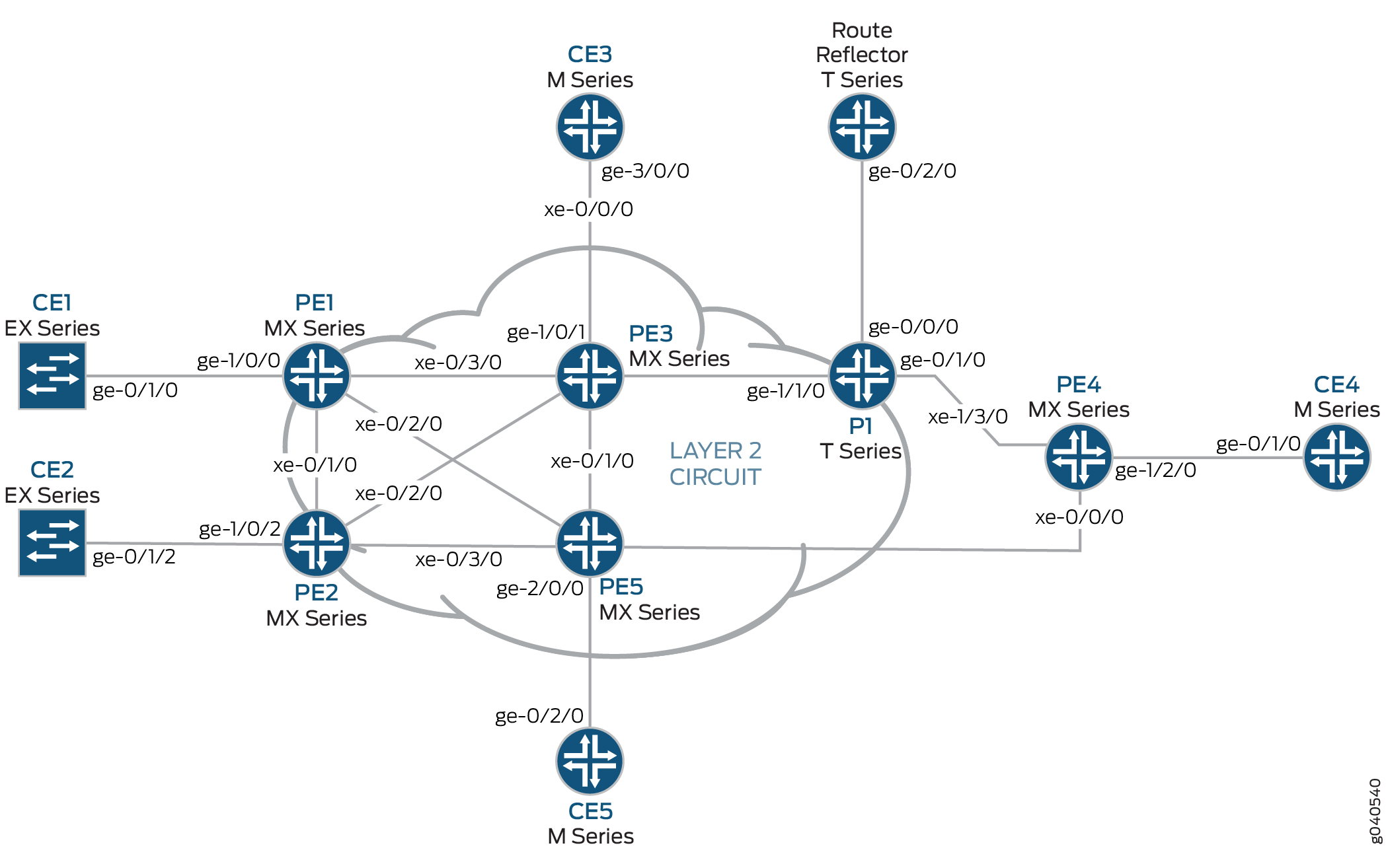 的物理拓扑
的物理拓扑
第 2 层 VPN 到第 3 层 VPN 互连的逻辑拓扑如 图 2 所示。
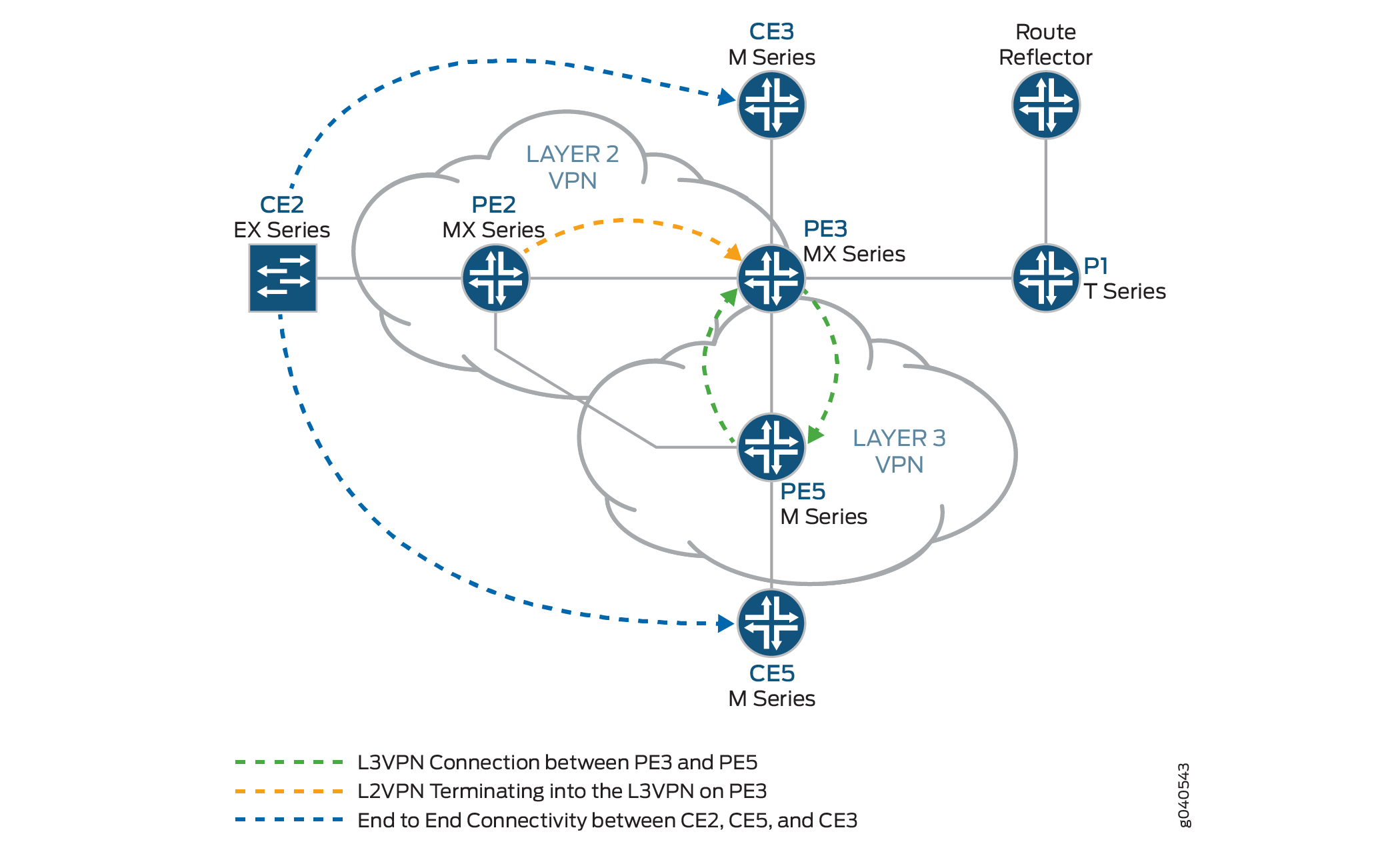 的逻辑拓扑
的逻辑拓扑
以下定义描述了 图 1 和 图 2 中使用的设备缩写的含义。
客户边缘 (CE) 设备 — 客户内部的一种设备,可通过与一个或多个提供商边缘 (PE) 路由器的数据链路提供对服务提供商 VPN 的访问。
通常,CE 设备是一个与其直接连接的 PE 路由器建立邻接关系的 IP 路由器。建立邻接关系后,CE 路由器会将站点的本地 VPN 路由播发至 PE 路由器,并从 PE 路由器学习远程 VPN 路由。
提供商边缘 (PE) 设备 — 位于提供商网络边缘的一台或一组设备,可显示提供商对客户站点的视图。
PE 路由器与 CE 路由器交换路由信息。PE 路由器会意识到通过这些 VPN 进行连接,并且 PE 路由器会维护 VPN 状态。PE 路由器只需为维护其直接连接的 VPN 的 VPN 路由。PE 路由器从 CE 路由器学习本地 VPN 路由后,即可使用 IBGP 与其他 PE 路由器交换 VPN 路由信息。最后,当使用 MPLS 跨提供商的骨干网转发 VPN 数据流量时,入口 PE 路由器充当入口标签交换路由器 (LSR),出口 PE 路由器则充当出口 LSR。
提供商 (P) 设备 — 在提供商的核心网络内运行且不直接连接到任何 CE 的设备。
尽管 P 设备是为服务提供商的客户实施 VPN 的关键部分,并且可以为属于不同 VPN 的许多提供商作的隧道提供路由,但它本身并不具备 VPN 感知能力,也不会维护 VPN 状态。它的主要作用是允许服务提供商扩展其 VPN 产品,例如,通过充当多个 PE 路由器的聚合点。
在 PE 路由器之间转发 VPN 数据流量时,P 路由器充当 MPLS 传输 LSR。P 路由器只需维护到提供商 PE 路由器的路由;他们不需要为每个客户站点维护特定的 VPN 路由信息。
配置
要将第 2 层 VPN 与第 3 层 VPN 互连,请执行以下任务:
配置基本协议和接口
分步过程
在每个 PE 和 P 路由器上,在所有接口上使用流量工程扩展配置 OSPF。在 fxp0.0 接口上禁用 OSPF。
[edit protocols]
ospf {
    traffic-engineering;
    area 0.0.0.0 {
        interface all;
        interface fxp0.0 {
            disable;
        }
    }
}
在所有核心路由器上,在所有接口上启用 MPLS。在 fxp0.0 接口上禁用 MPLS。
[edit protocols]
mpls {
    interface all;
    interface fxp0.0 {
        disable;
    }
}
在所有核心路由器上,创建内部 BGP 对等体组,并将路由反射器地址 (192.0.2.7) 指定为邻接方。此外,
signaling通过在[edit protocols bgp group group-name family l2vpn]层次结构级别包含语句,使 BGP 能够为此对等组传输第 2 层 VPLS 网络层可达性信息 (NLRI) 消息。[edit protocols] bgp { group RR { type internal; local-address 192.0.2.2; family l2vpn { signaling; } neighbor 192.0.2.7; } }在路由器 PE3 上,创建内部 BGP 对等体组,并将路由反射器 IP 地址 (192.0.2.7) 指定为邻接方。启用 BGP 以便此对等组携带第 2 层 VPLS NLRI 消息,并通过在
[edit protocols bgp group group-name family inet-vpn]层次结构级别包含unicast语句来启用 VPN-IPv4 地址的处理。[edit protocols] bgp { group RR { type internal; local-address 192.0.2.3; family inet-vpn { unicast; } family l2vpn { signaling; } neighbor 192.0.2.7; } }对于路由器 PE3 和路由器 PE5 上的第 3 层 VPN 域,请在所有接口上启用 RSVP。在 fxp0.0 接口上禁用 RSVP。
[edit protocols]
rsvp {
    interface all;
    interface fxp0.0 {
        disable;
    }
}
在路由器 PE3 和路由器 PE5 上,创建到路由反射器和其他 PE 路由器的标签交换路径 (LSP)。以下示例显示了路由器 PE5 上的配置。
[edit protocols]
mpls {
    label-switched-path to-RR {
        to 192.0.2.7;
    }
    label-switched-path to-PE2 {
        to 192.0.2.2;
    }
    label-switched-path to-PE3 {
        to 192.0.2.3;
    }
    label-switched-path to-PE4 {
        to 192.0.2.4;
    }
    label-switched-path to-PE1 {
        to 192.0.2.1;
    }
}
在路由器 PE1、PE2、PE3 和 PE5 上,使用 IPv4 地址配置核心接口并启用 MPLS 地址族。以下示例显示了路由器 PE2 上 xe-0/1/0 接口的配置。
[edit]
interfaces {
    xe-0/1/0 {
        unit 0 {
            family inet {
                address 10.10.2.2/30;
            }
            family mpls;
        }
    }
}
在路由器 PE2 和路由器 PE3 上,为所有接口的第 2 层 VPN MPLS 信令协议配置 LDP。在 fxp0.0 接口上禁用 LDP。(也可以使用 RSVP。
[edit protocols]
ldp {
    interface all;
    interface fxp0.0 {
        disable;
    }
}
在路由反射器上,创建内部 BGP 对等体组,并将 PE 路由器的 IP 地址指定为邻接方。
[edit]
protocols {
    bgp {
        group RR {
            type internal;
            local-address 192.0.2.7;
            family inet {
                unicast;
            }
            family inet-vpn {
                unicast;
            }
            family l2vpn {
                signaling;
            }
            cluster 192.0.2.7;
            neighbor 192.0.2.1;
            neighbor 192.0.2.2;
            neighbor 192.0.2.4;
            neighbor 192.0.2.5;
            neighbor 192.0.2.3;
        }
    }
}
在路由反射器上,配置面向路由器 PE3 和 PE5 的 MPLS LSP,以解析来自 inet.3 路由表的 BGP 下一跃点。
[edit]
protocols {
    mpls {
        label-switched-path to-pe3 {
            to 192.0.2.3;
        }

        label-switched-path to-pe5 {
            to 192.0.2.5;
        }
        interface all;
    }
}
配置 VPN 接口
分步过程
路由器 PE2 是第 2 层 VPN 的一端。路由器 PE3 正在第 2 层 VPN 和第 3 层 VPN 之间执行第 2 层 VPN 拼接。路由器 PE3 使用逻辑隧道接口(lt 接口),该接口在两个不同的第 2 层 VPN 实例下应用了不同的逻辑接口单元。数据包通过路由器 PE3 上配置的 lt 接口进行循环。路由器 PE5 的配置包含 PE-CE 接口。
在路由器 PE2 上,配置 ge-1/0/2 接口封装。包括 encapsulation 语句,并在
[edit interfaces ge-1/0/2]层次结构级别指定ethernet-ccc选项(vlan-ccc也支持封装)。在整个第 2 层 VPN 域(路由器 PE2 和 PE3)中,封装应相同。另外,配置接口 lo0。[edit] interfaces { ge-1/0/2 { encapsulation ethernet-ccc; unit 0; } lo0 { unit 0 { family inet { address 192.0.2.2/24; } } } }在路由器 PE2 上,在 [
edit routing-instances]层次结构级别配置路由实例。此外,在 [edit routing-instances routing-instances-name protocols]层级配置第 2 层 VPN 协议。将远程站点 ID 配置为 3。站点 ID 3 表示路由器 PE3 (Hub-PE)。第 2 层 VPN 使用 LDP 作为信令协议。请注意,在以下示例中,路由实例和协议都命名为l2vpn。[edit] routing-instances {l2vpn{ # routing instance instance-type l2vpn; interface ge-1/0/2.0; route-distinguisher 65000:2; vrf-target target:65000:2; protocols {l2vpn{ # protocol encapsulation-type ethernet; site CE2 { site-identifier 2; interface ge-1/0/2.0 { remote-site-id 3; } } } } } }在路由器 PE5 上,为 PE-CE 链路
ge-2/0/0配置千兆以太网接口并配置lo0接口。[edit interfaces] ge-2/0/0 { unit 0 { family inet { address 198.51.100.8/24; } } } lo0 { unit 0 { } }在路由器 PE5 上,在
[edit routing-instances]层次结构级别配置第 3 层 VPN 路由实例 (L3VPN)。还要在[edit routing-instances L3VPN protocols]层次结构级别配置 BGP。[edit] routing-instances { L3VPN { instance-type vrf; interface ge-2/0/0.0; route-distinguisher 65000:5; vrf-target target:65000:2; vrf-table-label; protocols { bgp { group ce5 { neighbor 198.51.100.2 { peer-as 200; } } } } } }在 MX 系列路由器(如路由器 PE3)中,您必须创建用于隧道服务的通道服务接口。要创建隧道服务接口,请包含
bandwidth该语句,并指定在[edit chassis fpc slot-number pic slot-number tunnel-services]层次结构级别上为隧道服务保留的带宽量(以千兆位/秒为单位)。[edit] chassis { dump-on-panic; fpc 1 { pic 1 { tunnel-services { bandwidth 1g; } } } }在路由器 PE3 上,配置千兆以太网接口。
在
[edit interfaces ge-1/0/1.0 family inet]层次结构级别包含address语句并指定198.51.100.9/24为 IP 地址。[edit] interfaces { ge-1/0/1 { unit 0 { family inet { address 198.51.100.9/24; } } } }在路由器 PE3 上,在
[edit interfaces lt-1/1/10 unit 0]层次结构级别配置lt-1/1/10.0逻辑隧道接口。路由器 PE3 是使用逻辑隧道接口将第 2 层 VPN 拼接到第 3 层 VPN 的路由器。对等单元接口的配置是实现互连的原因。要配置接口,请包含
encapsulation语句并指定ethernet-ccc选项。包含peer-unit语句并将逻辑接口单元1指定为对等隧道接口。包括family语句并指定ccc选项。[edit] interfaces { lt-1/1/10 { unit 0 { encapsulation ethernet-ccc; peer-unit 1; family ccc; } } }在路由器 PE3 上,在
[edit interfaces lt-1/1/10 unit 1]层次结构级别配置lt-1/1/10.1逻辑隧道接口。要配置接口,请包含
encapsulation语句并指定ethernet选项。包含peer-unit语句并将逻辑接口单元0指定为对等隧道接口。包括family语句并指定inet选项。在[edit interfaces lt-1/1/10 unit 0]层次结构级别包含address语句并指定198.51.100.7/24为 IPv4 地址。[edit] interfaces { lt-1/1/10 { unit 1 { encapsulation ethernet; peer-unit 0; family inet { address 198.51.100.7/24; } } } }在路由器 PE3 上,将接口单元 1 添加到
lt层级的路由实例[edit routing-instances L3VPN]。将实例类型配置为vrfltPE-CE 接口,将路由器 PE2 上的第 2 层 VPN 终止为路由器 PE3 上的第 3 层 VPN。[edit] routing-instances { L3VPN { instance-type vrf; interface ge-1/0/1.0; interface lt-1/1/10.1; route-distinguisher 65000:33; vrf-target target:65000:2; vrf-table-label; protocols { bgp { export direct; group ce3 { neighbor 198.51.100.10 { peer-as 100; } } } } } }在路由器 PE3 上,将接口单元 0 添加到
lt层级的路由实例[edit routing-instances protocols l2vpn]。还要为第 2 层 VPN 和第 3 层 VPN 路由实例配置相同的 vrf 目标,以便在实例之间泄露路由。上一步中的示例配置显示了路由实例的L3VPNvrf 目标。以下示例显示了路由实例的l2vpnvrf 目标。[edit] routing-instances { l2vpn { instance-type l2vpn; interface lt-1/1/10.0; route-distinguisher 65000:3; vrf-target target:65000:2; protocols { l2vpn { encapsulation-type ethernet; site CE3 { site-identifier 3; interface lt-1/1/10.0 { remote-site-id 2; } } } } } }在路由器 PE3 上,配置
policy-statement语句以将从直接连接lt的接口单元 1 获知的路由导出到所有 CE 路由器以进行连接(如果需要)。[edit] policy-options { policy-statement direct { term 1 { from protocol direct; then accept; } } }
结果
以下输出显示了路由器 PE2 的完整配置:
路由器 PE2
interfaces {
    xe-0/1/0 {
        unit 0 {
            family inet {
                address 10.10.2.2/30;
            }
            family mpls;
        }
    }
    xe-0/2/0 {
        unit 0 {
            family inet {
                address 10.10.5.1/30;
            }
            family mpls;
        }
    }
    xe-0/3/0 {
        unit 0 {
            family inet {
                address 10.10.4.1/30;
            }
            family mpls;
        }
    }
    ge-1/0/2 {
        encapsulation ethernet-ccc;
        unit 0;
    }
    fxp0 {
        apply-groups [ re0 re1 ];
    }
    lo0 {
        unit 0 {
            family inet {
                address 192.0.2.2/24;
            }
        }
    }
}
routing-options {
    static {
        route 172.0.0.0/8 next-hop 172.19.59.1;
    }
    autonomous-system 65000;
}
protocols {
    mpls {
        interface all;
        interface fxp0.0 {
            disable;
        }
    }
    bgp {
        group RR {
            type internal;
            local-address 192.0.2.2;
            family l2vpn {
                signaling;
            }
            neighbor 192.0.2.7;
        }
    }
    ospf {
        traffic-engineering;
        area 0.0.0.0 {
            interface all;
            interface fxp0.0 {
                disable;
            }
        }
    }
    ldp {
        interface all;
        interface fxp0.0 {
            disable;
        }
    }
}
routing-instances {
    l2vpn {
        instance-type l2vpn;
        interface ge-1/0/2.0;
        route-distinguisher 65000:2;
        vrf-target target:65000:2;
        protocols {
            l2vpn {
                encapsulation-type ethernet;
                site CE2 {
                    site-identifier 2;
                    interface ge-1/0/2.0 {
                        remote-site-id 3;
                    }
                }
            }
        }
    }
}
以下输出显示了路由器 PE5 的最终配置:
路由器 PE5
interfaces {
    ge-0/0/0 {
        unit 0 {
            family inet {
                address 10.10.4.2/30;
            }
            family mpls;
        }
    }
    xe-0/1/0 {
        unit 0 {
            family inet {
                address 10.10.6.2/30;
            }
            family mpls;
        }
    }
    ge-1/0/0 {
        unit 0 {
            family inet {
                address 10.10.9.1/30;
            }
            family mpls;
        }
    }
    xe-1/1/0 {
        unit 0 {
            family inet {
                address 10.10.3.2/30;
            }
            family mpls;
        }
    }
    ge-2/0/0 {
        unit 0 {
            family inet {
                address 198.51.100.8/24;
            }
        }
    }
    lo0 {
        unit 0 {
            family inet {
                address 192.0.2.5/24;
            }
        }
    }
}
routing-options {
    static {
        route 172.0.0.0/8 next-hop 172.19.59.1;
    }
    autonomous-system 65000;
}
protocols {
    rsvp {
        interface all {
            link-protection;
        }
        interface fxp0.0 {
            disable;
        }
    }
    mpls {
        label-switched-path to-RR {
            to 192.0.2.7;
        }
        label-switched-path to-PE2 {
            to 192.0.2.2;
        }
        label-switched-path to-PE3 {
            to 192.0.2.3;
        }
        label-switched-path to-PE4 {
            to 192.0.2.4;
        }
        label-switched-path to-PE1 {
            to 192.0.2.1;
        }
        interface all;
        interface fxp0.0 {
            disable;
        }

    }
    bgp {
        group to-rr {
            type internal;
            local-address 192.0.2.5;
            family inet-vpn {
                unicast;
            }
            family l2vpn {
                signaling;
            }
            neighbor 192.0.2.7;
        }
    }
    ospf {
        traffic-engineering;
        area 0.0.0.0 {
            interface all;
            interface fxp0.0 {
                disable;
            }
        }
    }
    ldp {
        interface all;
        interface fxp0.0 {
            disable;
        }
    }
}
routing-instances {
    L3VPN {
        instance-type vrf;
        interface ge-2/0/0.0;
        route-distinguisher 65000:5;
        vrf-target target:65000:2;
        vrf-table-label;
        protocols {
            bgp {
                group ce5 {
                    neighbor 198.51.100.2 {
                        peer-as 200;
                    }
                }
            }
        }
    }
}
以下输出显示了路由器 PE3 的最终配置:
路由器 PE3
chassis {
    dump-on-panic;
    fpc 1 {
        pic 1 {
            tunnel-services {
                bandwidth 1g;
            }
        }
    }
    network-services ip;
}
interfaces {
    ge-1/0/1 {
        unit 0 {
            family inet {
                address 198.51.100.9/24;
            }
        }
    }
    lt-1/1/10 {
        unit 0 {
            encapsulation ethernet-ccc;
            peer-unit 1;
            family ccc;
        }
        unit 1 {
            encapsulation ethernet;
            peer-unit 0;
            family inet {
                address 198.51.100.7/24;
            }
        }
    }
    xe-2/0/0 {
        unit 0 {
            family inet {
                address 10.10.20.2/30;
            }
            family mpls;
        }
    }
    xe-2/1/0 {
        unit 0 {
            family inet {
                address 10.10.6.1/30;
            }
            family mpls;
        }
    }
    xe-2/2/0 {
        unit 0 {
            family inet {
                address 10.10.5.2/30;
            }
            family mpls;
        }
    }
    xe-2/3/0 {
        unit 0 {
            family inet {
                address 10.10.1.2/30;
            }
            family mpls;
        }
    }
    lo0 {
        unit 0 {
            family inet {
                address 192.0.2.3/24;
            }
        }
    }
}
routing-options {
    static {
        route 172.0.0.0/8 next-hop 172.19.59.1;
    }
    autonomous-system 65000;
}
protocols {
    rsvp {
        interface all;
        interface fxp0.0 {
            disable;
        }
    }
    mpls {
        label-switched-path to-RR {
            to 192.0.2.7;
        }
        label-switched-path to-PE2 {
            to 192.0.2.2;
        }
        label-switched-path to-PE5 {
            to 192.0.2.5;
        }
        label-switched-path to-PE4 {
            to 192.0.2.4;
        }
        label-switched-path to-PE1 {
            to 192.0.2.1;
        }
        interface all;
        interface fxp0.0 {
            disable;
        }
    }
    bgp {
        group RR {
            type internal;
            local-address 192.0.2.3;
            family inet-vpn {
                unicast;
            }
            family l2vpn {
                signaling;
            }
            neighbor 192.0.2.7;
        }
    }
    ospf {
        traffic-engineering;
        area 0.0.0.0 {
            interface all;
            interface fxp0.0 {
                disable;
            }
        }
    }
    ldp {
        interface all;
        interface fxp0.0 {
            disable;
        }
    }
}
policy-options {
    policy-statement direct {
        term 1 {
            from protocol direct;
            then accept;
        }
    }
}
routing-instances {
    L3VPN {
        instance-type vrf;
        interface ge-1/0/1.0;
        interface lt-1/1/10.1;
        route-distinguisher 65000:33;
        vrf-target target:65000:2;
        vrf-table-label;
        protocols {
            bgp {
                export direct;
                group ce3 {
                    neighbor 198.51.100.10 {
                        peer-as 100;
                    }
                }
            }
        }
    }
    l2vpn {
        instance-type l2vpn;
        interface lt-1/1/10.0;
        route-distinguisher 65000:3;
        vrf-target target:65000:2;
        protocols {
            l2vpn {
                encapsulation-type ethernet;
                site CE3 {
                    site-identifier 3;
                    interface lt-1/1/10.0 {
                        remote-site-id 2;
                    }
                }
            }
        }
    }
}
验证
验证第 2 层 VPN 到第 3 层 VPN 互连:
验证路由器 PE2 VPN 接口
目的
检查第 2 层 VPN 是否已启动并在路由器 PE2 接口上工作,以及所有路由是否都在那里。
行动
show l2vpn connections使用命令验证路由器 PE3 的连接站点 ID 是否为 3,且状态是否为Up。user@PE2> show l2vpn connections Layer-2 VPN connections: Legend for connection status (St) EI -- encapsulation invalid NC -- interface encapsulation not CCC/TCC/VPLS EM -- encapsulation mismatch WE -- interface and instance encaps not same VC-Dn -- Virtual circuit down NP -- interface hardware not present CM -- control-word mismatch -> -- only outbound connection is up CN -- circuit not provisioned <- -- only inbound connection is up OR -- out of range Up -- operational OL -- no outgoing label Dn -- down LD -- local site signaled down CF -- call admission control failure RD -- remote site signaled down SC -- local and remote site ID collision LN -- local site not designated LM -- local site ID not minimum designated RN -- remote site not designated RM -- remote site ID not minimum designated XX -- unknown connection status IL -- no incoming label MM -- MTU mismatch MI -- Mesh-Group ID not available BK -- Backup connection ST -- Standby connection PF -- Profile parse failure PB -- Profile busy RS -- remote site standby Legend for interface status Up -- operational Dn -- down Instance: l2vpn Local site: CE2 (2) connection-site Type St Time last up # Up trans 3 rmt Up Jan 7 14:14:37 2010 1 Remote PE: 192.0.2.3, Negotiated control-word: Yes (Null) Incoming label: 800000, Outgoing label: 800001 Local interface: ge-1/0/2.0, Status: Up, Encapsulation: ETHERNETshow route table使用命令验证第 2 层 VPN 路由是否存在,以及是否有通过xe-0/2/0.0接口的下一跃点10.10.5.2。以下输出验证 l2vpn.l2vpn.0 表中是否存在第 2 层 VPN 路由。应为路由器 PE3 显示类似的输出。user@PE2> show route table l2vpn.l2vpn.0 l2vpn.l2vpn.0: 2 destinations, 2 routes (2 active, 0 holddown, 0 hidden) + = Active Route, - = Last Active, * = Both 65000:2:2:3/96 *[L2VPN/170/-101] 02:40:35, metric2 1 Indirect 65000:3:3:1/96 *[BGP/170] 02:40:35, localpref 100, from 192.0.2.7 AS path: I > to 10.10.5.2 via xe-0/2/0.0验证路由器 PE2 是否具有一个第 2 层 VPN MPLS 标签,该标签在两个方向(PUSH 和 POP)上都指向路由器 PE3 的 LDP 标签。
user@PE2> show route table mpls.0
 mpls.0: 13 destinations, 13 routes (13 active, 0 holddown, 0 hidden)
+ = Active Route, - = Last Active, * = Both

0                  *[MPLS/0] 1w3d 08:57:41, metric 1
                      Receive
1                  *[MPLS/0] 1w3d 08:57:41, metric 1
                      Receive
2                  *[MPLS/0] 1w3d 08:57:41, metric 1
                      Receive
300560             *[LDP/9] 19:45:53, metric 1
                    > to 10.10.2.1 via xe-0/1/0.0, Pop
300560(S=0)        *[LDP/9] 19:45:53, metric 1
                    > to 10.10.2.1 via xe-0/1/0.0, Pop
301008             *[LDP/9] 19:45:53, metric 1
                    > to 10.10.4.2 via xe-0/3/0.0, Swap 299856
301536             *[LDP/9] 19:45:53, metric 1
                    > to 10.10.4.2 via xe-0/3/0.0, Pop
301536(S=0)        *[LDP/9] 19:45:53, metric 1
                    > to 10.10.4.2 via xe-0/3/0.0, Pop
301712             *[LDP/9] 16:14:52, metric 1
                    > to 10.10.5.2 via xe-0/2/0.0, Swap 315184
301728             *[LDP/9] 16:14:52, metric 1
                    > to 10.10.5.2 via xe-0/2/0.0, Pop
301728(S=0)        *[LDP/9] 16:14:52, metric 1
                    > to 10.10.5.2 via xe-0/2/0.0, Pop
800000             *[L2VPN/7] 02:40:35
                    > via ge-1/0/2.0, Pop       Offset: 4
ge-1/0/2.0         *[L2VPN/7] 02:40:35, metric2 1
                    > to 10.10.5.2 via xe-0/2/0.0, Push 800001 Offset: -4
意义
l2vpn路由实例在接口ge-1/0/2上启动,第 2 层 VPN 路由如表 l2vpn.l2vpn.0 所示。表mpls.0显示了用于使用 LDP 标签转发流量的第 2 层 VPN 路由。
验证路由器 PE3 VPN 接口
目的
检查来自路由器 PE2 和路由器 PE3 的第 2 层 VPN 连接是否正常 Up 工作。
行动
验证是否已建立与家族
l2vpn-signaling和家族inet-vpn的路由反射器的 BGP 会话。user@PE3> show bgp summary Groups: 2 Peers: 2 Down peers: 0 Table Tot Paths Act Paths Suppressed History Damp State Pending bgp.l2vpn.0 1 1 0 0 0 0 bgp.L3VPN.0 1 1 0 0 0 0 Peer AS InPkt OutPkt OutQ Flaps Last Up/Dwn State|#Active /Received/Accepted/Damped... 192.0.2.7 65000 2063 2084 0 1 15:35:16 Establ bgp.l2vpn.0: 1/1/1/0 bgp.L3VPN.0: 1/1/1/0 L3VPN.inet.0: 1/1/1/0 l2vpn.l2vpn.0: 1/1/1/0
以下输出验证第 2 层 VPN 路由以及与之关联的标签。
user@PE3> show route table l2vpn.l2vpn.0 detail
l2vpn.l2vpn.0: 2 destinations, 2 routes (2 active, 0 holddown, 0 hidden)
65000:2:2:3/96 (1 entry, 1 announced)
        *BGP    Preference: 170/-101
                Route Distinguisher: 65000:2
                Next hop type: Indirect
                Next-hop reference count: 4
                Source: 192.0.2.7
                Protocol next hop: 192.0.2.2
                Indirect next hop: 2 no-forward
                State: <Secondary Active Int Ext>
                Local AS: 65000 Peer AS: 65000
                Age: 2:45:52    Metric2: 1
                Task: BGP_65000.192.0.2.7+60585
                Announcement bits (1): 0-l2vpn-l2vpn
                AS path: I (Originator) Cluster list:  192.0.2.7
                AS path:  Originator ID: 192.0.2.2
                Communities: target:65000:2 Layer2-info: encaps:ETHERNET, control flags:Control-Word, mtu: 0, site preference: 100  Accepted
                Label-base: 800000, range: 2, status-vector: 0x0
                Localpref: 100
                Router ID: 192.0.2.7
                Primary Routing Table bgp.l2vpn.0
以下输出显示 mpls.0 路由表中的 L2VPN MPLS.0 路由。
user@PE3> show route table mpls.0
mpls.0: 21 destinations, 21 routes (21 active, 0 holddown, 0 hidden)
+ = Active Route, - = Last Active, * = Both

0                  *[MPLS/0] 1w3d 09:05:41, metric 1
                      Receive
1                  *[MPLS/0] 1w3d 09:05:41, metric 1
                      Receive
2                  *[MPLS/0] 1w3d 09:05:41, metric 1
                      Receive
16                 *[VPN/0] 15:59:24
                      to table L3VPN.inet.0, Pop
315184             *[LDP/9] 16:21:53, metric 1
                    > to 10.10.20.1 via xe-2/0/0.0, Pop
315184(S=0)        *[LDP/9] 16:21:53, metric 1
                    > to 10.10.20.1 via xe-2/0/0.0, Pop
315200             *[LDP/9] 01:13:44, metric 1
                      to 10.10.20.1 via xe-2/0/0.0, Swap 625297
                    > to 10.10.6.2 via xe-2/1/0.0, Swap 299856
315216             *[LDP/9] 16:21:53, metric 1
                    > to 10.10.6.2 via xe-2/1/0.0, Pop
315216(S=0)        *[LDP/9] 16:21:53, metric 1
                    > to 10.10.6.2 via xe-2/1/0.0, Pop
315232             *[LDP/9] 16:21:45, metric 1
                    > to 10.10.1.1 via xe-2/3/0.0, Pop
315232(S=0)        *[LDP/9] 16:21:45, metric 1
                    > to 10.10.1.1 via xe-2/3/0.0, Pop
315248             *[LDP/9] 16:21:53, metric 1
                    > to 10.10.5.1 via xe-2/2/0.0, Pop
315248(S=0)        *[LDP/9] 16:21:53, metric 1
                    > to 10.10.5.1 via xe-2/2/0.0, Pop
315312             *[RSVP/7] 15:02:40, metric 1
                    > to 10.10.6.2 via xe-2/1/0.0, label-switched-path to-pe5
315312(S=0)        *[RSVP/7] 15:02:40, metric 1
                    > to 10.10.6.2 via xe-2/1/0.0, label-switched-path to-pe5
315328             *[RSVP/7] 15:02:40, metric 1
                    > to 10.10.20.1 via xe-2/0/0.0, label-switched-path to-RR
315360             *[RSVP/7] 15:02:40, metric 1
                    > to 10.10.20.1 via xe-2/0/0.0, label-switched-path to-RR
316272             *[RSVP/7] 01:13:27, metric 1
                    > to 10.10.6.2 via xe-2/1/0.0, label-switched-path Bypass->10.10.9.1
316272(S=0)        *[RSVP/7] 01:13:27, metric 1
                    > to 10.10.6.2 via xe-2/1/0.0, label-switched-path Bypass->10.10.9.1
800001             *[L2VPN/7] 02:47:33
                    > via lt-1/1/10.0, Pop       Offset: 4
lt-1/1/10.0        *[L2VPN/7] 02:47:33, metric2 1
                    > to 10.10.5.1 via xe-2/2/0.0, Push 800000 Offset: -4
使用带有
detail选项的命令show route table mpls.0可查看路由的 BGP 属性,例如下一跃点类型和标签作。user@PE5> show route table mpls.0 detail lt-1/1/10.0 (1 entry, 1 announced) *L2VPN Preference: 7 Next hop type: Indirect Next-hop reference count: 2 Next hop type: Router, Next hop index: 607 Next hop: 10.10.5.1 via xe-2/2/0.0, selected Label operation: Push 800000 Offset: -4 Protocol next hop: 192.0.2.2 Push 800000 Offset: -4 Indirect next hop: 8cae0a0 1048574 State: <Active Int> Age: 2:46:34 Metric2: 1 Task: Common L2 VC Announcement bits (2): 0-KRT 2-Common L2 VC AS path: I Communities: target:65000:2 Layer2-info: encaps:ETHERNET, control flags:Control-Word, mtu: 0, site preference: 100
验证从路由器 CE2 到路由器 CE5 和路由器 CE3 的端到端连接
目的
检查路由器 CE2、CE3 和 CE5 之间的连接。
行动
从路由器 CE2 对路由器 CE3 IP 地址执行 Ping 命令。
user@CE2> ping 198.51.100.10 # CE3 IP address
PING 198.51.100.10 (198.51.100.10): 56 data bytes
64 bytes from 198.51.100.10: icmp_seq=0 ttl=63 time=0.708 ms
64 bytes from 198.51.100.10: icmp_seq=1 ttl=63 time=0.610 ms
从路由器 CE2 对路由器 CE5 IP 地址执行 Ping 命令。
user@CE2> ping 198.51.100.2 # CE5 IP address
PING 198.51.100.2 (198.51.100.2): 56 data bytes
64 bytes from 198.51.100.2: icmp_seq=0 ttl=62 time=0.995 ms
64 bytes from 198.51.100.2: icmp_seq=1 ttl=62 time=1.005 ms