本页内容
LDP 配置
最低 LDP 配置
启用和禁用 LDP
配置 hello 消息的 LDP 计时器
LDP hello 消息使 LDP 节点能够相互发现,并检测邻接方故障或邻接方链路故障。Hello 消息会定期在启用了 LDP 的所有接口上发送。
LDP hello 消息有两种类型:
链路发送消息 — 通过 LDP 接口作为 UDP 数据包发送到 LDP 发现端口。在接口上收到 LDP 链路 hello 消息可识别与 LDP 对等路由器的邻接关系。
有针对性的 hello 消息 — 作为 UDP 数据包发送到特定地址的 LDP 发现端口。有针对性的 hello 消息用于支持未直接连接的路由器之间的 LDP 会话。目标路由器确定是响应还是忽略目标问候消息。选择响应的目标路由器通过定期将有针对性的 hello 消息发送回发起路由器来实现响应。
默认情况下,LDP 每 5 秒发送一次链路 hello 消息,每 15 秒发送一次目标 hello 消息。您可以配置 LDP 计时器来更改这两种类型的 hello 消息的发送频率。但是,不能为 LDP 计时器配置大于 LDP 保持时间的时间。有关更多信息,请参阅 配置 LDP 邻接方被视为关闭之前的延迟。
为链路发送消息配置 LDP 计时器
要修改 LDP 发送链路 hello 消息的频率,请使用以下 hello-interval 语句为 LDP 计时器指定新的链路 hello 消息间隔:
hello-interval seconds;
有关可包含此语句的层次结构级别列表,请参阅此语句的语句摘要部分。
为有针对性的 hello 消息配置 LDP 计时器
要修改 LDP 发送定向 hello 消息的频率,请将语 hello-interval 句配置为语句的 targeted-hello 选项,为 LDP 计时器指定新的定向 hello 消息间隔:
targeted-hello {
    hello-interval seconds;
}
有关可包含这些语句的层次结构级别列表,请参阅这些语句的语句摘要部分。
配置 LDP 邻接方被视为关闭之前的延迟
保持时间决定了 LDP 节点在宣布邻接方关闭之前应等待 hello 消息多长时间。此值作为 hello 消息的一部分发送,以便每个 LDP 节点告诉其邻接方等待多长时间。每个邻接方发送的值不必匹配。
等待时间通常应至少是 hello 间隔的三倍。链路 hello 消息的默认值为 15 秒,目标 hello 消息的默认值为 45 秒。但是,可以配置接近 hello 间隔值的 LDP 保持时间。
通过配置接近 hello 间隔(小于 hello 间隔的三倍)的 LDP 保持时间,可以更快地检测到 LDP 邻接方故障。但是,这也增加了路由器声明仍在正常运行的 LDP 邻接方关闭的可能性。有关更多信息,请参阅 配置 hello 消息的 LDP 计时器。
LDP 保持时间也会在 LDP 对等方之间自动协商。当两个 LDP 对等方相互播发不同的 LDP 保持时间时,将使用较小的值。如果 LDP 对等路由器播发的保持时间短于您配置的值,则使用对等路由器的播发保留时间。此协商也会影响 LDP 激活间隔。
如果在 LDP 对等方协商期间本地 LDP 保持时间未缩短,则用户配置的激活间隔将保持不变。但是,如果在对等协商期间本地保持时间减少,则会重新计算激活间隔。如果在对等协商期间缩短了 LDP 保持时间,则激活间隔将减少到新保持时间值的三分之一。例如,如果新的保持时间值为 45 秒,则激活间隔设置为 15 秒。
这种自动激活间隔计算可能会导致在每台对等路由器上配置不同的激活间隔。这使得路由器可以灵活发送激活消息的频率,因为 LDP 对等协商可确保发送消息的频率高于 LDP 保持时间。
重新配置保留时间间隔时,更改在会话重置之前不会生效。保留时间在 LDP 对等会话启动时协商,只要会话处于开启状态就无法重新协商(RFC 5036,LDP 规范要求)。要手动强制重置 LDP 会话,请发出命令 clear ldp session 。
配置链路发送消息的 LDP 保持时间
要修改 LDP 节点在宣布邻接方关闭之前应等待链路发送消息的时间,请使用以下 hold-time 语句指定一个新时间(以秒为单位):
hold-time seconds;
有关可包含此语句的层次结构级别列表,请参阅此语句的语句摘要部分。
配置目标 hello 消息的 LDP 保持时间
要修改 LDP 节点在宣布邻接方关闭之前应等待目标 hello 消息的时间,请使用 hold-time 该语句作为该语句的 targeted-hello 选项指定一个新时间(以秒为单位):
targeted-hello {
    hold-time seconds;
}
有关可包含这些语句的层次结构级别列表,请参阅这些语句的语句摘要部分。
为 LDP 启用严格的定向 hello 消息
使用严格有针对性的 hello 消息来防止与未经专门配置的远程邻接方建立 LDP 会话。如果配置该 strict-targeted-hellos 语句,则 LDP 对等方不会响应来自不属于其配置的远程邻接方之一的源的定向 hello 消息。配置的远程邻接方可以包括:
配置了 LDP 隧道的 RSVP 隧道的端点
第 2 层电路邻接方
如果未配置的邻接方发送 hello 消息,LDP 对等方将忽略该消息,并记录指示源的错误(带有 error 跟踪标志)。例如,如果 LDP 对等方收到来自互联网地址 10.0.0.1 的目标 hello,并且未专门配置使用此地址的邻接方,则会将以下消息打印到 LDP 日志文件中:
LDP: Ignoring targeted hello from 10.0.0.1
要启用严格的定向 hello 消息,请包含以下 strict-targeted-hellos 语句:
strict-targeted-hellos;
有关可包含此语句的层次结构级别列表,请参阅此语句的语句摘要部分。
配置 LDP 激活消息的间隔
激活间隔确定通过会话发送消息的频率,以确保不超过激活超时。如果在此时间内没有通过会话发送其他 LDP 流量,则会发送一条激活消息。默认设置为 10 秒。最小值为 1 秒。
如果在对等路由器上为 LDP 保持时间配置的值低于本地配置的值,则可以在 LDP 会话协商期间更改为保持连接间隔配置的值。有关更多信息,请参阅 配置 LDP 邻接方被视为关闭之前的延迟。
要修改激活间隔,请包含以下语 keepalive-interval 句:
keepalive-interval seconds;
有关可包含此语句的层次结构级别列表,请参阅此语句的语句摘要部分。
配置 LDP 激活超时
建立 LDP 会话后,必须定期交换消息,以确保会话仍在工作。激活超时定义了邻接方 LDP 节点在决定会话失败之前等待的时间长度。此值通常至少设置为激活间隔的三倍。默认设置为 30 秒。
要修改激活间隔,请包含以下语 keepalive-timeout 句:
keepalive-timeout seconds;
有关可包含此语句的层次结构级别列表,请参阅此语句的语句摘要部分。
发出命令时show ldp session detail,为语句配置keepalive-timeout的值将显示为保持时间。
为 LDP 配置最长匹配
为了让 LDP 能够学习域间跨OSPF区域或IS-IS级别汇总或汇总的路由,Junos OS允许您根据 RFC5283为 LDP 配置最长匹配。
为 LDP 配置最长匹配之前,必须执行以下操作:
配置设备接口。
配置 MPLS 协议。
配置 OSPF 协议。
要为 LDP 配置最长匹配,必须执行以下操作:
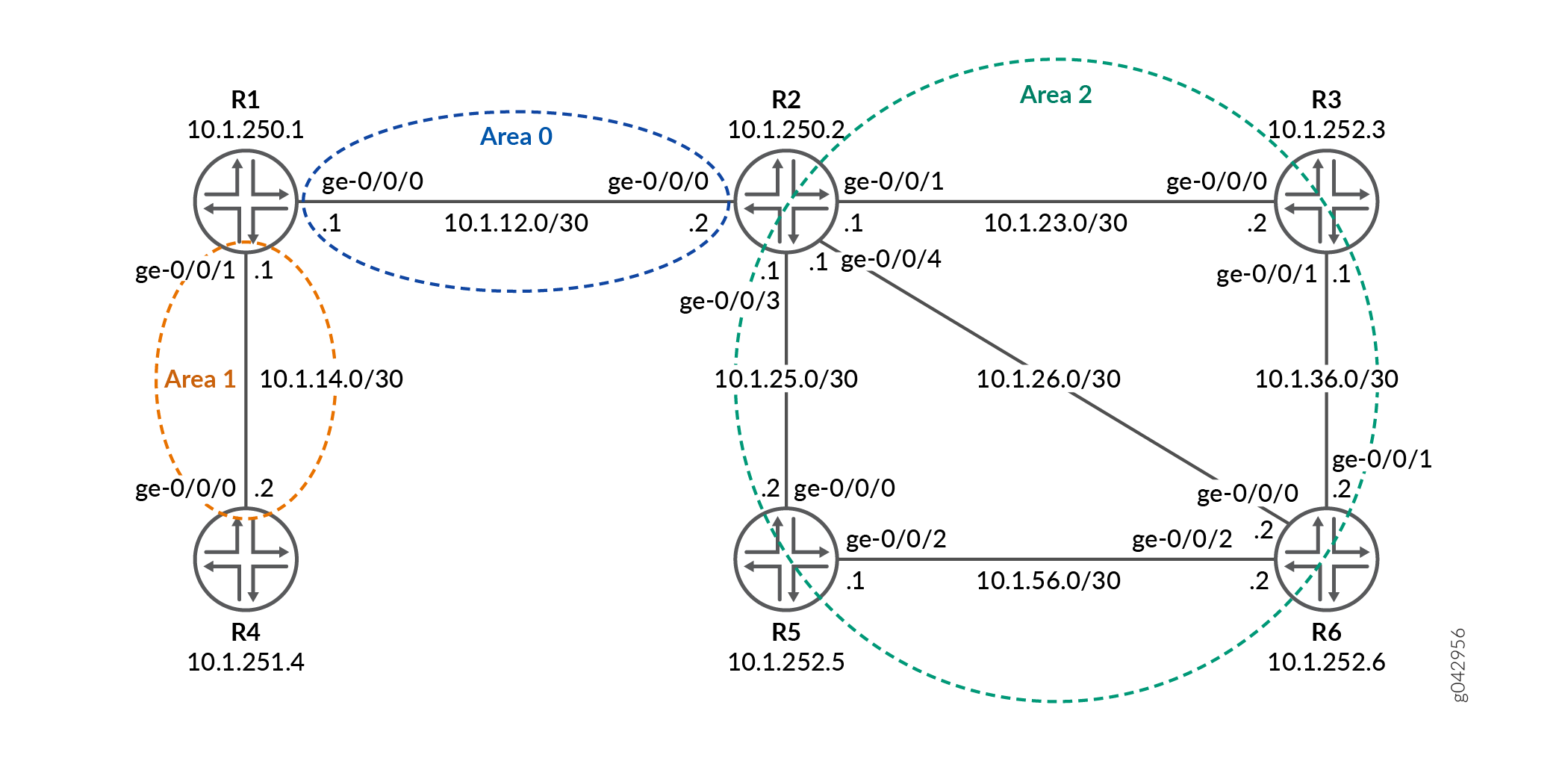
示例:为 LDP 配置最长匹配
此示例说明如何基于 RFC5283为 LDP 配置最长匹配。这使 LDP 能够学习跨 OSPF 区域或域间 IS-IS 级别汇总或汇总的路由。最长匹配策略提供按前缀粒度。
要求
此示例使用以下硬件和软件组件:
六台具有 OSPF 协议并在连接的接口上启用了 LDP 的 MX 系列路由器。
所有设备上运行 Junos OS 16.1 或更高版本。
开始之前:
配置设备接口。
配置 OSPF。
概述
LDP 通常用于使用 OSPF 或 IS-IS 等 IGP 在整个网域中建立 MPLS 标签交换路径 (LSP)。在此类网络中,域中的所有链路都具有 IGP 邻接和 LDP 邻接。LDP 在 IP 转发确定的到达目标的最短路径上建立 LSP。在 Junos OS 中,LDP 实施会对 RIB 或 IGP 路由中 FEC 的 IP 地址执行精确匹配查找,以进行标签映射。此精确映射需要在所有 LER 中配置 MPLS 端到端 LDP 端点 IP 地址。这违背了接入设备中 IP 分层设计或默认路由的目的。 longest-match 配置通过抑制精确匹配行为并根据每个前缀的最长匹配路由设置 LSP 来帮助克服这个问题。
配置
CLI 快速配置
要快速配置此示例,请复制以下命令,将其粘贴到文本文件中,删除所有换行符,更改详细信息,以便与网络配置匹配,将命令复制并粘贴到层次结构级别的 [edit] CLI 中,然后从配置模式进入。commit
R0
set interfaces ge-0/0/0 unit 0 family inet address 22.22.22.1/24
set interfaces ge-0/0/1 unit 0 family inet address 15.15.15.1/24
set interfaces ge-0/0/2 unit 0 family inet address 11.11.11.1/24
set interfaces ge-0/0/2 unit 0 family iso
set interfaces ge-0/0/2 unit 0 family mpls
set interfaces lo0 unit 0 family inet address 10.255.112.1/32 primary
set interfaces lo0 unit 0 family inet address 10.255.112.1/32 preferred
set interfaces lo0 unit 0 family iso address 49.0002.0192.0168.0001.00
set routing-options router-id 10.255.112.1
set protocols mpls interface ge-0/0/2.0
set protocols ospf area 0.0.0.1 interface ge-0/0/2.0
set protocols ospf area 0.0.0.1 interface lo0.0 passive
set protocols ldp longest-match
set protocols ldp interface ge-0/0/2.0
set protocols ldp interface lo0.0
R1
set interfaces ge-0/0/0 unit 0 family inet address 11.11.11.2/24
set interfaces ge-0/0/0 unit 0 family iso
set interfaces ge-0/0/0 unit 0 family mpls
set interfaces ge-0/0/1 unit 0 family inet address 12.12.12.1/24
set interfaces ge-0/0/1 unit 0 family iso
set interfaces ge-0/0/1 unit 0 family mpls
set interfaces lo0 unit 0 family inet address 10.255.112.2/32 primary
set interfaces lo0 unit 0 family inet address 10.255.112.2/32 preferred
set interfaces lo0 unit 0 family iso address 49.0002.0192.0168.0002.00
set routing-options router-id 10.255.112.2
set protocols mpls interface ge-0/0/0.0
set protocols mpls interface ge-0/0/1.0
set protocols ospf area 0.0.0.0 interface ge-0/0/1.0
set protocols ospf area 0.0.0.0 interface lo0.0 passive
set protocols ospf area 0.0.0.1 interface ge-0/0/0.0
set protocols ldp longest-match
set protocols ldp interface ge-0/0/0.0
set protocols ldp interface ge-0/0/1.0
set protocols ldp interface lo0.0
R2
set interfaces ge-0/0/0 unit 0 family inet address 24.24.24.1/24
set interfaces ge-0/0/0 unit 0 family iso
set interfaces ge-0/0/0 unit 0 family mpls
set interfaces ge-0/0/1 unit 0 family inet address 12.12.12.2/24
set interfaces ge-0/0/1 unit 0 family iso
set interfaces ge-0/0/1 unit 0 family mpls
set interfaces ge-0/0/2 unit 0 family inet address 23.23.23.1/24
set interfaces ge-0/0/2 unit 0 family iso
set interfaces ge-0/0/2 unit 0 family mpls
set interfaces ge-0/0/3 unit 0 family inet address 22.22.22.2/24
set interfaces ge-0/0/4 unit 0 family inet address 25.25.25.1/24
set interfaces ge-0/0/4 unit 0 family iso
set interfaces ge-0/0/4 unit 0 family mpls
set interfaces lo0 unit 0 family inet address 10.255.111.4/32 primary
set interfaces lo0 unit 0 family inet address 10.255.111.4/32 preferred
set interfaces lo0 unit 0 family iso address 49.0003.0192.0168.0003.00
set routing-options router-id 10.255.111.4
set protocols mpls interface ge-0/0/1.0
set protocols mpls interface ge-0/0/2.0
set protocols mpls interface ge-0/0/0.0
set protocols mpls interface ge-0/0/4.0
set protocols ospf area 0.0.0.0 interface ge-0/0/1.0
set protocols ospf area 0.0.0.0 interface lo0.0 passive
set protocols ospf area 0.0.0.2 area-range 10.255.111.0/24
set protocols ospf area 0.0.0.2 interface ge-0/0/2.0
set protocols ospf area 0.0.0.2 interface ge-0/0/0.0
set protocols ospf area 0.0.0.2 interface ge-0/0/4.0
set protocols ldp interface ge-0/0/0.0
set protocols ldp interface ge-0/0/1.0
set protocols ldp interface ge-0/0/2.0
set protocols ldp interface ge-0/0/4.0
set protocols ldp interface lo0.0
R3
set interfaces ge-0/0/0 unit 0 family inet address 35.35.35.1/24
set interfaces ge-0/0/0 unit 0 family iso
set interfaces ge-0/0/0 unit 0 family mpls
set interfaces ge-0/0/1 unit 0 family inet address 23.23.23.2/24
set interfaces ge-0/0/1 unit 0 family iso
set interfaces ge-0/0/1 unit 0 family mpls
set interfaces ge-0/0/2 unit 0 family inet address 34.34.34.1/24
set interfaces ge-0/0/2 unit 0 family iso
set interfaces ge-0/0/2 unit 0 family mpls
set interfaces lo0 unit 0 family inet address 10.255.111.1/32 primary
set interfaces lo0 unit 0 family inet address 10.255.111.1/32 preferred
set interfaces lo0 unit 0 family iso address 49.0003.0192.0168.0004.00
set routing-options router-id 10.255.111.1
set protocols mpls interface ge-0/0/1.0
set protocols ospf area 0.0.0.2 interface ge-0/0/1.0
set protocols ospf area 0.0.0.2 interface fxp0.0 disable
set protocols ospf area 0.0.0.2 interface lo0.0 passive
set protocols ldp interface ge-0/0/1.0
set protocols ldp interface lo0.0
R4
set interfaces ge-0/0/0 unit 0 family inet address 45.45.45.1/24
set interfaces ge-0/0/0 unit 0 family iso
set interfaces ge-0/0/0 unit 0 family mpls
set interfaces ge-0/0/1 unit 0 family inet address 24.24.24.2/24
set interfaces ge-0/0/1 unit 0 family iso
set interfaces ge-0/0/1 unit 0 family mpls
set interfaces ge-0/0/2 unit 0 family inet address 34.34.34.2/24
set interfaces ge-0/0/2 unit 0 family iso
set interfaces ge-0/0/2 unit 0 family mpls
set interfaces lo0 unit 0 family inet address 10.255.111.2/32 primary
set interfaces lo0 unit 0 family inet address 10.255.111.2/32 preferred
set interfaces lo0 unit 0 family iso address 49.0003.0192.0168.0005.00
set routing-options router-id 10.255.111.2
set protocols mpls interface ge-0/0/1.0
set protocols ospf area 0.0.0.2 interface ge-0/0/1.0
set protocols ospf area 0.0.0.2 interface fxp0.0 disable
set protocols ospf area 0.0.0.2 interface lo0.0 passive
set protocols ldp interface ge-0/0/1.0
set protocols ldp interface lo0.0
R5
set interfaces ge-0/0/0 unit 0 family inet address 25.25.25.2/24
set interfaces ge-0/0/0 unit 0 family iso
set interfaces ge-0/0/0 unit 0 family mpls
set interfaces ge-0/0/1 unit 0 family inet address 15.15.15.2/24
set interfaces ge-0/0/2 unit 0 family inet address 35.35.35.2/24
set interfaces ge-0/0/3 unit 0 family inet address 45.45.45.2/24
set interfaces ge-0/0/3 unit 0 family iso
set interfaces ge-0/0/3 unit 0 family mpls
set interfaces lo0 unit 0 family inet address 10.255.111.3/32 primary
set interfaces lo0 unit 0 family inet address 10.255.111.3/32 preferred
set interfaces lo0 unit 0 family iso address 49.0003.0192.0168.0006.00
set routing-options router-id 10.255.111.3
set protocols mpls interface ge-0/0/0.0
set protocols ospf area 0.0.0.2 interface ge-0/0/0.0
set protocols ospf area 0.0.0.2 interface fxp0.0 disable
set protocols ospf area 0.0.0.2 interface lo0.0 passive
set protocols ldp interface ge-0/0/0.0
set protocols ldp interface lo0.0
配置设备 R0
分步程序
下面的示例要求您在各个配置层级中进行导航。有关导航 CLI 的信息,请参阅 《CLI 用户指南》中的在配置模式下使用 CLI 编辑器。
要配置设备 R0:
配置接口。
[edit interfaces]
set ge-0/0/0 unit 0 family inet address 22.22.22.1/24
set ge-0/0/1 unit 0 family inet address 15.15.15.1/24
set ge-0/0/2 unit 0 family inet address 11.11.11.1/24
set ge-0/0/2 unit 0 family iso
set ge-0/0/2 unit 0 family mpls
将环路地址分配给设备。
[edit interfaces lo0 unit 0 family]
set inet address 10.255.112.1/32 primary
set inet address 10.255.112.1/32 preferred
set iso address 49.0002.0192.0168.0001.00
配置路由器 ID。
[edit routing-options]
set router-id 10.255.112.1
在接口上配置 MPLS 协议。
[edit protocols mpls]
set interface ge-0/0/2.0
在接口上配置 OSPF 协议。
[edit protocols ospf]
set area 0.0.0.1 interface ge-0/0/2.0
set area 0.0.0.1 interface lo0.0 passive
为 LDP 协议配置最长匹配。
[edit protocols ldp]
set longest-match
在接口上配置 LDP 协议。
[edit protocols ldp]
set interface ge-0/0/2.0
set interface lo0.0
结果
在配置模式下,输入 show interfaces、 show protocols和 show routing-options 命令以确认您的配置。如果输出未显示预期的配置,请重复此示例中的说明以更正配置。
user@R0# show interfaces
ge-0/0/0 {
    unit 0 {
        family inet {
            address 22.22.22.1/24;
        }
    }
}
ge-0/0/1 {
    unit 0 {
        family inet {
            address 15.15.15.1/24;
        }
    }
}
ge-0/0/2 {
    unit 0 {
        family inet {
            address 11.11.11.1/24;
        }
        family iso;
        family mpls;
    }
}
lo0 {
    unit 0 {
        family inet {
            address 10.255.112.1/32 {
                primary;
                preferred;
            }
        }
        family iso {
            address 49.0002.0192.0168.0001.00;
        }
    }
}
user@R0# show protocols
mpls {
    interface ge-0/0/2.0;
}
ospf {
    area 0.0.0.1 {
        interface ge-0/0/2.0;
        interface lo0.0 {
            passive;
        }
    }
}
ldp {
    longest-match;
    interface ge-0/0/2.0;
    interface lo0.0;
}
user@R0# show routing-options
router-id 10.255.112.1;
如果完成设备配置,请从配置模式进入 commit 。
验证
确认配置工作正常。
验证路由
目的
验证是否已学习预期路由。
行动
在设备 R0 上,在操作模式下,运行 show route 命令以显示路由表中的路由。
user@R0> show route

inet.0: 62 destinations, 62 routes (62 active, 0 holddown, 0 hidden)
+ = Active Route, - = Last Active, * = Both

10.4.0.0/16        *[Static/5] 10:08:01
                    > to 10.92.31.254 via fxp0.0
10.5.0.0/16        *[Static/5] 10:08:01
                    > to 10.92.31.254 via fxp0.0
10.6.128.0/17      *[Static/5] 10:08:01
                    > to 10.92.31.254 via fxp0.0
10.9.0.0/16        *[Static/5] 10:08:01
                    > to 10.92.31.254 via fxp0.0
10.10.0.0/16       *[Static/5] 10:08:01
                    > to 10.92.31.254 via fxp0.0
10.13.4.0/23       *[Static/5] 10:08:01
                    > to 10.92.31.254 via fxp0.0
10.13.10.0/23      *[Static/5] 10:08:01
                    > to 10.92.31.254 via fxp0.0
10.82.0.0/15       *[Static/5] 10:08:01
                    > to 10.92.31.254 via fxp0.0
10.84.0.0/16       *[Static/5] 10:08:01
                    > to 10.92.31.254 via fxp0.0
10.85.12.0/22      *[Static/5] 10:08:01
                    > to 10.92.31.254 via fxp0.0
10.92.0.0/16       *[Static/5] 10:08:01
                    > to 10.92.31.254 via fxp0.0
10.92.16.0/20      *[Direct/0] 10:08:01
                    > via fxp0.0
10.92.20.175/32    *[Local/0] 10:08:01
                      Local via fxp0.0
10.94.0.0/16       *[Static/5] 10:08:01
                    > to 10.92.31.254 via fxp0.0
10.99.0.0/16       *[Static/5] 10:08:01
                    > to 10.92.31.254 via fxp0.0
10.102.0.0/16      *[Static/5] 10:08:01
                    > to 10.92.31.254 via fxp0.0
10.150.0.0/16      *[Static/5] 10:08:01
                    > to 10.92.31.254 via fxp0.0
10.155.0.0/16      *[Static/5] 10:08:01
                    > to 10.92.31.254 via fxp0.0
10.157.64.0/19     *[Static/5] 10:08:01
                    > to 10.92.31.254 via fxp0.0
10.160.0.0/16      *[Static/5] 10:08:01
                    > to 10.92.31.254 via fxp0.0
10.204.0.0/16      *[Static/5] 10:08:01
                    > to 10.92.31.254 via fxp0.0
10.205.0.0/16      *[Static/5] 10:08:01
                    > to 10.92.31.254 via fxp0.0
10.206.0.0/16      *[Static/5] 10:08:01
                    > to 10.92.31.254 via fxp0.0
10.207.0.0/16      *[Static/5] 10:08:01
                    > to 10.92.31.254 via fxp0.0
10.209.0.0/16      *[Static/5] 10:08:01
                    > to 10.92.31.254 via fxp0.0
10.212.0.0/16      *[Static/5] 10:08:01
                    > to 10.92.31.254 via fxp0.0
10.213.0.0/16      *[Static/5] 10:08:01
                    > to 10.92.31.254 via fxp0.0
10.214.0.0/16      *[Static/5] 10:08:01
                    > to 10.92.31.254 via fxp0.0
10.215.0.0/16      *[Static/5] 10:08:01
                    > to 10.92.31.254 via fxp0.0
10.216.0.0/16      *[Static/5] 10:08:01
                    > to 10.92.31.254 via fxp0.0
10.218.13.0/24     *[Static/5] 10:08:01
                    > to 10.92.31.254 via fxp0.0
10.218.14.0/24     *[Static/5] 10:08:01
                    > to 10.92.31.254 via fxp0.0
10.218.16.0/20     *[Static/5] 10:08:01
                    > to 10.92.31.254 via fxp0.0
10.218.32.0/20     *[Static/5] 10:08:01
                    > to 10.92.31.254 via fxp0.0
10.227.0.0/16      *[Static/5] 10:08:01
                    > to 10.92.31.254 via fxp0.0
10.255.111.0/24    *[OSPF/10] 09:52:14, metric 3
                    > to 11.11.11.2 via ge-0/0/2.0
10.255.111.4/32    *[OSPF/10] 09:54:10, metric 2
                    > to 11.11.11.2 via ge-0/0/2.0
10.255.112.1/32    *[Direct/0] 09:55:05
                    > via lo0.0
10.255.112.2/32    *[OSPF/10] 09:54:18, metric 1
                    > to 11.11.11.2 via ge-0/0/2.0
11.11.11.0/24      *[Direct/0] 09:55:05
                    > via ge-0/0/2.0
11.11.11.1/32      *[Local/0] 09:55:05
                      Local via ge-0/0/2.0
12.12.12.0/24      *[OSPF/10] 09:54:18, metric 2
                    > to 11.11.11.2 via ge-0/0/2.0
15.15.15.0/24      *[Direct/0] 09:55:05
                    > via ge-0/0/1.0
15.15.15.1/32      *[Local/0] 09:55:05
                      Local via ge-0/0/1.0
22.22.22.0/24      *[Direct/0] 09:55:05
                    > via ge-0/0/0.0
22.22.22.1/32      *[Local/0] 09:55:05
                      Local via ge-0/0/0.0
23.23.23.0/24      *[OSPF/10] 09:54:10, metric 3
                    > to 11.11.11.2 via ge-0/0/2.0
24.24.24.0/24      *[OSPF/10] 09:54:10, metric 3
                    > to 11.11.11.2 via ge-0/0/2.0
25.25.25.0/24      *[OSPF/10] 09:54:10, metric 3
                    > to 11.11.11.2 via ge-0/0/2.0
128.92.17.45/32    *[OSPF/10] 09:54:05, metric 3
                    > to 11.11.11.2 via ge-0/0/2.0
128.92.20.175/32   *[Direct/0] 10:08:01
                    > via lo0.0
128.92.21.186/32   *[OSPF/10] 09:54:10, metric 3
                    > to 11.11.11.2 via ge-0/0/2.0
128.92.25.135/32   *[OSPF/10] 09:54:10, metric 3
                    > to 11.11.11.2 via ge-0/0/2.0
128.92.27.91/32    *[OSPF/10] 09:54:18, metric 1
                    > to 11.11.11.2 via ge-0/0/2.0
128.92.28.70/32    *[OSPF/10] 09:54:10, metric 2
                    > to 11.11.11.2 via ge-0/0/2.0
172.16.0.0/12      *[Static/5] 10:08:01
                    > to 10.92.31.254 via fxp0.0
192.168.0.0/16     *[Static/5] 10:08:01
                    > to 10.92.31.254 via fxp0.0
192.168.102.0/23   *[Static/5] 10:08:01
                    > to 10.92.31.254 via fxp0.0
207.17.136.0/24    *[Static/5] 10:08:01
                    > to 10.92.31.254 via fxp0.0
207.17.136.192/32  *[Static/5] 10:08:01
                    > to 10.92.31.254 via fxp0.0
207.17.137.0/24    *[Static/5] 10:08:01
                    > to 10.92.31.254 via fxp0.0
224.0.0.5/32       *[OSPF/10] 09:55:05, metric 1
                      MultiRecv

inet.3: 5 destinations, 5 routes (5 active, 0 holddown, 0 hidden)
+ = Active Route, - = Last Active, * = Both

10.255.111.1/32    *[LDP/9] 09:41:03, metric 3
                    > to 11.11.11.2 via ge-0/0/2.0, Push 300128
10.255.111.2/32    *[LDP/9] 09:41:03, metric 3
                    > to 11.11.11.2 via ge-0/0/2.0, Push 300144
10.255.111.3/32    *[LDP/9] 09:41:03, metric 3
                    > to 11.11.11.2 via ge-0/0/2.0, Push 300160
10.255.111.4/32    *[LDP/9] 09:54:10, metric 2, tag 0
                    > to 11.11.11.2 via ge-0/0/2.0, Push 300000
10.255.112.2/32    *[LDP/9] 09:54:48, metric 1, tag 0
                    > to 11.11.11.2 via ge-0/0/2.0

iso.0: 2 destinations, 2 routes (2 active, 0 holddown, 0 hidden)
+ = Active Route, - = Last Active, * = Both

47.0005.80ff.f800.0000.0108.0001.1280.9202.0175/152
                   *[Direct/0] 10:08:01
                    > via lo0.0
49.0002.0192.0168.0001/72
                   *[Direct/0] 09:55:05
                    > via lo0.0

mpls.0: 10 destinations, 10 routes (10 active, 0 holddown, 0 hidden)
+ = Active Route, - = Last Active, * = Both

0                  *[MPLS/0] 09:55:05, metric 1
                      Receive
1                  *[MPLS/0] 09:55:05, metric 1
                      Receive
2                  *[MPLS/0] 09:55:05, metric 1
                      Receive
13                 *[MPLS/0] 09:55:05, metric 1
                      Receive
300064             *[LDP/9] 09:54:48, metric 1
                    > to 11.11.11.2 via ge-0/0/2.0, Pop
300064(S=0)        *[LDP/9] 09:54:48, metric 1
                    > to 11.11.11.2 via ge-0/0/2.0, Pop
300112             *[LDP/9] 09:54:10, metric 2, tag 0
                    > to 11.11.11.2 via ge-0/0/2.0, Swap 300000
300192             *[LDP/9] 09:41:03, metric 3
                    > to 11.11.11.2 via ge-0/0/2.0, Swap 300128
300208             *[LDP/9] 09:41:03, metric 3
                    > to 11.11.11.2 via ge-0/0/2.0, Swap 300144
300224             *[LDP/9] 09:41:03, metric 3
                    > to 11.11.11.2 via ge-0/0/2.0, Swap 300160

inet6.0: 2 destinations, 2 routes (2 active, 0 holddown, 0 hidden)
+ = Active Route, - = Last Active, * = Both

abcd::128:92:20:175/128
                   *[Direct/0] 10:08:01
                    > via lo0.0
fe80::5668:a50f:fcc1:1f9c/128
                   *[Direct/0] 10:08:01
                    > via lo0.0
意义
输出显示设备 R0 路由表中的所有路由。
验证 LDP 概述信息
目的
显示 LDP 概述信息。
行动
在设备 R0 上,在操作模式下,运行 show ldp overview 命令以显示 LDP 的概述。
user@R0> show ldp overview
Instance: master
  Reference count: 2
  Router ID: 10.255.112.1
  Message id: 8
  Configuration sequence: 6
  Deaggregate: disabled
  Explicit null: disabled
  IPv6 tunneling: disabled
  Strict targeted hellos: disabled
  Loopback if added: yes
  Route preference: 9
  Unicast transit LSP chaining: disabled
  P2MP transit LSP chaining: disabled
  Transit LSP statistics based on route statistics: disabled
  LDP route acknowledgement: enabled
  LDP mtu discovery: disabled
  Longest Match: enabled
  Capabilities enabled: none
  Egress FEC capabilities enabled: entropy-label-capability
  Downstream unsolicited Sessions:
    Operational: 1
    Retention: liberal
    Control: ordered
  Auto targeted sessions:
    Auto targeted: disabled
  Timers:
    Keepalive interval: 10, Keepalive timeout: 30
    Link hello interval: 5, Link hello hold time: 15
    Targeted hello interval: 15, Targeted hello hold time: 45
    Label withdraw delay: 60, Make before break timeout: 30
    Make before break switchover delay: 3
    Link protection timeout: 120
  Graceful restart:
    Restart: disabled, Helper: enabled, Restart in process: false
    Reconnect time: 60000, Max neighbor reconnect time: 120000
    Recovery time: 160000, Max neighbor recovery time: 240000
  Traffic Engineering:
    Bgp igp: disabled
    Both ribs: disabled
    Mpls forwarding: disabled
  IGP:
    Tracking igp metric: disabled
    Sync session up delay: 10
  Session protection:
    Session protection: disabled
    Session protection timeout: 0
  Interface addresses advertising:
    11.11.11.1
    10.255.112.1
    128.92.20.175
  Label allocation:
    Current number of LDP labels allocated: 5
    Total number of LDP labels allocated: 11
    Total number of LDP labels freed: 6
    Total number of LDP label allocation failure: 0
    Current number of labels allocated by all protocols: 5
意义
输出显示设备 R0 的 LDP 概述信息
验证内部拓扑表中的 LDP 条目
目的
显示标签分发协议 (LDP) 内部拓扑表中的路由条目。
行动
在设备 R0 上,在操作模式下,运行 show ldp route 命令以显示 LDP 的内部拓扑表。
user@R0> show ldp route

Destination         Next-hop intf/lsp/table           Next-hop address
 10.4.0.0/16        fxp0.0                            10.92.31.254
 10.5.0.0/16        fxp0.0                            10.92.31.254
 10.6.128.0/17      fxp0.0                            10.92.31.254
 10.9.0.0/16        fxp0.0                            10.92.31.254
 10.10.0.0/16       fxp0.0                            10.92.31.254
 10.13.4.0/23       fxp0.0                            10.92.31.254
 10.13.10.0/23      fxp0.0                            10.92.31.254
 10.82.0.0/15       fxp0.0                            10.92.31.254
 10.84.0.0/16       fxp0.0                            10.92.31.254
 10.85.12.0/22      fxp0.0                            10.92.31.254
 10.92.0.0/16       fxp0.0                            10.92.31.254
 10.92.16.0/20      fxp0.0
 10.92.20.175/32
 10.94.0.0/16       fxp0.0                            10.92.31.254
 10.99.0.0/16       fxp0.0                            10.92.31.254
 10.102.0.0/16      fxp0.0                            10.92.31.254
 10.150.0.0/16      fxp0.0                            10.92.31.254
 10.155.0.0/16      fxp0.0                            10.92.31.254
 10.157.64.0/19     fxp0.0                            10.92.31.254
 10.160.0.0/16      fxp0.0                            10.92.31.254
 10.204.0.0/16      fxp0.0                            10.92.31.254
 10.205.0.0/16      fxp0.0                            10.92.31.254
 10.206.0.0/16      fxp0.0                            10.92.31.254
 10.207.0.0/16      fxp0.0                            10.92.31.254
 10.209.0.0/16      fxp0.0                            10.92.31.254
 10.212.0.0/16      fxp0.0                            10.92.31.254
 10.213.0.0/16      fxp0.0                            10.92.31.254
 10.214.0.0/16      fxp0.0                            10.92.31.254
 10.215.0.0/16      fxp0.0                            10.92.31.254
 10.216.0.0/16      fxp0.0                            10.92.31.254
 10.218.13.0/24     fxp0.0                            10.92.31.254
 10.218.14.0/24     fxp0.0                            10.92.31.254
 10.218.16.0/20     fxp0.0                            10.92.31.254
 10.218.32.0/20     fxp0.0                            10.92.31.254
 10.227.0.0/16      fxp0.0                            10.92.31.254
 10.255.111.0/24    ge-0/0/2.0                        11.11.11.2
 10.255.111.4/32    ge-0/0/2.0                        11.11.11.2
 10.255.112.1/32    lo0.0
 10.255.112.2/32    ge-0/0/2.0                        11.11.11.2
 11.11.11.0/24      ge-0/0/2.0
 11.11.11.1/32
 12.12.12.0/24      ge-0/0/2.0                        11.11.11.2
 15.15.15.0/24      ge-0/0/1.0
 15.15.15.1/32
 22.22.22.0/24      ge-0/0/0.0
 22.22.22.1/32
 23.23.23.0/24      ge-0/0/2.0                        11.11.11.2
 24.24.24.0/24      ge-0/0/2.0                        11.11.11.2
 25.25.25.0/24      ge-0/0/2.0                        11.11.11.2
 128.92.17.45/32    ge-0/0/2.0                        11.11.11.2
 128.92.20.175/32   lo0.0
 128.92.21.186/32   ge-0/0/2.0                        11.11.11.2
 128.92.25.135/32   ge-0/0/2.0                        11.11.11.2
 128.92.27.91/32    ge-0/0/2.0                        11.11.11.2
 128.92.28.70/32    ge-0/0/2.0                        11.11.11.2
 172.16.0.0/12      fxp0.0                            10.92.31.254
 192.168.0.0/16     fxp0.0                            10.92.31.254
 192.168.102.0/23   fxp0.0                            10.92.31.254
 207.17.136.0/24    fxp0.0                            10.92.31.254
 207.17.136.192/32  fxp0.0                            10.92.31.254
 207.17.137.0/24    fxp0.0                            10.92.31.254
 224.0.0.5/32
意义
输出显示设备 R0 的标签分发协议 (LDP) 内部拓扑表中的路由条目。
仅验证 LDP 路由的 FEC 信息
目的
仅显示LDP路由的FEC信息。
行动
在设备 R0 上,在操作模式下,运行 show ldp route fec-only 命令以显示路由表中的路由。
user@R0> show ldp route fec-only

Destination         Next-hop intf/lsp/table           Next-hop address
 10.255.111.1/32    ge-0/0/2.0                        11.11.11.2
 10.255.111.2/32    ge-0/0/2.0                        11.11.11.2
 10.255.111.3/32    ge-0/0/2.0                        11.11.11.2
 10.255.111.4/32    ge-0/0/2.0                        11.11.11.2
 10.255.112.1/32    lo0.0
 10.255.112.2/32    ge-0/0/2.0                        11.11.11.2
意义
输出仅显示设备 R0 可用的 LDP 协议的 FEC 路由。
验证 LDP 的 FEC 和影子路由
目的
显示路由表中的 FEC 和影子路由。
行动
在设备 R0 上,在操作模式下,运行命令 show ldp route fec-and-route 以显示路由表中的 FEC 和影子路由。
user@R0> show ldp route fec-and-route

Destination         Next-hop intf/lsp/table           Next-hop address
 10.4.0.0/16        fxp0.0                            10.92.31.254
 10.5.0.0/16        fxp0.0                            10.92.31.254
 10.6.128.0/17      fxp0.0                            10.92.31.254
 10.9.0.0/16        fxp0.0                            10.92.31.254
 10.10.0.0/16       fxp0.0                            10.92.31.254
 10.13.4.0/23       fxp0.0                            10.92.31.254
 10.13.10.0/23      fxp0.0                            10.92.31.254
 10.82.0.0/15       fxp0.0                            10.92.31.254
 10.84.0.0/16       fxp0.0                            10.92.31.254
 10.85.12.0/22      fxp0.0                            10.92.31.254
 10.92.0.0/16       fxp0.0                            10.92.31.254
 10.92.16.0/20      fxp0.0
 10.92.20.175/32
 10.94.0.0/16       fxp0.0                            10.92.31.254
 10.99.0.0/16       fxp0.0                            10.92.31.254
 10.102.0.0/16      fxp0.0                            10.92.31.254
 10.150.0.0/16      fxp0.0                            10.92.31.254
 10.155.0.0/16      fxp0.0                            10.92.31.254
 10.157.64.0/19     fxp0.0                            10.92.31.254
 10.160.0.0/16      fxp0.0                            10.92.31.254
 10.204.0.0/16      fxp0.0                            10.92.31.254
 10.205.0.0/16      fxp0.0                            10.92.31.254
 10.206.0.0/16      fxp0.0                            10.92.31.254
 10.207.0.0/16      fxp0.0                            10.92.31.254
 10.209.0.0/16      fxp0.0                            10.92.31.254
 10.212.0.0/16      fxp0.0                            10.92.31.254
 10.213.0.0/16      fxp0.0                            10.92.31.254
 10.214.0.0/16      fxp0.0                            10.92.31.254
 10.215.0.0/16      fxp0.0                            10.92.31.254
 10.216.0.0/16      fxp0.0                            10.92.31.254
 10.218.13.0/24     fxp0.0                            10.92.31.254
 10.218.14.0/24     fxp0.0                            10.92.31.254
 10.218.16.0/20     fxp0.0                            10.92.31.254
 10.218.32.0/20     fxp0.0                            10.92.31.254
 10.227.0.0/16      fxp0.0                            10.92.31.254
 10.255.111.0/24    ge-0/0/2.0                        11.11.11.2
 10.255.111.1/32    ge-0/0/2.0                        11.11.11.2
 10.255.111.2/32    ge-0/0/2.0                        11.11.11.2
 10.255.111.3/32    ge-0/0/2.0                        11.11.11.2
 10.255.111.4/32    ge-0/0/2.0                        11.11.11.2
 10.255.111.4/32    ge-0/0/2.0                        11.11.11.2
 10.255.112.1/32    lo0.0
 10.255.112.1/32    lo0.0
 10.255.112.2/32    ge-0/0/2.0                        11.11.11.2
 10.255.112.2/32    ge-0/0/2.0                        11.11.11.2
 11.11.11.0/24      ge-0/0/2.0
 11.11.11.1/32
 12.12.12.0/24      ge-0/0/2.0                        11.11.11.2
 15.15.15.0/24      ge-0/0/1.0
 15.15.15.1/32
 22.22.22.0/24      ge-0/0/0.0
 22.22.22.1/32
 23.23.23.0/24      ge-0/0/2.0                        11.11.11.2
 24.24.24.0/24      ge-0/0/2.0                        11.11.11.2
 25.25.25.0/24      ge-0/0/2.0                        11.11.11.2
 128.92.17.45/32    ge-0/0/2.0                        11.11.11.2
 128.92.20.175/32   lo0.0
 128.92.21.186/32   ge-0/0/2.0                        11.11.11.2
 128.92.25.135/32   ge-0/0/2.0                        11.11.11.2
 128.92.27.91/32    ge-0/0/2.0                        11.11.11.2
 128.92.28.70/32    ge-0/0/2.0                        11.11.11.2
 172.16.0.0/12      fxp0.0                            10.92.31.254
 192.168.0.0/16     fxp0.0                            10.92.31.254
 192.168.102.0/23   fxp0.0                            10.92.31.254
 207.17.136.0/24    fxp0.0                            10.92.31.254
 207.17.136.192/32  fxp0.0                            10.92.31.254
 207.17.137.0/24    fxp0.0                            10.92.31.254
 224.0.0.5/32
意义
输出显示设备 R0 的 FEC 和影子路由
配置 LDP 路由优先级
当多个协议计算到同一目标的路由时,路由首选项用于选择在转发表中安装哪个路由。将选择具有最低优先级值的路径。首选项值可以是 0 到 255 范围内的数字。默认情况下,LDP 路由的优先级值为 9。
要修改路由优先级,请包含以下 preference 语句:
preference preference;
有关可包含此语句的层次结构级别列表,请参阅此语句的语句摘要部分。
LDP 平滑重启
LDP 平滑重启使 LDP 控制平面正在重启的路由器能够继续转发流量,同时从相邻路由器恢复其状态。它还使启用了辅助模式的路由器能够协助尝试重新启动 LDP 的相邻路由器。
在会话初始化期间,路由器可以通过发送平稳重启 TLV 来通告其执行 LDP 平稳重启或利用执行 LDP 平稳重启的邻接方的能力。此 TLV 包含与 LDP 平滑重启相关的两个字段:重新连接时间和恢复时间。重新连接和恢复时间的值表示路由器支持的平滑重启功能。
当路由器发现相邻路由器正在重新启动时,它会等到恢复时间结束后再尝试重新连接。恢复时间是路由器等待 LDP 正常重新启动的时间长度。恢复时间段从发送或接收初始化消息时开始。此时间段通常也是相邻路由器保留有关重新启动的路由器的信息的时间长度,以便其能够继续转发流量。
您可以在主实例中为 LDP 协议和特定路由实例配置 LDP 平滑重启。您可以在全局级别为所有协议禁用平滑重启,也可以在协议级别禁用 LDP 的协议级别,以及在特定的路由实例上禁用平滑重启。LDP 平稳重启默认为禁用,因为在全局级别,平稳重启默认处于禁用状态。但是,帮助程序模式(协助相邻路由器尝试正常重启的能力)默认情况下处于启用状态。
以下是与 LDP 平滑重启相关的一些行为:
重新启动时不会保留传出标签。将分配新的传出标签。
当路由器重新启动时,在重新启动的路由器稳定下来之前,不会向支持平稳重启的邻接方发送标签映射消息(标签映射消息会立即发送到不支持平稳重启的邻接方)。但是,所有其他消息(keepalive、address-message、notification 和 release)将照常发送。分发这些其他消息可防止路由器分发不完整的信息。
帮助程序模式和平滑重启是独立的。您可以在配置中禁用平稳重启,但仍允许路由器与尝试平稳重启的邻接方合作。
配置 LDP 平滑重启
当您在 或 [edit protocols ldp graceful-restart] 层次结构级别更改[edit routing-options graceful-restart]平稳重启配置时,任何正在运行的 LDP 会话都会自动重新启动,以应用平稳重启配置。当您更改 BGP 的平滑重启配置时,此行为反映了其行为。
默认情况下,平稳重启帮助程序模式处于启用状态,但平稳重启处于禁用状态。因此,路由器的默认行为是帮助相邻路由器尝试平稳重启,而不是尝试平稳重启本身。
要配置 LDP 平滑重启,请参阅以下部分:
实现平滑重启
要启用 LDP 平稳重启,您还需要在路由器上启用平稳重启。要启用平滑重启,请包含以下语 graceful-restart 句:
graceful-restart;
您可以在以下层级包含此语句:
[edit routing-options][edit logical-systems logical-system-name routing-options]
ACX 系列路由器不支持 [edit logical-systems logical-system-name routing-options] 层次结构级别。
该语句可 graceful-restart 为路由器上支持此功能的所有协议启用平滑重启。有关平滑重启的更多信息,请参阅适用于路由 设备的 Junos OS 路由协议库。
默认情况下,当您在 LDP 协议级别和所有路由实例上启用平稳重启时,将启用 LDP 平稳重启。但是,您可以禁用 LDP 平稳重启和 LDP 平稳重启帮助程序模式。
禁用 LDP 平滑重启或辅助模式
要禁用 LDP 平滑重启和恢复,请包含以下 disable 语句:
ldp {
    graceful-restart {
        disable;
    }
}
有关可包含此语句的层次结构级别列表,请参阅此语句的语句摘要部分。
您只能在 LDP 协议级别禁用帮助程序模式。您无法为特定的路由实例禁用帮助程序模式。要禁用 LDP 辅助模式,请包含以下 helper-disable 语句:
ldp {
    graceful-restart {
        helper-disable;
    }
}
有关可包含此语句的层次结构级别列表,请参阅此语句的语句摘要部分。
可以采用以下 LDP 平滑重启配置:
LDP 平滑重启和辅助模式均已启用。
LDP 平滑重启已禁用,但辅助模式已启用。以这种方式配置的路由器无法正常重新启动,但可以帮助重新启动的邻接方。
LDP 平滑重启和辅助模式均处于禁用状态。路由器不使用 LDP 平稳重启,也不使用初始化消息中发送的平稳重启类型、长度和值 (TLV)。路由器的行为类似于不支持 LDP 平滑重启的路由器。
如果尝试启用平滑重启并禁用帮助程序模式,则会发出配置错误。
配置重新连接时间
邻接方之间的 LDP 连接出现故障后,邻接方会等待一段时间,以便正常重新启动的路由器恢复发送 LDP 消息。等待期过后,可以重新建立 LDP 会话。您可以以秒为单位配置等待周期。启用 LDP 平滑重启时,此值包含在 LDP 初始化消息中发送的容错会话 TLV 中。
假设路由器 A 和路由器 B 是 LDP 邻接方。路由器 A 是重新启动的路由器。重新连接时间是路由器 B 检测到路由器 A 重新启动后,路由器 A 告诉路由器 B 等待的时间。
要配置重新连接时间,请包含以下 reconnect-time 语句:
graceful-restart {
    reconnect-time seconds;
}
您可以将重新连接时间设置为 30 到 300 秒范围内的值。默认情况下,为 60 秒。
有关可配置这些语句的层次结构级别列表,请参阅这些语句的语句摘要部分。
配置恢复时间和最大恢复时间
恢复时间是路由器等待 LDP 正常重新启动的时间长度。恢复时间段从发送或接收初始化消息时开始。此时间段通常也是相邻路由器维护其有关重新启动的路由器的信息的时间长度,允许其继续转发流量。
为防止相邻路由器在重新启动路由器收到恢复时间的错误值时受到不利影响,可以在相邻路由器上配置最长恢复时间。相邻路由器在两次中较短的时间内保持其状态。例如,路由器 A 正在执行 LDP 平滑重启。它已向相邻路由器 B 发送了 900 秒的恢复时间。但是,路由器 B 的最大恢复时间配置为 400 秒。路由器 B 只会等待 400 秒,就会从路由器 A 中清除其 LDP 信息。
要配置恢复时间,请包括 recovery-time 语句和 maximum-neighbor-recovery-time 语句:
graceful-restart {
    maximum-neighbor-recovery-time seconds;
    recovery-time seconds;
}
有关可配置这些语句的层次结构级别列表,请参阅这些语句的语句摘要部分。
过滤入站 LDP 标签绑定
您可以过滤收到的 LDP 标签绑定,应用策略以接受或拒绝相邻路由器播发的绑定。要配置接收标签过滤,请包含以下 import 语句:
import [ policy-names ];
有关可包含此语句的层次结构级别列表,请参阅此语句的语句摘要部分。
命名策略(在层次结构级别配置 [edit policy-options] )应用于从所有 LDP 邻接方接收的所有标签绑定。所有过滤都是通过语句完成 from 的。 表 1 列出了唯一 from 适用于 LDP 接收标签过滤的运算符。
from 操作人员 |
描述 |
|---|---|
|
从指定接口上的邻接方接收的绑定上的匹配 |
|
从指定 LDP 路由器 ID 接收的绑定匹配项 |
|
从播发指定接口地址的邻接方接收的绑定上的匹配 |
|
匹配具有指定前缀的绑定 |
如果对绑定进行了过滤,它仍会显示在 LDP 数据库中,但不会被视为作为标签交换路径 (LSP) 的一部分进行安装。
通常,在 LDP 中应用策略只能用于阻止 LSP 的建立,而不能用于控制其路由。这是因为 LSP 遵循的路径由单播路由决定,而不是由 LDP 决定。但是,当有多个通过不同邻接方到达目标的等价路径时,您可以使用 LDP 过滤从考虑范围中排除某些可能的下一跃点。(否则,LDP 会随机选择一个可能的下一跃点。
LDP 会话不绑定到接口或接口地址。LDP 仅播发每个路由器(而非每个接口)标签;因此,如果两台路由器之间存在多个并行链路,则只会建立一个 LDP 会话,并且不会绑定到单个接口。当路由器与同一邻接方有多个邻接关系时,请注意确保过滤器按预期运行。(通常,在这种情况下使用 next-hop and interface 不合适。
如果标签已被过滤(这意味着该标签已被策略拒绝,并且未用于构建 LSP),则会在数据库中将其标记为已过滤:
user@host> show ldp database
Input label database, 10.10.255.1:0-10.10.255.6:0
Label Prefix
3 10.10.255.6/32 (Filtered)
Output label database, 10.10.255.1:0-10.10.255.6:0
Label Prefix
3 10.10.255.1/32 (Filtered)
有关如何为 LDP 配置策略的详细信息,请参阅路由 策略、防火墙过滤器和流量监管器用户指南。
示例:过滤入站 LDP 标签绑定
仅接受来自所有邻接方的 /32 前缀:
[edit]
protocols {
    ldp {
        import only-32;
        ...
    }
}
policy-options {
    policy-statement only-32 {
        term first {
            from {
                route-filter 0.0.0.0/0 upto /31;
            }
            then reject;
        }
        then accept;
    }
}
从路由器 ID 10.10.255.2 接受131.108/16或更长,并接受来自所有其他邻接方的所有前缀:
[edit]
protocols {
    ldp {
        import nosy-neighbor;
        ...
    }
}
policy-options {
    policy-statement nosy-neighbor {
        term first {
            from {
                neighbor 10.10.255.2;
                route-filter 131.108.0.0/16 orlonger accept;
                route-filter 0.0.0.0/0 orlonger reject;
            }
        }
        then accept;
    }
}
过滤出站 LDP 标签绑定
您可以配置导出策略来过滤 LDP 出站标签。您可以通过应用路由策略来过滤出站标签绑定,以阻止将绑定播发至相邻路由器。要配置出站标签过滤,请包含以下 export 语句:
export [policy-name];
有关可包含此语句的层次结构级别列表,请参阅此语句的语句摘要部分。
命名导出策略(在 [edit policy-options] 层次结构级别配置)将应用于传输至所有 LDP 邻接方的所有标签绑定。唯一 from 适用于 LDP 出站标签过滤的运算符是 route-filter,它匹配具有指定前缀的绑定。唯一 to 适用于出站标签过滤的运算符是 表 2 中的运算符。
致运维人员 |
描述 |
|---|---|
|
在发送至通过指定接口相邻的邻接方的绑定上匹配 |
|
发送到指定 LDP 路由器 ID 的绑定上的匹配项 |
|
在发送至播发指定接口地址的邻接方的绑定上匹配 |
如果对绑定进行过滤,则不会将绑定播发给相邻路由器,但可以将其作为 LSP 的一部分安装在本地路由器上。您可以在 LDP 中应用策略来阻止 LSP 的建立,但不能控制其路由。LSP 遵循的路径由单播路由决定,而非由 LDP 决定。
LDP 会话不绑定到接口或接口地址。LDP 仅播发每个路由器(而非每个接口)标签。如果两台路由器之间存在多个并行链路,则只会建立一个 LDP 会话,并且不会绑定到单个接口。
当路由器与同一邻接方有多个邻接时,请勿使用 next-hop 和 interface 运算符。
过滤后的标签在数据库中进行标记:
user@host> show ldp database
Input label database, 10.10.255.1:0-10.10.255.3:0
Label Prefix
100007 10.10.255.2/32
3 10.10.255.3/32
Output label database, 10.10.255.1:0-10.10.255.3:0
Label Prefix
3 10.10.255.1/32
100001 10.10.255.6/32 (Filtered)
有关如何为 LDP 配置策略的详细信息,请参阅路由 策略、防火墙过滤器和流量监管器用户指南。
示例:过滤出站 LDP 标签绑定
阻止将路由 10.10.255.6/32 传输到任何邻接方:
[edit protocols]
ldp {
    export block-one;
}
policy-options {
    policy-statement block-one {
        term first {
            from {
                route-filter 10.10.255.6/32 exact;
            }
            then reject;
        }
        then accept;
    }
}
仅 131.108/16 发送或更长的发送到路由器 ID 10.10.255.2,并将所有前缀发送到所有其他路由器:
[edit protocols]
ldp {
    export limit-lsps;
}
policy-options {
    policy-statement limit-lsps {
        term allow-one {
            from {
                route-filter 131.108.0.0/16 orlonger;
            }
            to {
                neighbor 10.10.255.2;
            }
            then accept;
        }
        term block-the-rest {
            to {
                neighbor 10.10.255.2;
            }
            then reject;
        }
        then accept;
    }
}
指定 LDP 使用的传输地址
路由器必须先在彼此之间建立 TCP 会话,然后才能建立 LDP 会话。TCP 会话使路由器能够交换 LDP 会话所需的标签播发。要建立 TCP 会话,每个路由器都必须学习另一个路由器的传输地址。传输地址是用于识别将运行 LDP 会话的 TCP 会话的 IP 地址。
要配置 LDP 传输地址,请包含 transport-address 语句:
transport-address (router-id | interface);
有关可包含此语句的层次结构级别列表,请参阅此语句的语句摘要部分。
如果指定该 router-id 选项,则路由器标识符的地址将用作传输地址(除非另有配置,否则路由器标识符通常与环路地址相同)。如果指定该 interface 选项,则接口地址将用作可通过该接口到达的邻接方的任何 LDP 会话的传输地址。请注意,默认情况下,路由器标识符用作传输地址。
要正常运行,必须可访问 LDP 传输地址。路由器 ID 是一个标识符,而不是可路由的 IP 地址。因此,建议将路由器 ID 设置为与环路地址匹配,并由 IGP 播发环路地址。
当同一 LDP 邻接方存在多个并行链路时,无法指定该 interface 选项,因为 LDP 规范要求在所有接口上将同一传输地址播发至同一邻接方。如果 LDP 检测到与同一邻接方的多个并行链路,它将逐个禁用该邻接方的接口,直到条件清除(方法是断开接口上的邻接方连接或指定选项 router-id )。
控制用于目标 LDP 会话的传输地址
要在两台设备之间建立 TCP 会话,两台设备都必须学习另一台设备的传输地址。传输地址是用于识别运行 LDP 会话的 TCP 会话的 IP 地址。以前,此传输地址只能是路由器 ID 或接口地址。使用 LDP 传输地址功能,您可以将任何 IP 地址显式配置为第 2 层电路、MPLS 和 VPLS 邻接的目标 LDP 邻接方的传输地址。这样,您就可以使用传输地址配置来控制目标 LDP 会话。
控制用于目标 LDP 会话的传输地址的好处
配置传输地址以建立目标 LDP 会话具有以下优势:
Flexible interface configurations— 提供为一个环路接口配置多个 IP 地址的灵活性,而不会中断目标 LDP 邻接方之间 LDP 会话的创建。
Ease of operation— 在接口级别配置的传输地址允许您在 IGP 主干网中为 LDP 使用多个协议。这样可以实现流畅和轻松的操作。
Targeted-LDP 传输地址概述
在 Junos OS 19.1R1 之前,LDP 仅支持将路由器 ID 或接口地址用作任何 LDP 接口上的传输地址。在该接口上形成的邻接使用分配给该接口的 IP 地址之一或路由器 ID。如果是目标邻接,则接口即为环路接口。在设备上配置多个环路地址时,无法为接口派生传输地址,因此无法建立 LDP 会话。
从 Junos OS 19.1R1 版开始,除了用于目标 LDP 会话传输地址的默认 IP 地址外,您还可以在 、 、 session-group和 interface configuration 语句下将session任何其他 IP 地址配置为传输地址。传输地址配置仅适用于配置的邻接方,包括第 2 层电路、MPLS 和 VPLS 邻接。此配置不适用于发现的邻接(无论是否有目标)。
传输地址首选项
您可以在会话、会话组和接口级别为目标 LDP 会话配置传输地址。
配置传输地址后,将根据 LDP 的传输地址优先级建立目标 LDP 会话。
目标邻接方的传输地址优先顺序(通过第 2 层电路、MPLS、VPLS 和 LDP 配置配置)如下:
层次结构下
[edit protocols ldp session]。层次结构下
[edit protocols ldp session-group]。层次结构下
[edit protocols ldp interfcae lo0]。层次结构下
[edit protocols ldp]。默认地址。
已发现邻居的传输地址优先顺序如下:
层次结构下
[edit protocols ldp interfcae]。层次结构下
[edit protocols ldp]。默认地址。
LDP 配置为接受 hello 数据包的自动目标邻接方的传输地址优先顺序如下:
层次结构下
[edit protocols ldp interfcae lo0]。层次结构下
[edit protocols ldp]。默认地址。
传输地址配置故障排除
您可以使用以下 show 命令输出对目标 LDP 会话进行故障排除:
show ldp sessionshow ldp neighbordetail命令的show ldp neighbor输出级别显示 hello 消息中发送至目标邻接方的传输地址。如果邻接方无法访问此地址,则 LDP 会话不会启动。show configuration protocols ldp
您还可以启用 LDP 追踪选项以进行进一步的故障排除。
如果将配置从使用无效(不可访问)的传输地址更改为有效的传输地址,则可以观察到以下跟踪:
May 29 10:47:11.569722 Incoming connect from 10.55.1.4
May 29 10:47:11.570064 Connection 10.55.1.4 state Closed -> Open
May 29 10:47:11.570727 Session 10.55.1.4 state Nonexistent -> Initialized
May 29 10:47:11.570768 Session 10.55.1.4 state Initialized -> OpenRec
May 29 10:47:11.570799 LDP: Session param Max PDU length 4096 from 10.55.1.4, negotiated 4096
May 29 10:47:11.570823 Session 10.55.1.4 GR state Nonexistent -> Operational
May 29 10:47:11.669295 Session 10.55.1.4 state OpenRec -> Operational
May 29 10:47:11.669387 RPD_LDP_SESSIONUP: LDP session 10.55.1.4 is up
如果配置从使用有效的传输地址更改为无效(不可访问)的传输地址,则可以观察到以下跟踪:
May 29 10:42:36.317942 Session 10.55.1.4 GR state Operational -> Nonexistent
May 29 10:42:36.318171 Session 10.55.1.4 state Operational -> Closing
May 29 10:42:36.318208 LDP session 10.55.1.4 is down, reason: received notification from peer
May 29 10:42:36.318236 RPD_LDP_SESSIONDOWN: LDP session 10.55.1.4 is down, reason: received notification from peer
May 29 10:42:36.320081 Connection 10.55.1.4 state Open -> Closed
May 29 10:42:36.322411 Session 10.55.1.4 state Closing -> Nonexistent
如果配置错误,请执行以下故障排除任务:
检查
address family.在语句下session配置的传输地址必须与邻接方或会话属于同一个地址族。在 or
session语句下neighbor配置为传输地址的地址必须是路由器的本地地址,才能启动目标 hello 消息。您可以检查地址是否已配置。如果未在任何接口下配置该地址,则配置将被拒绝。
配置从路由表播发到 LDP 的前缀
您可以控制播发到 LDP 的前缀集,并使路由器成为这些前缀的出口路由器。默认情况下,仅将环路地址播发到 LDP。要配置要播发到 LDP 的路由表中的前缀集,请包含以下 egress-policy 语句:
egress-policy policy-name;
有关可包含此语句的层次结构级别列表,请参阅此语句的语句摘要部分。
如果为 LDP 配置的出口策略不包含环路地址,则不再在 LDP 中播发该地址。要继续通告环路地址,需要将其显式配置为 LDP 出口策略的一部分。
命名策略(在 [edit policy-options] 或 [edit logical-systems logical-system-name policy-options] 层次结构级别配置)将应用于路由表中的所有路由。与策略匹配的路由将播发至 LDP。您可以使用语句控制将这些前缀播发 export 到的邻接方集。仅考虑 来自 运算符;您可以使用任何有效的 FROM 运算符。有关更多信息,请参阅适用于 路由设备的 Junos OS 路由协议库。
ACX 系列路由器不支持 [edit logical-systems] 层次结构级别。
示例:配置播发到 LDP 的前缀
将所有连接的路由播发到 LDP:
[edit protocols]
ldp {
    egress-policy connected-only;
}
policy-options {
    policy-statement connected-only {
        from {
            protocol direct;
        }
        then accept;
    }
}
配置 FEC 分解
当 LDP 出口路由器播发多个前缀时,这些前缀将绑定到单个标签,并聚合到单个转发同等类 (FEC) 中。默认情况下,LDP 在播发遍历网络时保持此聚合。
通常,由于 LSP 不会在多个下一跃点之间拆分,并且前缀绑定到单个 LSP 中,因此不会发生跨等价路径的负载平衡。但是,如果配置负载平衡策略并分解 FEC,则可以在等价路径上实现负载均衡。
解聚合 FEC 会导致每个前缀绑定到单独的标签,并成为单独的 LSP。
要配置分解的 FEC,请包含以下语 deaggregate 句:
deaggregate;
有关可包含此语句的层次结构级别列表,请参阅此语句的语句摘要部分。
对于所有 LDP 会话,只能全局配置分解后的 FEC。
解聚合 FEC 允许生成的多个 LSP 分布在多个等价路径上,并将 LSP 分布到出口分段上的多个下一跃点,但每个 LSP 只安装一个下一跃点。
要聚合 FEC,请包含以下语 no-deaggregate 句:
no-deaggregate;
有关可包含此语句的层次结构级别列表,请参阅此语句的语句摘要部分。
对于所有 LDP 会话,只能全局配置聚合 FEC。
为 LDP FEC 配置监管器
您可以配置 Junos OS 来跟踪和监管 LDP FEC 的流量。LDP FEC 监管器可用于执行以下任一操作:
跟踪或监管 LDP FEC 的入口流量。
跟踪或监管 LDP FEC 的中转流量。
跟踪或监管源自特定转发类的 LDP FEC 流量。
跟踪或监管源自特定虚拟路由和转发 (VRF) 站点的 LDP FEC 流量。
丢弃绑定到特定 LDP FEC 的错误流量。
要监管 LDP FEC 的流量,必须先配置过滤器。具体而言,您需要在层次结构级别配置interface[edit firewall family protocol-family filter filter-name term term-name from]语句或interface-set语句。该interface语句允许您将过滤器与单个接口进行匹配。该interface-set语句允许您将过滤器与多个接口进行匹配。
有关如何为 LDP FEC 配置 interface 语句、 interface-set 语句和监管器的详细信息,请参阅 路由策略、防火墙过滤器和流量监管器用户指南。
配置过滤器后,您需要将其包含在 LDP 的语句配置中 policing 。要为 LDP FEC 配置监管器,请包含以下 policing 语句:
policing {
    fec fec-address {
        ingress-traffic filter-name;
        transit-traffic filter-name;
    }
}
有关可包含此语句的层次结构级别列表,请参阅此语句的语句摘要部分。
该 policing 语句包括以下选项:
fec— 指定要监管的 LDP FEC 的 FEC 地址。ingress-filter— 指定入口流量过滤器的名称。transit-traffic- 指定传输流量过滤器的名称。
配置 LDP IPv4 FEC 过滤
默认情况下,建立目标 LDP 会话时,Junos OS 始终会通过目标 LDP 会话交换 IPv4 转发同等类 (FEC) 和第 2 层电路 FEC。对于到间接连接邻接方的 LDP 会话,如果会话已专门配置为支持第 2 层电路或 VPLS,则可能只希望将第 2 层电路 FEC 导出到邻接方。
在混合供应商网络中,所有非 BGP 前缀都播发到 LDP,LDP 数据库可能会变大。对于这种类型的环境,防止在由于第 2 层电路或 LDP VPLS 配置而形成的 LDP 会话上播发 IPv4 FEC 会很有用。同样,过滤在这种环境中接收的任何 IPv4 FEC 也很有用。
如果与 LDP 会话关联的所有 LDP 邻接方仅为第 2 层,则可以通过配置该 l2-smart-policy 语句将 Junos OS 配置为仅播发第 2 层电路 FEC。此功能还会自动过滤掉此会话上接收的 IPv4 FEC。配置激活的显式导出或导入策略 l2-smart-policy 会在相应方向上禁用此功能。
如果由于发现的邻接关系而形成 LDP 会话的一个邻接方,或者由于一个或多个 RSVP LSP 上的 LDP 隧道配置而形成邻接关系,则将使用默认行为播发和接收 IPv4 FEC。
要防止 LDP 通过仅与第 2 层邻接方的 LDP 会话导出 IPv4 FEC,并过滤掉通过此类会话接收的 IPv4 FEC,请包含以下 l2-smart-policy 语句:
l2-smart-policy;
有关可配置此语句的层次结构级别列表,请参阅此语句的语句摘要。
为 LDP LSP 配置 BFD
您可以为 LDP LSP 配置双向转发检测 (BFD)。BFD 协议是一种简单的hello机制,用于检测网络中的故障。Hello 数据包将以指定的定期间隔发送。当路由器在指定时间间隔后停止接收回复时,将检测到邻接方故障。BFD 适用于各种网络环境和拓扑结构。BFD 的故障检测计时器比静态路由的故障检测机制具有更短的时间限制,可提供更快的检测速度。
每当路径的 BFD 会话失败时,都会记录错误。下面显示了 LDP LSP 日志消息的 BFD 的显示方式:
RPD_LDP_BFD_UP: LDP BFD session for FEC  10.255.16.14/32 is up
RPD_LDP_BFD_DOWN: LDP BFD session for FEC  10.255.16.14/32 is down
您还可以为 RSVP LSP 配置 BFD,如为 RSVP 信号 LSP 配置 BFD 中所述。
BFD 故障检测定时器是自适应的,可以调整为或多或少激进。例如,如果邻接失败,计时器可以适应更高的值,或者邻接方可以协商比配置值更高的计时器值。当 BFD 会话抖动在 15 秒内发生 3 次以上时,计时器会适应更高的值。如果本地 BFD 实例是会话翻动的原因,则回退算法会将接收 (Rx) 间隔增加 2。如果远程 BFD 实例是会话翻动的原因,则传输 (Tx) 间隔将增加 2。您可以使用该 clear bfd adaptation 命令将 BFD 间隔计时器返回到其配置值。该 clear bfd adaptation 命令是无中断的,表示该命令不会影响路由设备上的流量。
要为 LDP LSP 启用 BFD,请包含 and bfd-liveness-detection 语oam句:
oam {
    bfd-liveness-detection {
        detection-time threshold milliseconds;
        ecmp;
        failure-action {
            remove-nexthop;
            remove-route;
        }
        holddown-interval seconds;
        ingress-policy ingress-policy-name;
        minimum-interval milliseconds;
        minimum-receive-interval milliseconds;
        minimum-transmit-interval milliseconds;
        multiplier detection-time-multiplier;
        no-adaptation;
        transmit-interval {
            minimum-interval milliseconds;
            threshold milliseconds;
        }
        version (0 | 1 | automatic);
    }
    fec fec-address {
        bfd-liveness-detection {
            detection-time threshold milliseconds;
            ecmp;
            failure-action {
                remove-nexthop;
                remove-route;
            }
            holddown-interval milliseconds;
            ingress-policy ingress-policy-name;
            minimum-interval milliseconds;
            minimum-receive-interval milliseconds;
            minimum-transmit-interval milliseconds;
            multiplier detection-time-multiplier;
            no-adaptation;
            transmit-interval {
                minimum-interval milliseconds;
                threshold milliseconds;
            }
            version (0 | 1 | automatic);
        }
        no-bfd-liveness-detection;
        periodic-traceroute {
            disable;
            exp exp-value;
            fanout fanout-value;
            frequency minutes;
            paths number-of-paths;
            retries retry-attempts;
            source address;
            ttl ttl-value;
            wait seconds;
        }
    }
    lsp-ping-interval seconds;
    periodic-traceroute {
        disable;
        exp exp-value;
        fanout fanout-value;
        frequency minutes;
        paths number-of-paths;
        retries retry-attempts;
        source address;
        ttl ttl-value;
        wait seconds;
    }
}
您可以通过在层次结构级别使用[edit protocols ldp]该选项配置 fec FEC 地址,为与特定转发同等类 (FEC) 关联的 LDP LSP 启用 BFD。或者,您可以配置操作、管理和管理 (OAM) 入口策略,以便在一系列 FEC 地址上启用 BFD。更多信息,请参阅为 LDP 配置 OAM 入口策略。
除非显式配置了 BFD LDP LSP,或者使用 OAM 入口策略在 FEC 上启用了 OAM,否则无法启用 BFD LDP LSP。如果未为任何 FEC 地址启用 BFD,则 BFD 会话将不会启动。
您可以在以下层级配置该 oam 语句:
[edit protocols ldp][edit logical-systems logical-system-name protocols ldp]
ACX 系列路由器不支持 [edit logical-systems] 层次结构级别。
该 oam 语句包括以下选项:
fec- 指定 FEC 地址。您必须指定 FEC 地址或配置 OAM 入口策略,以确保启动 BFD 会话。lsp-ping-interval— 指定 LSP ping 间隔的持续时间(以秒为单位)。要在 LDP 信号 LSP 上发出 ping,请使用命令ping mpls ldp。有关更多信息,请参阅 CLI 资源管理器。
该 bfd-liveness-detection 语句包括以下选项:
ecmp— 使 LDP 为为指定 FEC 配置的所有 ECMP 路径建立 BFD 会话。如果配置该ecmp选项,则还必须为指定的 FEC 配置该periodic-traceroute语句。如果不这样做,提交操作将会失败。您可以在全局层级 ([edit protocols ldp oam]) 配置该periodic-traceroute语句,而仅为特定的 FEC ([edit protocols ldp oam fec address bfd-liveness-detection]) 配置ecmp该选项。holddown-interval — 指定在添加路由或下一跃点之前,BFD 会话应保持开启状态的持续时间。指定 0 秒的时间将在 BFD 会话恢复后立即添加路由或下一跃点。
minimum-interval— 指定最小传输和接收间隔。如果配置该minimum-interval选项,则无需配置该minimum-receive-interval选项或选项minimum-transmit-interval。minimum-receive-interval- 指定最小接收间隔。范围为 1 到 255,000 毫秒。minimum-transmit-interval—指定最小传输间隔。范围为 1 到 255,000 毫秒。multiplier- 指定检测时间乘数。范围从 1 到 255。version - 指定 BFD 版本。选项为 BFD 版本 0 或 BFD 版本 1。默认情况下,Junos OS 软件会尝试自动确定 BFD 版本。
为 LDP LSP 配置 ECMP 感知 BFD
为 FEC 配置 BFD 时,仅会为路由器的一个活动本地下一跃点建立 BFD 会话。但是,您可以配置多个 BFD 会话,每个 FEC 与特定的等价多路径 (ECMP) 路径关联一个。要使其正常运行,您还需要配置 LDP LSP 定期跟踪路由。(请参阅 配置 LDP LSP traceroute。)LDP LSP traceroute 用于发现 ECMP 路径。为发现的每个 ECMP 路径启动一个 BFD 会话。每当其中一个 ECMP 路径的 BFD 会话发生故障时,都会记录错误。
LDP LSP traceroute 会定期运行,以检查 ECMP 路径的完整性。发现问题时,可能会发生以下情况:
如果 FEC 的最新 LDP LSP traceroute 与之前的 traceroute 不同,则与该 FEC 关联的 BFD 会话(与上次运行相比已更改的地址范围的 BFD 会话)将被关闭,并为更改范围中的目标地址启动新的 BFD 会话。
如果 LDP LSP traceroute 返回错误(例如超时),则与该 FEC 关联的所有 BFD 会话都将被拆除。
要将 LDP 配置为为为指定 FEC 配置的所有 ECMP 路径建立 BFD 会话,请包含该 ecmp 语句。
ecmp;
有关可包含此语句的层次结构级别列表,请参阅此语句的语句摘要部分。
除了该 ecmp 语句,您还必须将该 periodic-traceroute 语句包含在全局 LDP OAM 配置(在 [edit protocols ldp oam] 或 [edit logical-systems logical-system-name protocols ldp oam] 层次结构级别)或指定 FEC [edit protocols ldp oam fec address] 的配置中(在 或 [edit logical-systems logical-system-name protocols ldp oam fec address] 层次结构级别)。否则,提交操作将失败。
ACX 系列路由器不支持 [edit logical-systems] 层次结构级别。
为 LDP LSP 上的 BFD 会话配置故障操作
您可以在 LDP LSP 上发生 BFD 会话故障事件时配置路由和下一跃点属性。故障事件可能是已关闭的现有 BFD 会话,也可能是从未启动的 BFD 会话。当相关 BFD 会话恢复时,LDP 会添加回路由或下一跃点。
如果 LDP LSP 上发生 BFD 会话故障,您可以为 failure-action 语句配置以下故障操作选项之一:
remove-nexthop— 检测到 BFD 会话故障事件时,移除与入口节点上 LSP 路由下一跃点相对应的路由。remove-route— 检测到 BFD 会话故障事件时,从相应的路由表中移除与 LSP 对应的路由。如果 LSP 配置了 ECMP,并且与任何路径对应的 BFD 会话中断,则路由将被删除。
要在 LDP LSP 上发生 BFD 会话故障时配置故障操作,请为语句添加 remove-nexthop 该选项或 remove-route 该选项 failure-action :
failure-action {
    remove-nexthop;
    remove-route;
}
有关可包含此语句的层次结构级别列表,请参阅此语句的语句摘要部分。
配置 BFD 会话的抑制间隔
您可以通过在层次结构级别或[edit protocols ldp oam fec address bfd-livenesss-detection]层次结构级别配置[edit protocols ldp oam bfd-livenesss-detection]语句,指定holddown-interval在添加路由或下一跃点之前应启动的 BFD 会话持续时间。指定 0 秒的时间将在 BFD 会话恢复后立即添加路由或下一跃点。
holddown-interval seconds;
有关可包含此语句的层次结构级别列表,请参阅此语句的语句摘要部分。
配置 LDP 链路保护
您可以为单播和组播 LDP 标签交换路径 (LSP) 配置标签分发协议 (LDP) 链路保护,以便在链路或节点故障期间提供弹性。
开始之前:
配置设备接口。
为设备配置路由器 ID 和自治系统编号。
配置以下协议:
回复
MPLS 具有流量工程功能。
具有流量工程功能的 OSPF。
注意:对于具有无环路备选方案 (LFA) 的组播 LDP 链路保护,请启用链路保护。
[edit protocols]
user@R0# set ospf area 0 interface all link-protection
要配置 LDP 链路保护:
示例:配置 LDP 链路保护
LDP 链路保护概述
- LDP 简介
- Junos OS LDP 协议实施
- 了解 LDP 的多点扩展
- 在目标 LDP 会话上对 LDP 使用多点扩展
- LDP 链路保护的当前局限性
- 使用 RSVP LSP 作为解决方案
- 了解组播 LDP 链路保护
- 提供 LDP 链路保护的不同模式
- LDP 链路保护的标签操作
- 组播 LDP 链路保护配置示例
- 先合后断
- 注意事项和限制
LDP 简介
标签分发协议 (LDP) 是一种用于在非流量工程应用中分发标签的协议。LDP 允许路由器通过将网络层路由信息直接映射到数据链路 LSP,通过网络建立标签交换路径 (LSP)。
这些 LSP 可能在直接连接的邻接方(类似于 IP 逐跳转发)或网络出口节点上有一个端点,从而支持通过所有中间节点进行交换。LDP 建立的 LSP 还可以遍历 RSVP 创建的流量工程 LSP。
LDP 将转发同等类 (FEC) 与其创建的每个 LSP 相关联。与 LSP 关联的 FEC 指定将哪些数据包映射到该 LSP。LSP 通过网络扩展,因为每个路由器选择下一跃点为 FEC 播发的标签,并将其拼接到它播发给所有其他路由器的标签。此过程形成一个 LSP 树,这些 LSP 会收敛到出口路由器上。
Junos OS LDP 协议实施
LDP 的 Junos OS 实施支持 LDP 版本 1。Junos OS 支持一种简单的机制,用于在内部网关协议 (IGP) 中的路由器之间建立隧道,从而消除了在核心内分发外部路由所需的问题。Junos OS 允许将 MPLS 隧道下一跃点连接到网络中的所有出口路由器,只有在核心中运行的 IGP 才能将路由分发到出口路由器。边缘路由器运行 BGP,但不将外部路由分发到核心。相反,边缘的递归路由查找解析为切换到出口路由器的 LSP。传输 LDP 路由器上不需要外部路由。
了解 LDP 的多点扩展
LDP 定义了在网络中设置点对点、多点对点、点对多点和多点对多点 LSP 的机制。点到多点和多点对多点 LSP 统称为多点 LSP,其中流量分别从单个源流向多个目的地,以及从多个源流向多个目标。目标路由器或出口路由器称为叶节点,来自源的流量在到达叶节点之前要经过一个或多个中转节点。
Junos OS 不支持多点到多点 LSP。
通过利用网络的 MPLS 数据包复制功能,多点 LSP 可避免在入口路由器上进行不必要的数据包复制。仅当数据包被转发到两个或多个需要不同网络路径的不同目标时,才会进行数据包复制。
在目标 LDP 会话上对 LDP 使用多点扩展
LDP 多点扩展的规范要求 LDP 会话的两个端点通过第 2 层介质直接连接,或者被网络的 IGP 视为邻接方。这称为 LDP 链路会话。当 LDP 会话的两个端点未直接连接时,该会话称为目标 LDP 会话。
过去的 Junos OS 实施仅支持链路会话的组播 LDP。随着 LDP 链路保护功能的引入,组播 LDP 功能已扩展到目标 LDP 会话。 图 2 显示了示例拓扑。
 的支持
的支持
路由器 R7 和 R8 分别是上游(标签交换路由器-U)和下游(标签交换路由器-D)标签交换路由器 (LSR),部署组播 LDP。核心路由器路由器 R5 启用了 RSVP-流量工程。
当标签交换路由器 D 使用根和 LSP ID 属性设置点对多点 LSP 时,它会将上游标签交换路由器 U 确定为根最佳路径上的下一跃点(目前,此下一跃点假定为 IGP 下一跃点)。
通过目标 LDP 会话上的组播 LDP 支持,您可以确定是否存在指向 标签交换路由器 U 的 LSP 下一跃点,该跃点位于 标签交换路由器 D 到根的路径上,其中 标签交换路由器 D 和 标签交换路由器 U 不是直接连接的邻接方,而是目标 LDP 对等方。除非 标签交换路由器-D 和 标签交换路由器标签交换路由器-U 之间存在 LSP,否则不会使用 标签交换路由器-D 和 -U 之间的目标 LDP 会话上播发的点对多点标签。因此,需要从标签交换路由器-U到标签交换路由器-D的相反方向的相应LSP。
数据使用数据包的单播复制在点对多点 LSP 上传输,其中标签交换路由器-U 向点对多点 LSP 的每个下游标签交换路由器发送一个副本。
数据传输的实现方式如下:
对目标 LDP 会话上的点对多点功能进行协商。
选择上游标签交换路由器的算法发生了变化,如果IGP下一跃点不可用,或者换句话说,标签交换路由器-D和标签交换路由器-U之间没有LDP链路会话,则RSVP LSP用作到达标签交换路由器-U的下一跳。
通过目标 LDP 会话收到的传入标签将安装为此点对多点 FEC 路由的分支下一跃点,其中 LDP 标签作为内部标签,RSVP 标签作为外部标签。
LDP 链路保护的当前局限性
当 LDP 网络部署中出现链路或节点故障时,应提供快速流量恢复,以恢复任务关键型服务受影响的流量。对于多点 LSP,当点对多点树的某个链路发生故障时,子树可能会分离,直到 IGP 重新融合并使用从下游路由器到新上游路由器的最佳路径建立多点 LSP。
在对 LDP 流量使用本地修复进行快速重新路由时,数据包转发引擎中会预安装备用路径(修复路径)。当主路径出现故障时,流量会迅速移动至备用路径,而无需等待路由协议收敛。无环路备用 (LFA) 是在核心和服务提供商网络中提供 IP 快速重新路由功能的方法之一。
如果没有 LFA,当链路或路由器出现故障或恢复服务时,分布式路由算法会根据网络的变化计算新路由。计算新路由的时间称为路由转换。在路由转换完成之前,网络连接将中断,因为故障附近的路由器将继续通过故障组件转发数据包,直到确定替代路径。
但是,由于 IGP 指标的原因,LFA 无法在所有网络部署中提供全面覆盖。因此,这是对当前 LDP 链路保护方案的限制。
图 3 展示了 LFA 覆盖范围不完整的示例网络,其中流量通过路由器 R1 从源路由器 (S) 流向目标路由器 (D)。假设网络中的每个链路都具有相同的指标,如果路由器 S 和路由器 R1 之间的链路发生故障,则路由器 R4 不是保护 S-R1 链路的 LFA,因此会丢失流量弹性。因此,使用普通 LFA 无法实现完全覆盖。在典型网络中,与纯 LFA 总是存在一定比例的 LFA 覆盖差距。
 的覆盖范围不完整问题
使用 RSVP LSP 作为解决方案
保护流经 LDP LSP 的流量的关键是拥有一个显式隧道,以便在链路或节点发生故障时重新路由流量。显式路径必须在下一个下游路由器上终止,并且需要在显式路径上接受流量,RPF 检查应通过该路径。
RSVP LSP 通过以下方法扩展 LFA 覆盖范围,帮助克服当前点对点和点对多点 LDP LSP 的无环路备用 (LFA) 限制:
手动配置的 RSVP LSP
考虑到 图 3 中使用的示例,当 S-R1 链路发生故障且路由器 R4 不是该特定链路的 LFA 时,手动创建的 RSVP LSP 将用作补丁,以提供完整的 LFA 覆盖范围。RSVP LSP 预先发出信号并预安装在路由器 S 的数据包转发引擎中,以便在路由器 S 检测到链路出现故障时立即使用。
在这种情况下,将在路由器 S、R4 和 R3 之间创建一个 RSVP LSP,如 图 4 所示。在路由器 S 和路由器 R3 之间创建目标 LDP 会话,因此,当 S-R1 链路出现故障时,流量将到达路由器 R3。路由器 R3 将流量转发到路由器 R2,因为它是到达目标路由器 D 的最短路径。
动态配置的 RSVP LSP
此方法会自动创建 RSVP LSP 并预安装在系统中,以便在链路出现故障时立即使用。在这里,出口是受保护链路另一端的节点,从而提高了 LFA 的覆盖范围。
Benefits of Enabling Dynamic RSVP LSPs
易于配置。
100% 覆盖链路故障,只要有替代路径可以通向受保护链路的远端。
RSVP 旁路 LSP 的设置和拆卸是自动的。
RSVP LSP 仅用于链路保护,不用于在受保护链路开启时转发流量。
减少系统上所需的 RSVP LSP 总数。
考虑到 图 3 中使用的示例,为了防止流量免受 S-R1 链路潜在故障的影响,由于路由器 R4 不是该特定链路的 LFA,因此会自动为路由器 R1 创建一个 RSVP 旁路 LSP,即受保护链路远端的节点,如 图 5 所示。流量从路由器 R1 转发至其原始目标路由器 D。
RSVP LSP 已预先发出信号并预安装在路由器 S 的数据包转发引擎中,以便在路由器 S 检测到链路出现故障时立即使用。
另一种操作模式是根本不使用 LFA,并始终创建 RSVP LSP 以覆盖所有链路故障。
要启用动态 RSVP LSP,除了在相应接口上启用 RSVP 协议外, dynamic-rsvp-lsp 还在层次结构级别包含 [edit protocols ldp interface interface-name link-protection] 该语句。
了解组播 LDP 链路保护
点对多点 LDP 标签交换路径 (LSP) 是一种点对多点的 LDP 信号 LSP,称为组播 LDP。
组播 LDP LSP 可用于将流量从单个根节点或入口节点发送到遍历一个或多个中转节点的多个叶节点或出口节点。发生链路故障时,组播 LDP 链路保护支持通过点对多点 LDP LSP 传输的流量进行快速重新路由。当点对多点树的某个链路发生故障时,子树可能会分离,直到IGP重新融合并使用从下游路由器到新的上游路由器的最佳路径建立多点 LSP。
为了保护流经组播 LDP LSP 的流量,可以配置显式隧道,以便在链路发生故障时重新路由流量。显式路径必须在下一个下游路由器上终止。流量的反向路径转发应该成功。
组播 LDP 链路保护引入了以下特性和功能:
使用动态 RSVP LSP 作为旁路隧道
RSVP LSP 的显式路由对象 (ERO) 使用约束最短路径优先 (CSPF) 计算,并将约束作为要避免的链路。每当需要链路保护时,LSP 都会发出信号并动态拆除。
先合后断
先成后断功能可确保在拆除组播 LDP LSP 的旧 LSP 路径之前尝试向新 LSP 路径发出信号时,丢包最小。
有针对性的 LDP 会话
创建与下游标签交换路由器(标签交换路由器)的目标邻接关系有两个原因:
在链路故障后保持会话正常运行。
使用从会话接收的点对多点标签,将流量发送到 RSVP LSP 绕隧道上的下游标签交换路由器。
当下游标签交换路由器使用根节点和 LSP ID 设置组播 LDP LSP 时,它会使用该上游标签交换路由器,该 LSR 位于通往根的最佳路径上。
当存在与下游 LSR 的多个链路邻接(并行链路)时,不需要组播 LDP 标签交换路由器保护。
提供 LDP 链路保护的不同模式
以下是可用于单播和组播 LDP 链路保护的三种不同操作模式:
Case A: LFA only
在这种操作模式下,使用现有的可行无环路备用 (LFA) 提供组播 LDP 链路保护。在没有可行的 LFA 的情况下,不会为组播 LDP LSP 提供链路保护。
Case B: LFA and Dynamic RSVP LSP
在这种操作模式下,使用现有的可行 LFA 提供组播 LDP 链路保护。在没有可行的 LFA 的情况下,系统会自动创建 RSVP 旁路 LSP,为组播 LDP LSP 提供链路保护。
Case C: Dynamic RSVP LSP only
在此操作模式下,LFA 不用于链路保护。组播 LDP 链路保护通过使用自动创建的 RSVP 旁路 LSP 提供。
图 6 是一个示例拓扑,说明了组播 LDP 链路保护的不同操作模式。路由器 R5 是连接到两个叶节点(路由器 R3 和 R4)的根节点。路由器 R0 和路由器 R1 分别是上游和下游标签交换路由器 (LSR)。组播 LDP LSP 在根节点和叶节点之间运行。
考虑到路由器 R0 需要在 R0-R1 链路发生故障时保护组播 LDP LSP,不同的链路保护模式按以下方式运行:
Case A: LFA only
路由器 R0 检查是否存在可行的 LFA 路径,以避免 R0-R1 链路到达路由器 R1。根据指标,路由器 R2 是 R0-R1 链路的有效 LFA 路径,用于转发单播 LDP 流量。如果多个组播 LDP LSP 使用 R0-R1 链路,则同一 LFA(路由器 R2)将用于组播 LDP 链路保护。
当 R0-R1 链路出现故障时,路由器 R0 将组播 LDP LSP 流量移动到 LFA 路径上,到达路由器 R1 (L100) 的单播 LDP 标签将推送到组播 LDP 标签 (L21) 之上。
Case B: LFA and Dynamic RSVP LSP
路由器 R0 检查是否存在可行的 LFA 路径,以避免 R0-R1 链路到达路由器 R1。根据指标,路由器 R2 是 R0-R1 链路的有效 LFA 路径,用于转发单播 LDP 流量。如果多个组播 LDP LSP 使用 R0-R1 链路,则同一 LFA(路由器 R2)将用于组播 LDP 链路保护。当 R0-R1 链路发生故障时,路由器 R0 将组播 LDP LSP 流量移动到 LFA 路径上。
但是,如果 R2-R1 链路上的度量为 50 而不是 10,则路由器 2 不是 R0-R1 链路的有效 LFA。在这种情况下,系统会自动创建 RSVP LSP,以保护在路由器 R0 和 R1 之间传输的组播 LDP 流量。
Case C: Dynamic RSVP LSP only
RSVP LSP 会自动从路由器 R0 通过路由器 R2 向路由器 R1 发出信号,避开接口 ge-1/1/0。如果多个组播 LDP LSP 使用 R0-R1 链路,则同一 RSVP LSP 将用于组播 LDP 链路保护。
当 R0-R1 链路出现故障时,路由器 R0 将组播 LDP LSP 流量移动到 RSVP LSP 上,到达路由器 R1 (L100) 的 RSVP 标签将推送到组播 LDP 标签 (L21) 之上。
LDP 链路保护的标签操作
图 7 使用与图 5 相同的网络拓扑,说明了单播和组播 LDP 链路保护的标签操作。
路由器 R5 是连接到两个叶节点(路由器 R3 和 R4)的根节点。路由器 R0 和路由器 R1 分别是上游和下游标签交换路由器 (LSR)。组播 LDP LSP 在根节点和叶节点之间运行。单播 LDP 路径将路由器 R1 连接到路由器 R5。
在以下 LDP 链路保护模式下,标签操作的执行方式不同:
案例 A:仅 LFA
使用 show route detail 路由器 R0 上的命令输出,可以派生单播 LDP 流量和组播 LDP 流量。
user@R0> show route detail
299840 (1 entry, 1 announced)
        *LDP    Preference: 9
                Next hop type: Router
                Address: 0x93bc22c
                Next-hop reference count: 1
                Next hop: 11.0.0.6 via ge-0/0/1.0 weight 0x1, selected
                Label operation: Swap 299824
                Session Id: 0x1
                Next hop: 11.0.0.10 via ge-0/0/2.0 weight 0xf000
                Label operation: Swap 299808
                Session Id: 0x3
                State: <Active Int>
                Age: 3:16        Metric: 1
                Validation State: unverified
                Task: LDP
                Announcement bits (1): 0-KRT
                AS path: I
                Prefixes bound to route: 192.168.0.4/32

299856 (1 entry, 1 announced)
        *LDP    Preference: 9
                Next hop type: Flood
                Address: 0x9340e04
                Next-hop reference count: 3
                Next hop type: Router, Next hop index: 262143
                Address: 0x93bc3dc
                Next-hop reference count: 2
                Next hop: 11.0.0.6 via ge-0/0/1.0 weight 0x1
                Label operation: Swap 299888
                Next hop: 11.0.0.10 via ge-0/0/2.0 weight 0xf000
                Label operation: Swap 299888, Push 299776(top)
                Label TTL action: prop-ttl, prop-ttl(top)
                State: <Active Int AckRequest>
                Age: 3:16       Metric: 1
                Validation State: unverified
                Task: LDP
                Announcement bits (1): 0-KRT
                AS path: I
                FECs bound to route: P2MP root-addr 192.168.0.5, lsp-id 99
标签 299840 是到达路由器 R0 的流量,对应于到路由器 R1 的单播 LDP 流量。标签 299856 是到达路由器 0 的流量,对应于从根节点 R5 到叶出口节点 R3 和 R4 的 组播 LDP 流量。
单播和组播 LDP LSP 的主路径都通过接口 ge-0/0/1(到路由器 R1 的链路),而 LFA 路径通过接口 ge-0/0/2(到路由器 R2 的链路)。除非 ge-0/0/1 接口关闭,否则不会使用 LFA 路径。
在案例 A 的标签操作中,单播和组播 LDP 流量的仅 LFA 操作模式不同:
单播标签操作
对于单播 LDP 流量,FEC 和相关标签将在网络中启用 LDP 的所有链路上播发。这意味着,为了向路由器 R4 提供 单播 LDP 流量的 LFA 操作,路由器 R0 无需将传入标签交换为路由器 R1 为 FEC R4 播发的标签 299824,而是将传入标签交换为路由器 R2 为 FEC R4 播发的标签 299808。这是针对单播 LDP 流量的标准 Junos OS LFA 操作。
图 8 说明了 R0-R1 链路发生故障时单播流量的标签操作。灰色框显示正常情况下单播 LDP 流量的标签操作,虚线框显示 R0-R1 链路发生故障时单播 LDP 流量的标签操作。
图 8:单播 LDP 标签操作
组播标签操作
组播 LDP 流量的标签操作不同于单播 LDP 标签操作,因为多点 LSP 标签仅沿从叶节点到入口节点的最佳路径播发。因此,路由器 R2 不知道组播 LDP。为了克服这个问题,组播 LDP LSP 流量只需在 单播 LDP LSP 路径内通过路由器 R2 进行隧道传输,路由器 R2 终止于路由器 R1。
为了实现这一点,路由器 R0 首先将传入组播 LDP LSP 标签299856交换为路由器 R1 播发的标签299888。然后,标签 299776 被推送到顶部,这是路由器 R2 为 FEC R1 播发的 LDP 标签。当数据包到达路由器 R2 时,由于倒数第二个跳跃弹出,顶部标签将弹出。这意味着数据包到达路由器 R1,路由器 R1 最初播发至路由器 R0 时带有组播 LDP 标签299888。
图 9 说明了当 R0-R1 链路出现故障时,组播 LDP 流量的标签操作。蓝色框显示正常情况下组播 LDP 流量的标签操作,虚线框显示 R0-R1 链路发生故障时组播 LDP 流量的标签操作。
图 9:组播 LDP 标签操作
当 R2-R1 链路上的度量设置为 1000 而非 1 时,路由器 R2 不是路由器 R0 的有效 LFA。在这种情况下,如果路由器 R2 在其 IGP 融合之前收到发往路由器 R1、R3 或 R4 的数据包,则数据包将被发送回路由器 R0,从而产生环路数据包。
由于路由器 R0 没有可行的 LFA,因此数据包转发引擎中未安装任何备份路径。如果 R0-R1 链路发生故障,流量将中断,直到 IGP 和 LDP 融合并在受影响的路由器上安装新条目。
该 show route detail 命令显示没有可用于链路保护的 LFA 时的状态。
user@host> show route detail
299840 (1 entry, 1 announced)
        *LDP    Preference: 9
                Next hop type: Router, Next hop index: 578
                Address: 0x9340d20
                Next-hop reference count: 2
                Next hop: 11.0.0.6 via ge-0/0/1.0, selected
                Label operation: Swap 299824
                Session Id: 0x1
                State: <Active Int>
                Age: 5:38       Metric: 1
                Validation State: unverified
                Task: LDP
                Announcement bits (1): 0-KRT
                AS path: I
                Prefixes bound to route: 192.168.0.4/32

299856 (1 entry, 1 announced)
        *LDP    Preference: 9
                Next hop type: Flood
                Address: 0x9340e04
                Next-hop reference count: 3
                Next hop type: Router, Next hop index: 579
                Address: 0x93407c8
                Next-hop reference count: 2
                Next hop: 11.0.0.6 via ge-0/0/1.0
                Label operation: Swap 299888
                State: <Active Int AckRequest>
                Age: 5:38       Metric: 1
                Validation State: unverified
                Task: LDP
                Announcement bits (1): 0-KRT
                AS path: I
                FECs bound to route: P2MP root-addr 192.168.0.5, lsp-id 99
案例 B:LFA 和动态 RSVP LSP
在此操作模式下,如果存在可行的 LFA 邻接方,则标签操作行为类似于情况 A(仅 LFA 模式)。但是,如果没有可行的 LFA 邻接方,则会自动创建 RSVP 旁路隧道。
如果链路 R2-R1 上的度量设置为 1000 而非 1,则路由器 R2 不是路由器 R0 的 LFA。在得知没有 LFA 路径来保护 R0-R1 链路故障后,系统会自动创建一个 RSVP 旁路隧道,其中路由器 R1 作为出口节点,并遵循避免 R0-R1 链路的路径(例如 R0-R2-R1)。
如果 R0-R1 链路发生故障,则单播 LDP 和组播 LDP 流量将通过 RSVP 旁路隧道以隧道传输。RSVP 旁路隧道不用于正常转发,仅用于在 R0-R1 链路故障时为 LDP 流量提供链路保护。
使用该 show route detail 命令,可以派生单播和组播 LDP 流量。
user@host> show route detail
299840 (1 entry, 1 announced)
        *LDP    Preference: 9
                Next hop type: Router
                Address: 0x940c3dc
                Next-hop reference count: 1
                Next hop: 11.0.0.6 via ge-0/0/1.0 weight 0x1, selected
                Label operation: Swap 299824
                Session Id: 0x1
                Next hop: 11.0.0.10 via ge-0/0/2.0 weight 0x8001
                Label-switched-path ge-0/0/1.0:BypassLSP->192.168.0.1
                Label operation: Swap 299824, Push 299872(top)
                Label TTL action: prop-ttl, prop-ttl(top)
                Session Id: 0x3
                State: <Active Int NhAckRequest>
                Age: 19         Metric: 1
                Validation State: unverified
                Task: LDP
                Announcement bits (1): 0-KRT
                AS path: I
                Prefixes bound to route: 192.168.0.4/32

299856 (1 entry, 1 announced)
        *LDP    Preference: 9
                Next hop type: Flood
                Address: 0x9340e04
                Next-hop reference count: 3
                Next hop type: Router, Next hop index: 262143
                Address: 0x940c154
                Next-hop reference count: 2
                Next hop: 11.0.0.6 via ge-0/0/1.0 weight 0x1
                Label operation: Swap 299888
                Next hop: 11.0.0.10 via ge-0/0/2.0 weight 0x8001
                Label-switched-path ge-0/0/1.0:BypassLSP->192.168.0.1
                Label operation: Swap 299888, Push 299872(top)
                Label TTL action: prop-ttl, prop-ttl(top)
                State: < Active Int AckRequest>
                Age: 20         Metric: 1
                Validation State: unverified
                Task: LDP
                Announcement bits (1): 0-KRT
                AS path: I
                FECs bound to route: P2MP root-addr 192.168.0.5, lsp-id 99
单播和组播 LDP LSP 的主路径都通过接口 ge-0/0/1(到路由器 R1 的链路),而 LFA 路径通过接口 ge-0/0/2(到路由器 R2 的链路)。除非 ge-0/0/1 接口关闭,否则不会使用 LFA 路径。
标签 299840 是到达路由器 R0 的流量,对应于到路由器 R4 的单播 LDP 流量。标签 299856 是到达路由器 0 的流量,对应于从根节点 R5 到叶出口节点 R3 和 R4 的 组播 LDP 流量。
如命令输出所示 show route detail ,保护路径的标签操作对于单播 LDP 和组播 LDP 流量是相同的。路由器 R0 上的传入 LDP 标签将交换为路由器 R1 向路由器 R0 播发的 LDP 标签。然后,旁路隧道的 RSVP 标签299872会推送到数据包上。在旁路隧道上使用倒数第二个跳跃弹出,导致路由器 R2 弹出该标签。因此,数据包到达路由器 R1 时带有它最初播发给路由器 R0 的 LDP 标签。
图 10 说明了受 RSVP 旁路隧道保护的单播 LDP 和组播 LDP 流量的标签操作。灰色和蓝色框分别表示正常条件下用于单播和组播 LDP 流量的标签值。虚线框表示 R0-R1 链路出现故障时使用的标签值。
案例 C:仅限动态 RSVP LSP
在这种操作模式下,根本不使用 LFA。系统会自动创建动态 RSVP 旁路 LSP,以提供链路保护。 show route detail 命令输出和标签操作与案例 B、LFA 和动态 RSVP LSP 模式类似。
组播 LDP 链路保护配置示例
要启用组播 LDP 链路保护,需要在路由器 R0 上进行以下配置:
在此示例中,在连接到路由器 R1 的路由器 R0 的 ge-1/0/0 接口上启用了组播 LDP 链路保护,但通常需要将所有接口配置为链路保护。
路由器 R0
protocols {
    rsvp {
        interface all;
        interface ge-0/0/0.0 {
            disable;
        }
    }
    mpls {
        interface all;
        interface ge-0/0/0.0 {
            disable;
        }
    }
    ospf {
        traffic-engineering;
        area 0.0.0.0 {
            interface lo0.0;
            interface ge-0/0/1.0 {
                link-protection;
            }
            interface ge-0/0/2.0;
            interface ge-0/0/3.0;
        }
    }
    ldp {
        make-before-break {
            timeout seconds;
            switchover-delay seconds;
        }
        interface ge-1/1/0.0 {
            link-protection {
                disable;
                dynamic-rsvp-lsp;
            }
        }
    }
}
以下配置语句适用于不同的组播 LDP 保护模式,如下所示:
link-protection语句[edit protocols ospf interface ge-0/0/1.0]此配置仅适用于组播 LDP 链路保护的情况 A(仅限 LFA)和情况 B(LFA 和动态 RSVP LSP)模式。对于案例 C(仅限动态 RSVP LSP),不需要在 IGP 下配置链路保护。
link-protection语句[edit protocols ldp interface ge-0/0/1.0]所有组播 LDP 保护模式都需要此配置。但是,如果唯一存在的 LDP 流量是单播,并且不需要动态 RSVP 旁路,则不需要此配置,因为
link-protection层次结构级别的[edit protocols ospf interface ge-0/0/1.0]语句会导致对 LDP 单播流量执行 LFA 操作。dynamic-rsvp-lsp语句[edit protocols ldp interface ge-0/0/1.0 link-protection]此配置仅适用于 LDP 链路保护的情况 B(LFA 和动态 RSVP LSP)和情况 C(仅限动态 RSVP LSP)模式。动态 RSVP LSP 配置不适用于案例 A(仅限 LFA)。
先合后断
默认情况下,Junos OS 会启用先合后断功能,为点对多点 LSP 提供一些优势。
对于点对多点 LSP,标签交换路由器(标签交换路由器)选择其到标签交换路由器根的下一跳作为其上游标签交换路由器。当到达根的最佳路径发生变化时,标签交换路由器会选择新的上游标签交换路由器。在此期间,LSP 可能会暂时中断,导致数据包丢失,直到 LSP 重新融合到新的上游标签交换路由器。在这种情况下,先合后断的目标是将数据包丢失降至最低。如果从标签交换路由器到根的最佳路径发生变化,但 LSP 继续将流量转发到根的上一个跃点,则应在撤回旧 LSP 之前建立新的 LSP,以最大限度地减少数据包丢失的持续时间。
例如,在链路故障后,下游标签交换路由器(例如,标签交换路由器-D)仍会接收和/或将数据包转发到其他下游 LSR,因为它继续从单跳 RSVP LSP 接收数据包。路由收敛后,标签交换路由器-D 会为此点对多点 LSP 的 FEC (FEC-A) 选择新的上游标签交换路由器 (标签交换路由器-U)。新的标签交换路由器可能已经将 FEC-A 的数据包转发到 LSR-D 以外的下游标签交换路由器。标签交换路由器-U从标签交换路由器-D接收到FEC-A的标签后,当它得知FEC-A的LSP已经从根到自身建立时,它会通知标签交换路由器-D。当标签交换路由器-D 收到此类通知时,它会将其 LSP 根的下一跃点更改为 标签交换路由器-U。这是标签交换路由器-D上的路由删除和添加操作。此时,标签交换路由器 D 会进行 LSP 切换,通过 RSVP LSP 或 LFA 以隧道传输的流量将被丢弃,并接受来自标签交换路由器 U 的流量。新增标签交换路由器-U 的中转路线。RPF 检查将更改为接受来自标签交换路由器的流量并丢弃来自旧上游标签交换路由器的流量,或者删除旧路由并添加新路由。
假设标签交换路由器-U已收到来自其上游路由器的FEC-A点对多点LSP的“先成后断”通知,并已安装LSP的转发状态。此时,它应通过先成后断通知向标签交换路由器-D发出信号,表明它已成为FEC-A标识的树的一部分,并且标签交换路由器-D应启动其切换到LSP。否则,标签交换路由器-U 应记住,当它从 FEC-A 的上游标签交换路由器收到“先断后断”通知并为此 LSP 安装转发状态时,它需要向 标签交换路由器-D 发送通知。标签交换路由器-D 继续使用单跳 RSVP LSP 或 LFA 路径接收从旧下一跃点到根节点的流量,直到切换到新的点对多点 LSP 到 标签交换路由器-U。
具有组播 LDP 链路保护的“先合后断”功能包括以下功能:
先合后断功能
标签交换路由器会宣告它能够使用功能播发来处理先合后断 LSP。如果对等方不具备先断后断功能,则不会将先断后断参数发送至此对等方。如果标签交换路由器从下游标签交换路由器 (标签交换路由器-D) 接收到先断后断参数,但上游标签交换路由器 (标签交换路由器-U) 不具备先断后断功能,则标签交换路由器会立即向 标签交换路由器-D 发送先断后断通知,并且不会建立支持先断后断的 LSP。相反,将建立正常的 LSP。
“先合后断”状态代码
“先合后断”状态代码包括:
1—先合后断请求
2 — 先合后断确认
当下游标签交换路由器发送点对多点 LSP 的标签映射消息时,它会包含先成后断状态代码,即 1(请求)。当上游标签交换路由器更新点对多点 LSP 的转发状态时,它会通知下游标签交换路由器,其中包含“先断后断”状态代码为 2 (确认) 的通知消息。此时,下游标签交换路由器将进行 LSP 切换。
注意事项和限制
LDP 链路保护功能的 Junos OS 实施具有以下注意事项和限制:
出口标签交换路由器上的以下点对多点 LSP 不支持先断后断:
带有虚拟路由和转发 (VRF) 标签的新一代组播虚拟专用网络 (MVPN)
静态 LSP
不支持以下功能:
Junos OS 12.3、13.1 和 13.2 版中点对多点 LSP 的不间断活动路由
平滑重启 切换 点对多点 LSP
路由实例的链路保护
示例:配置 LDP 链路保护
此示例说明如何为单播和组播 LDP 标签交换路径 (LSP) 配置标签分发协议 (LDP) 链路保护。
要求
此示例使用以下硬件和软件组件:
六台路由器,可以是 M Series、MX 系列 或 T Series 路由器的组合,其中有一个根节点和两个叶节点运行点对多点 LDP LSP。
所有路由器上运行 Junos OS 12.3 或更高版本。
开始之前:
配置设备接口。
配置以下协议:
回复
MPLS
OSPF 或任何其他 IGP
自民党
概述
在链路发生故障时,LDP 链路保护支持通过 LDP LSP 传输的流量快速重新路由。LDP 点对多点 LSP 可用于将流量从单个根节点或入口节点发送到遍历一个或多个中转节点的多个叶节点或出口节点。当点对多点树的某个链路发生故障时,子树可能会分离,直到IGP重新融合,并且 LDP 使用从下游路由器到新上游路由器的最佳路径启动标签映射组播。为了在链路发生故障时保护流量,可以配置显式隧道,以便可以使用该隧道重新路由流量。Junos OS 支持先合后断功能,以确保在拆除旧 LSP 路径之前尝试向新 LSP 路径发出信号时,丢包最小。此功能还为组播 LDP 链路保护添加了有针对性的 LDP 支持。
配置 LDP 链路保护时,请注意以下注意事项:
在 IGP 下配置流量工程(如果默认不支持),并包括为 MPLS 和 RSVP 配置的接口,以便 RSVP 使用受限最短路径优先 (CSPF) 向基于约束的链路保护动态 RSVP LSP 发出信号。如果不满足此条件,RSVP LSP 可能不会启动,并且 LDP 无法将其用作受保护的下一跃点。
在两个标签交换路由器 (LSR) 之间配置一条路径,以便在发生链路故障时在路由器之间提供 IP 连接。这使 CSPF 能够计算链路保护的替代路径。当路由器之间的连接断开时,LDP 目标邻接不会启动,并且无法向动态 RSVP LSP 发出信号,从而导致对等方为下游标签交换路由器的 LDP 转发同等类 (FEC) 无法提供保护。
如果链路保护仅在一个标签交换路由器上处于活动状态,则不应使用语句配置
strict-targeted-hellos另一个标签交换路由器。这使得没有链路保护的标签交换路由器能够允许非对称远程邻接方发现,并定期向启动远程邻接方的标签交换路由器发送有针对性的查询。如果不满足此条件,则不会形成 LDP 目标邻接。必须在标签交换路由器的环路接口上启用 LDP,才能基于 LDP 隧道、基于 LDP 的虚拟专用 LAN 服务 (VPLS)、第 2 层电路或 LDP 会话保护创建远程邻接方。如果不满足此条件,则不会形成 LDP 目标邻接。
对于单播 LDP LSP,应在 IGP 中配置无环路备用 (LFA)。
到合并点的入口路由应至少有一个下一跃点,以避免合并点与单播 LDP LSP 的本地修复点之间的主链路。
本地维修点应具有单播 LDP 标签,以便备份下一跃点到达合并点。
拓扑结构
在此示例中,路由器 R5 是连接到两个叶节点(路由器 R3 和 R4)的根节点。路由器 R0 是本地修复点。
配置
CLI 快速配置
要快速配置此示例,请复制以下命令,将其粘贴到文本文件中,删除所有换行符,更改详细信息,以便与网络配置匹配,将命令复制并粘贴到层次结构级别的 [edit] CLI 中,然后从配置模式进入。commit
R5
set interfaces ge-0/0/0 unit 0 family inet address 10.10.10.1/30
set interfaces ge-0/0/0 unit 0 family mpls
set interfaces lo0 unit 0 family inet address 10.255.1.5/32
set routing-options router-id 10.255.1.5
set routing-options autonomous-system 100
set protocols rsvp interface all
set protocols rsvp interface fxp0.0 disable
set protocols mpls traffic-engineering
set protocols mpls interface all
set protocols mpls interface fxp0.0 disable
set protocols ospf traffic-engineering
set protocols ospf area 0.0.0.0 interface all metric 1
set protocols ospf area 0.0.0.0 interface fxp0.0 disable
set protocols ldp interface all link-protection dynamic-rsvp-lsp
set protocols ldp interface fxp0.0 disable
set protocols ldp p2mp
R0
set interfaces ge-0/0/0 unit 0 family inet address 10.10.10.2/30
set interfaces ge-0/0/0 unit 0 family mpls
set interfaces ge-0/0/1 unit 0 family inet address 20.10.10.1/30
set interfaces ge-0/0/1 unit 0 family mpls
set interfaces ge-0/0/2 unit 0 family inet address 30.10.10.1/30
set interfaces ge-0/0/2 unit 0 family mpls
set interfaces lo0 unit 0 family inet address 10.255.1.0/32
set routing-options router-id 10.255.1.0
set routing-options autonomous-system 100
set protocols rsvp interface all
set protocols rsvp interface fxp0.0 disable
set protocols mpls traffic-engineering
set protocols mpls interface all
set protocols mpls interface fxp0.0 disable
set protocols ospf traffic-engineering
set protocols ospf area 0.0.0.0 interface all metric 1
set protocols ospf area 0.0.0.0 interface fxp0.0 disable
set protocols ldp interface all link-protection dynamic-rsvp-lsp
set protocols ldp interface fxp0.0 disable
set protocols ldp p2mp
R1
set interfaces ge-0/0/0 unit 0 family inet address 60.10.10.2/30
set interfaces ge-0/0/0 unit 0 family mpls
set interfaces ge-0/0/1 unit 0 family inet address 40.10.10.1/30
set interfaces ge-0/0/1 unit 0 family mpls
set interfaces ge-0/0/2 unit 0 family inet address 30.10.10.2/30
set interfaces ge-0/0/2 unit 0 family mpls
set interfaces ge-0/0/3 unit 0 family inet address 50.10.10.1/30
set interfaces ge-0/0/3 unit 0 family mpls
set interfaces lo0 unit 0 family inet address 10.255.1.1/32
set routing-options router-id 10.255.1.1
set routing-options autonomous-system 100
set protocols rsvp interface all
set protocols rsvp interface fxp0.0 disable
set protocols mpls traffic-engineering
set protocols mpls interface all
set protocols mpls interface fxp0.0 disable
set protocols ospf traffic-engineering
set protocols ospf area 0.0.0.0 interface all metric 1
set protocols ospf area 0.0.0.0 interface fxp0.0 disable
set protocols ldp interface all link-protection dynamic-rsvp-lsp
set protocols ldp interface fxp0.0 disable
set protocols ldp p2mp
R2
set interfaces ge-0/0/0 unit 0 family inet address 60.10.10.1/30
set interfaces ge-0/0/0 unit 0 family mpls
set interfaces ge-0/0/1 unit 0 family inet address 20.10.10.2/30
set interfaces ge-0/0/1 unit 0 family mpls
set interfaces lo0 unit 0 family inet address 10.255.1.2/32
set routing-options router-id 10.255.1.2
set routing-options autonomous-system 100
set protocols rsvp interface all
set protocols rsvp interface fxp0.0 disable
set protocols mpls traffic-engineering
set protocols mpls interface all
set protocols mpls interface fxp0.0 disable
set protocols ospf traffic-engineering
set protocols ospf area 0.0.0.0 interface all
set protocols ospf area 0.0.0.0 interface fxp0.0 disable
set protocols ldp interface all link-protection dynamic-rsvp-lsp
set protocols ldp interface fxp0.0 disable
set protocols ldp p2mp
R3
set interfaces ge-0/0/1 unit 0 family inet address 40.10.10.2/30
set interfaces ge-0/0/1 unit 0 family mpls
set interfaces lo0 unit 0 family inet address 10.255.1.3/32
set routing-options router-id 10.255.1.3
set routing-options autonomous-system 100
set protocols rsvp interface all
set protocols rsvp interface fxp0.0 disable
set protocols mpls traffic-engineering
set protocols mpls interface all
set protocols mpls interface fxp0.0 disable
set protocols ospf traffic-engineering
set protocols ospf area 0.0.0.0 interface all metric 1
set protocols ospf area 0.0.0.0 interface fxp0.0 disable
set protocols ldp interface all link-protection dynamic-rsvp-lsp
set protocols ldp interface fxp0.0 disable
set protocols ldp p2mp root-address 10.255.1.5 lsp-id 1
R4
set interfaces ge-0/0/3 unit 0 family inet address 50.10.10.2/30
set interfaces ge-0/0/3 unit 0 family mpls
set interfaces lo0 unit 0 family inet address 10.255.1.4/32
set protocols rsvp interface all
set protocols rsvp interface fxp0.0 disable
set protocols mpls traffic-engineering
set protocols mpls interface all
set protocols mpls interface fxp0.0 disable
set protocols ospf traffic-engineering
set protocols ospf area 0.0.0.0 interface all metric 1
set protocols ospf area 0.0.0.0 interface fxp0.0 disable
set protocols ldp interface all link-protection dynamic-rsvp-lsp
set protocols ldp interface fxp0.0 disable
set protocols ldp p2mp root-address 10.255.1.5 lsp-id 1
过程
分步程序
下面的示例要求您在各个配置层级中进行导航。有关导航 CLI 的信息,请参阅在 配置模式下使用 CLI 编辑器。
要配置路由器 R0,请执行以下操作:
配置路由器 R0 接口。
[edit interfaces]user@R0# set ge-0/0/0 unit 0 family inet address 10.10.10.2/30 user@R0# set ge-0/0/0 unit 0 family mpls user@R0# set ge-0/0/1 unit 0 family inet address 20.10.10.1/30 user@R0# set ge-0/0/1 unit 0 family mpls user@R0# set ge-0/0/2 unit 0 family inet address 30.10.10.1/30 user@R0# set ge-0/0/2 unit 0 family mpls user@R0# set lo0 unit 0 family inet address 10.255.1.0/32配置路由器 R0 的路由器 ID 和自治系统。
[edit routing-options]user@R0# set router-id 10.255.1.0 user@R0# set autonomous-system 100在路由器 R0 的所有接口(不包括管理接口)上启用 RSVP。
[edit protocols]user@R0# set rsvp interface all user@R0# set rsvp interface fxp0.0 disable在路由器 R0 的所有接口(不包括管理接口)上启用 MPLS 以及流量工程功能。
[edit protocols]user@R0# set mpls traffic-engineering user@R0# set mpls interface all user@R0# set mpls interface fxp0.0 disable在路由器 R0 的所有接口(不包括管理接口)上启用 OSPF,为链路分配等价指标,并启用流量工程功能。
[edit protocols]user@R0# set ospf traffic-engineering user@R0# set ospf area 0.0.0.0 interface all metric 1 user@R0# set ospf area 0.0.0.0 interface fxp0.0 disable注意:对于具有无环路备选方案 (LFA) 的组播 LDP 链路保护,请在层次结构级别下
[edit protocols]启用以下配置:set ospf area 0 interface all link-protection
在路由器 R0 的所有接口(不包括管理接口)上启用 LDP,并使用动态 RSVP 绕过 LSP 配置链路保护。
[edit protocols]user@R0# set ldp interface all link-protection dynamic-rsvp-lsp user@R0# set ldp interface fxp0.0 disable user@R0# set ldp p2mp
结果
在配置模式下,输入 show interfaces、 show routing-options和 show protocols 命令以确认您的配置。如果输出未显示预期的配置,请重复此示例中的说明以更正配置。
user@R0# show interfaces
ge-0/0/0 {
    unit 0 {
        family inet {
            address 10.10.10.2/30;
        }
        family mpls;
    }
}
ge-0/0/1 {
    unit 0 {
        family inet {
            address 20.10.10.1/30;
        }
        family mpls;
    }
}
ge-0/0/2 {
    unit 0 {
        family inet {
            address 30.10.10.1/30;
        }
        family mpls;
    }
}
lo0 {
    unit 0 {
        family inet {
            address 10.255.1.0/32;
        }
    }
}
user@R0# show routing-options
router-id 10.255.1.0;
autonomous-system 100;
user@R0# show protocols
rsvp {
    interface all;
    interface fxp0.0 {
        disable;
    }
}
mpls {
    traffic-engineering;
    interface all;
    interface fxp0.0 {
        disable;
    }
}
ospf {
    traffic-engineering;
    area 0.0.0.0 {
        interface all {
            metric 1;
        }
        interface fxp0.0 {
            disable;
        }
    }
}
ldp {
    interface all {
        link-protection {
            dynamic-rsvp-lsp;
        }
    }
    interface fxp0.0 {
        disable;
    }
    p2mp;
}
验证
验证配置是否工作正常。
验证绕过 RSVP LSP 路径
目的
验证是否已在本地修复点 (PLR) 上创建旁路 RSVP LSP 路径。
行动
在操作模式下,运行命令 show route tale mpls.0 。
user@R0> show route tale mpls.0
mpls.0: 17 destinations, 17 routes (17 active, 0 holddown, 0 hidden)
+ = Active Route, - = Last Active, * = Both

0                  *[MPLS/0] 05:28:13, metric 1
                      Receive
1                  *[MPLS/0] 05:28:13, metric 1
                      Receive
2                  *[MPLS/0] 05:28:13, metric 1
                      Receive
13                 *[MPLS/0] 05:28:13, metric 1
                      Receive
299792             *[LDP/9] 00:41:41, metric 1
                    > to 30.10.10.2 via ge-0/0/2.0, Pop
299792(S=0)        *[LDP/9] 00:41:41, metric 1
                    > to 30.10.10.2 via ge-0/0/2.0, Pop
299808             *[LDP/9] 00:41:41, metric 1
                    > to 20.10.10.2 via ge-0/0/1.0, Pop
299808(S=0)        *[LDP/9] 00:41:41, metric 1
                    > to 20.10.10.2 via ge-0/0/1.0, Pop
299920             *[RSVP/7/1] 01:51:43, metric 1
                    > to 30.10.10.2 via ge-0/0/2.0, label-switched-path ge-0/0/0.0:BypassLSP->10.255.1.1
299920(S=0)        *[RSVP/7/1] 01:51:43, metric 1
                    > to 30.10.10.2 via ge-0/0/2.0, label-switched-path ge-0/0/0.0:BypassLSP->10.255.1.1
299936             *[RSVP/7/1] 01:51:25, metric 1
                    > to 20.10.10.2 via ge-0/0/1.0, label-switched-path ge-0/0/0.0:BypassLSP->10.255.1.2
299936(S=0)        *[RSVP/7/1] 01:51:25, metric 1
                    > to 20.10.10.2 via ge-0/0/1.0, label-switched-path ge-0/0/0.0:BypassLSP->10.255.1.2
299952             *[LDP/9] 00:06:11, metric 1
                    > to 10.10.10.1 via ge-0/0/0.0, Pop
299952(S=0)        *[LDP/9] 00:06:11, metric 1
                    > to 10.10.10.1 via ge-0/0/0.0, Pop
299968             *[LDP/9] 00:05:39, metric 1
                    > to 30.10.10.2 via ge-0/0/2.0, Swap 299984
299984             *[LDP/9] 00:05:38, metric 1
                    > to 30.10.10.2 via ge-0/0/2.0, Swap 300000
300000             *[LDP/9] 00:05:15, metric 1
                    > to 30.10.10.2 via ge-0/0/2.0, Swap 300016
意义
当 R0-R1 链路中断时,RSVP 旁路 LSP 用于路由流量。
验证标签操作
目的
验证 PLR 上的标签交换。
行动
在操作模式下,运行命令 show route table mpls.0 label label extensive 。
user@R0> show route table mpls.0 label 300000 extensive
mpls.0: 17 destinations, 17 routes (17 active, 0 holddown, 0 hidden)
300000 (1 entry, 1 announced)
TSI:
KRT in-kernel 300000 /52 -> {Swap 300016}
        *LDP    Preference: 9
                Next hop type: Router, Next hop index: 589
                Address: 0x9981610
                Next-hop reference count: 2
                Next hop: 30.10.10.2 via ge-0/0/2.0, selected
                Label operation: Swap 300016
                Load balance label: Label 300016: None;
                Session Id: 0x2
                State: <Active Int>
                Local AS:   100
                Age: 12:50      Metric: 1
                Validation State: unverified
                Task: LDP
                Announcement bits (1): 1-KRT
                AS path: I
                Prefixes bound to route: 10.255.1.4/32
意义
标签必然到达路由器 R4,这是一个叶节点。
了解仅限组播的快速重新路由
当发生链路故障时,纯组播快速重新路由 (MoFRR) 可最大程度地减少组播分布树中流量的数据包丢失,组播从而增强支持这些功能的设备上的路由协议,如协议无关组播 (PIM) 和多点标签分发协议 (多点 LDP)。
在交换机上,不支持具有 MPLS 标签交换路径和多点 LDP 的 MoFRR。
对于 MX 系列路由器,仅在配备 MPC 线卡的 MX 系列路由器上支持 MoFRR。作为先决条件,您必须将路由器配置为 network-services enhanced-ip 模式,并且路由器中的所有线卡都必须是 MPC。
启用 MoFRR 后,设备会在主路径和备用上游路径上向组播源发送加入消息。设备从主路径和备用路径接收数据包,并根据优先级(分配给主路径和备用路径的权重)丢弃冗余数据包。当设备检测到主路径出现故障时,会立即开始接受来自辅助接口(备用路径)的数据包。快速切换极大地缩短了主路径链路故障时的融合时间。
MoFRR 的一个应用程序是流媒体 IPTV。IPTV 流作为 UDP 流组播,因此任何丢失的数据包都不会被重新传输,从而导致用户体验不尽如人意。MoFRR 可以改善这种情况。
MoFRR 概述
通过在单播流上进行快速重新路由,上游路由设备可预先建立 MPLS 标签交换路径 (LSP) 或预计算 IP 无环路备用 (LFA) 快速重新路由备份路径,以处理下行路径中某个分段的故障。
在组播路由中,接收方通常发起流量分布图。这与单播路由不同,路由通常建立从源到接收方的路径。PIM(用于 IP)、多点 LDP(用于 MPLS)和 RSVP-流量工程(用于 MPLS)是能够建立组播分布图的协议。其中,PIM 和多点 LDP 接收器启动分布图设置,因此 MoFRR 可以在支持它们的情况下使用这两个组播协议。
在组播树中,如果设备检测到网络组件故障,则需要一些时间来执行被动修复,这会导致在设置替代路径时出现重大流量丢失。当网络组件发生故障时,MoFRR 可减少组播分配树中的流量损失。借助 MoFRR,其中一台下行路由设备会设置一条指向源的替代路径,以接收相同组播流量的备用实时流。当主流发生故障时,MoFRR 路由设备可以快速切换到备用流。
启用 MoFRR 后,对于每个 (S,G) 条目,设备使用两个可用的上游接口发送加入消息并接收组播流量。如果有两条不相交的路径可用,则协议会尝试选择两条不相交的路径。如果不相交路径不可用,协议将选择两条不相交路径。如果两个不相交的路径不可用,则仅选择一条主路径,不进行备份。MoFRR 优先考虑不相交的备份,以支持可用路径的负载平衡。
IPv4 和 IPv6 协议家族都支持 MoFRR。
图 12 显示了从组播接收器路由设备(也称为出口提供商边缘 (PE) 设备)到组播源路由设备(也称为入口 PE 设备)的两条路径。
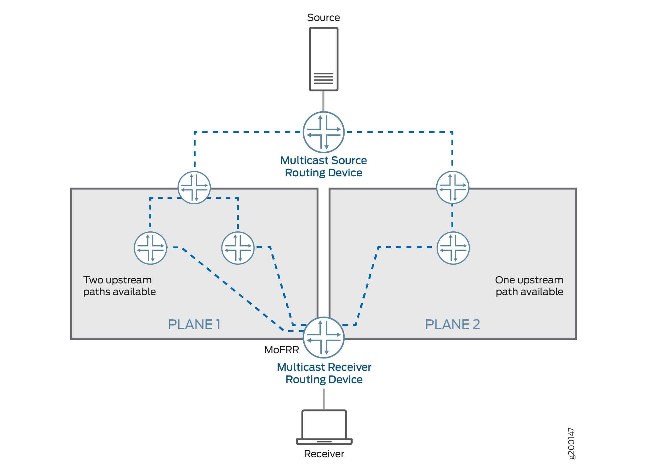
启用 MoFRR 后,出口(接收端)路由设备将为每个 (S,G) 的组播源设置两个 组播 树(主路径和备用路径)。换句话说,出口路由设备将相同的 (S,G) 加入消息传播到两个不同的上游邻接方,从而创建两个组播树。
其中一棵组播树通过平面 1,另一棵穿过平面 2,如 图 12 所示。对于每个 (S,G),出口路由设备将转发在主路径上接收的流量,并丢弃在备用路径上接收的流量。
等价多路径 (ECMP) 路径和非 ECMP 路径均支持 MoFRR。设备需要启用单播无环路备用 (LFA) 路由,以支持非 ECMP 路径上的 MoFRR。可以使用内部网关协议 (IGP) 配置中的语句启用 link-protection LFA 路由。在 OSPF 或 IS-IS 接口上启用链路保护后,设备将为遍历受保护接口的所有目标路由创建到主下一跃点的备用 LFA 路径。
Junos OS 在 IP 网络中实施 MoFRR 以实现 IP MoFRR,并在 MPLS 标签边缘路由设备 (LER) 中实施多点 LDP MoFRR。
多点 LDP MoFRR 用于 MPLS 网络的出口设备,其中数据包被转发到 IP 网络。借助多点 LDP MoFRR,设备可以建立两条指向上游 PE 路由设备的路径,以便在 LER 接收两个 MPLS 数据包流。设备接受其中一个流(主流),另一个流(备份)在 LER 处被丢弃。如果主路径出现故障,设备将改为接受备份流。支持带内信令是使用多点 LDP 的 MoFRR 的先决条件(请参阅 了解点对多点 LSP 的多点 LDP 带内信令)。
PIM 功能
Junos OS 支持 PIM 源特定组播 (SSM) 和所有源组播 (ASM) 中最短路径树 (SPT) 联接的 MoFRR。SSM 和 ASM 范围都支持 MoFRR。要为 (*,G) 连接启用 MoFRR,请在层次结构中[edit routing-options multicast stream-protection]包含mofrr-asm-starg配置语句。对于每个 G 组,MoFRR 将对 (S,G) 或 (*,G) 进行操作,但不能同时进行两者。(S,G) 始终优先于 (*,G)。
启用 MoFRR 后,PIM 路由设备会在两个上游反向路径转发 (RPF) 接口上传播加入消息,以便在两个链路上接收同一加入请求的组播流量。MoFRR 优先选择不会收敛到同一直接上游路由设备的两条路径。PIM 通过带有两个接口(用于主路径和备用路径)的上游 RPF 下一跃点安装适当的组播路由。
当主路径出现故障时,备份路径将升级为主状态,设备会相应地转发流量。如果有备用路径可用,MoFRR 将计算新的备份路径并更新或安装相应的组播路由。
您可以通过 PIM 连接负载平衡启用 MoFRR(请参阅 join-load-balance automatic 语句)。但是,在这种情况下,连接消息在链路之间的分布可能不均匀。添加新的 ECMP 链路时,将重新分配主路径上的加入消息并进行负载均衡。备份路径上的联接消息可能仍遵循相同的路径,并且可能不会均匀地重新分配。
在层次结构中使用[edit routing-options multicast]配置语句启用 stream-protection MoFRR。MoFRR 由一组过滤策略管理。
当出口 PIM 路由设备收到加入消息或 IGMP 报告时,它会检查 MoFRR 配置,并按以下步骤继续操作:
如果 MoFRR 配置不存在,PIM 会向上游的一个上游邻接方(例如, 图 12 中的平面 2)发送加入消息。
如果存在 MoFRR 配置,设备将检查策略配置。
如果策略不存在,设备将检查主路径和备份路径(上游接口),并按以下步骤继续操作:
如果存在策略,设备将检查策略是否允许为此 (S,G) 进行 MoFRR,并按以下步骤继续操作:
多点 LDP 功能
为避免 MPLS 流量重复,多点 LDP 通常只选择一个上行路径。(参见第 2.4.1.1 节。在 RFC 6388 中确定自己的“上游标签交换路由器”, 点到多点和多点到多点标签交换路径的标签分发协议扩展。)
对于使用 MoFRR 的多点 LDP,多点 LDP 设备会选择两个单独的上游对等方,并向每个上游对等方发送两个单独的标签。设备使用 RFC 6388 中描述的相同算法来选择主上游路径。设备使用相同的算法来选择备用上行路径,但将主上行标签交换路由器排除为候选。两个不同的上游对等方向出口路由设备发送两个 MPLS 流量流。设备仅选择上游邻接方路径之一作为接受 MPLS 流量的主路径。另一条路径成为备用路径,设备将丢弃该流量。当主上行路径发生故障时,设备将开始接受来自备用路径的流量。多点 LDP 设备根据内部网关协议 (IGP) 根设备下一跃点选择两个上行路径。
转发等效类 (FEC) 是一组以相同方式、在相同路径上转发并采用相同转发处理方式的 IP 数据包。通常,贴在特定数据包上的标签表示该数据包被分配到的 FEC。在 MoFRR 中,每个 FEC 的 mpls.0 表中会放置两个路由:一个路由用于主标签,另一个路由用于备份标签。
如果存在指向同一直接上游设备的并行链路,则设备会将这两个并行链路视为主链路。在任何时间点,上游设备都只会在多个并行链路中的一个上发送流量。
芽节点是一个标签交换路由器,它是一个出口标签交换路由器,但也有一个或多个直接连接的下游 LSR。对于芽节点,来自主上行路径的流量被转发到下游标签交换路由器。如果主上行路径发生故障,则来自备用上行路径的 MPLS 流量将转发到下行标签交换路由器。这意味着,下游标签交换路由器下一跃点将与出口下一跃点一起添加到两个 MPLS 路由中。
与 PIM 一样,您可以在层次结构中使用 [edit routing-options multicast] configuration 语句通过stream-protection多点 LDP 启用 MoFRR,并且它由一组过滤器策略进行管理。
如果已为 MoFRR 启用多点 LDP 点对多点 FEC,设备在选择上行路径时会考虑以下因素:
如果存在非目标 LDP 会话,则会跳过目标 LDP 会话。如果存在单个目标 LDP 会话,则会选择目标 LDP 会话,但相应的点对多点 FEC 会失去 MoFRR 功能,因为没有与目标 LDP 会话关联的接口。
属于同一上游标签交换路由器的所有接口都被视为主路径。
对于任何根节点路由更新,上游路径将根据 IGP 的最新下一跃点进行更改。如果有更好的路径可用,多点 LDP 会尝试切换到更好的路径。
数据包转发
对于 PIM 或多点 LDP,设备将在入口接口执行组播源流选择。这样可以保留交换矩阵带宽并最大限度地提高转发性能,因为:
避免跨交换矩阵发送重复流
防止多次路由查找(导致数据包丢弃)。
对于 PIM,每个 IP 组播流都包含相同的目标地址。无论数据包到达哪个接口,数据包的路由都是相同的。设备检查每个数据包到达的接口,并仅转发来自主接口的数据包。如果接口与备份流接口匹配,设备将丢弃数据包。如果接口与主流接口或备份流接口不匹配,设备会在控制平面中将数据包作为异常进行处理。
图 13 显示了此过程,以及使用 PIM 的路由器的主接口和备份接口示例。 图 14 以类似方式显示了带有 PIM 的交换机的情况。
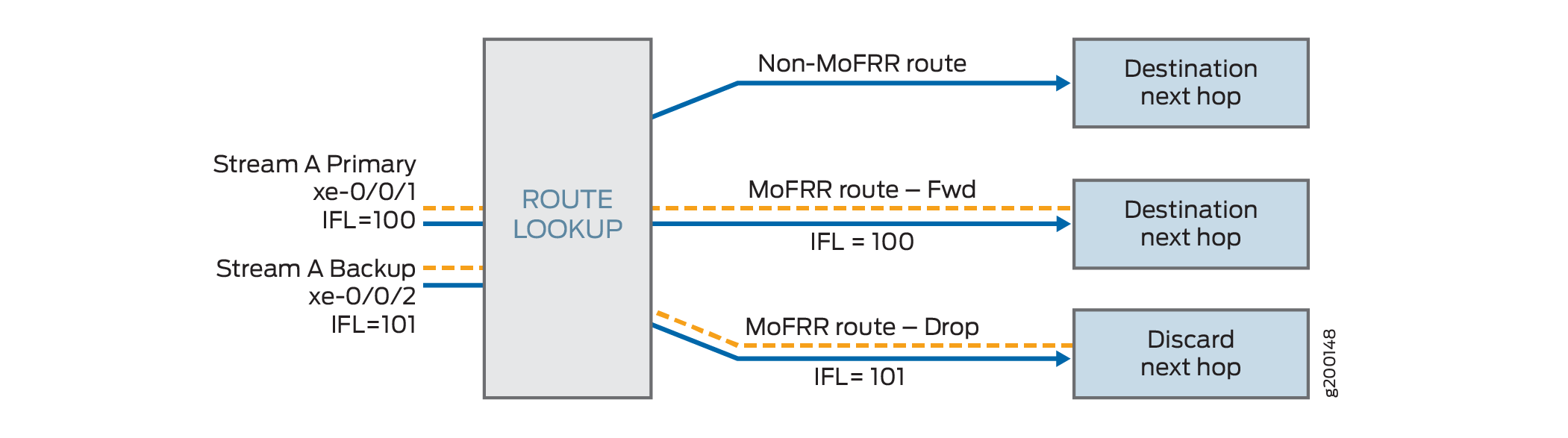
对于在路由器上使用多点 LDP 的 MoFRR,设备使用多个 MPLS 标签来控制 MoFRR 流选择。每个标签代表一个单独的路由,但每个标签引用相同的接口列表检查。设备仅转发主标签,并丢弃所有其他标签。多个接口可以接收使用同一标签的数据包。
图 15 显示了具有多点 LDP 的路由器的此过程。
限制和注意事项
关于交换和路由设备的 MoFRR 限制和注意事项
MoFRR 对路由和交换设备有以下限制和注意事项:
MoFRR 故障检测支持对启用了 MoFRR 的路由设备(而不是组播流量路径中的所有链路(端到端)进行即时链路保护。
MoFRR 支持在两个选定的不相交路径上快速重新路由,以到达源。选定的两个上游邻接方不能位于同一接口上,换句话说,即 LAN 分段上的两个上游邻接方。如果上游接口恰好是组播隧道接口,情况也是如此。
不支持检测最大端到端不相交上游路径。接收方(出口)路由设备仅确保存在不相交的上游设备(紧接的上一个跃点)。PIM 和多点 LDP 不支持显式路由对象 (ERO) 的等效功能。因此,不相交的上游路径检测仅限于对紧接着的上一个跃点设备的控制。由于此限制,到选择为主和备份的上一个跃点的上游设备的路径可能会被共享。
在以下情况下,您可能会看到一些流量丢失:
更好的上行路径可在出口设备上使用。
当有活动流量流流动时,MoFRR 将在出口设备上启用或禁用。
不支持备份路径的联接消息的 PIM 联接负载平衡。
对于组播组 G,不允许 (S,G) 和 (*,G) 加入消息进行 MoFRR。(S,G) 加入消息优先于 (*,G)。
使用两个不同组播组的组播流量流不支持 MoFRR。每个 (S,G) 组合都被视为唯一的组播流量流。
MoFRR 不支持双向 PIM 范围。
MoFRR 不支持 PIM 密集模式。
PIM 不维护备用流量流的组播统计信息,因此在命令的
show操作输出中不可用。不支持速率监控。
使用 PIM 进行交换设备的 MoFRR 限制
使用 PIM 的 MoFRR 对交换设备有以下限制:
当上游接口是集成路由和桥接 (IRB) 接口时,不支持 MoFRR,这会影响其他组播功能,如互联网组管理协议第 3 版 (IGMPv3) 侦听。
转发组播流量时进行的数据包复制和组播查找会导致数据包多次通过 PFE 再循环。因此,命令显示
show pfe statistics traffic的组播数据包计数值在输出字段(如Input packets和Output packets)中显示的数字可能高于预期的数字。在 MoFRR 场景中,您可能会更频繁地注意到此行为,因为重复的主流和备份流通常会增加流量。
使用多点 LDP 的路由设备的 MoFRR 限制和注意事项
当与多点 LDP 配合使用时,MoFRR 对路由器有以下限制和注意事项:
MoFRR 不适用于在 RSVP 隧道上接收的多点 LDP 流量,因为 RSVP 隧道未与任何接口关联。
不支持混合上游 MoFRR。这是指 PIM 多点 LDP 带内信令,其中一条上行路径通过多点 LDP,第二条上行路径通过 PIM。
不支持将多点 LDP 标签用作内部标签。
如果可通过多个入口(源端)提供商边缘 (PE) 路由设备访问源,则不支持多点 LDP MoFRR。
目标 LDP 上游会话不会被选为 MoFRR 的上游设备。
不支持备份路径上的多点 LDP 链路保护,因为不支持 MoFRR 内部标签。
配置仅限组播的快速重新路由
您可以配置仅组播快速重新路由 (MoFRR),以便在发生链路故障时最大程度地减少网络中的数据包丢失。
当快速重新路由应用于单播流时,上游路由器会预先建立 MPLS 标签交换路径 (LSP) 或预先计算 IP 无环路备用 (LFA) 快速重新路由备份路径,以处理下行路径中某个分段的故障。
在组播路由中,流量分布图通常源自接收方。这与单播路由不同,路由通常建立从源到接收器的路径。能够建立组播分布图的协议有 PIM(用于 IP)、多点 LDP(用于 MPLS)和 RSVP-流量工程(用于 MPLS)。其中,PIM 和多点 LDP 接收器启动分布图设置,因此:
在 QFX 系列上,PIM 域支持 MoFRR。
在 MX 系列和 SRX 系列上,PIM 和多点 LDP 域支持 MoFRR。
除非另有说明,否则在支持此功能的所有设备上为 PIM 启用 MoFRR 的配置步骤相同。还指出了不适用于多点 LDP MoFRR 的配置步骤。
(仅适用于 MX 系列路由器)带有 MPC 线卡的 MX 系列路由器支持 MoFRR。作为先决条件,路由器中的所有线卡都必须是 MPC。
要在路由器或交换机上配置 MoFRR:
示例:在多点 LDP 域中配置仅组播快速重新路由
此示例说明如何配置仅组播快速重新路由 (MoFRR),以便在发生链路故障时最大程度地减少网络中的数据包丢失。
多点 LDP MoFRR 用于 MPLS 网络的出口节点,数据包在此转发至 IP 网络。如果采用多点 LDP MoFRR,将建立通向上游提供商边缘 (PE) 路由器的两条路径,以便在标签边缘路由器 (LER) 上接收两个 MPLS 数据包流。接受其中一个流(主流),另一个流(备份)在 LER 上被丢弃。如果主路径失败,则接受备份流。
要求
配置此示例之前,不需要除设备初始化之外的特殊配置。
在多点 LDP 域中,只有出口 PE 路由器需要启用 MoFRR,才能使 MoFRR 正常工作。其他路由器不需要支持 MoFRR。
带有 MPC 线卡的 MX 系列平台支持 MoFRR。作为先决条件,必须将路由器设置为 network-services enhanced-ip 模式,并且平台中的所有线卡都必须是 MPC。
此示例要求出口 PE 路由器上安装 Junos OS 14.1 或更高版本。
概述
在此示例中,设备 R3 是出口边缘路由器。MoFRR 仅在此设备上启用。
OSPF 用于连接,但可以使用任何内部网关协议 (IGP) 或静态路由。
出于测试目的,路由器用于模拟源和接收方。设备 R4 和设备 R8 配置为使用 set protocols igmp interface interface-name static group group 命令静态加入所需组。如果实际组播接收器主机不可用(如本例所示),此静态 IGMP 配置很有用。在接收器上,为了使其侦听组播组地址,此示例使用 set protocols sap listen group。
MoFRR 配置包括一个策略选项,此示例中未显示,但将单独解释。该选项配置如下:
stream-protection {
    policy policy-name;
}
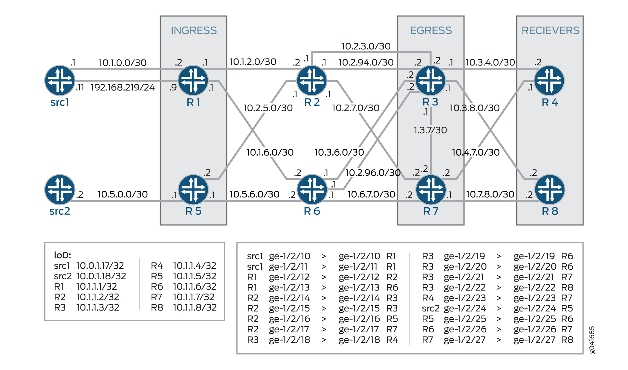
CLI 快速配置
CLI 快速配置
要快速配置此示例,请复制以下命令,将其粘贴到文本文件中,删除所有换行符,更改详细信息,以便与网络配置匹配,然后将命令复制并粘贴到层次结构级别的 [edit] CLI 中。
设备 src1
set interfaces ge-1/2/10 unit 0 description src1-to-R1
set interfaces ge-1/2/10 unit 0 family inet address 10.5.0.1/30
set interfaces ge-1/2/11 unit 0 description src1-to-R1
set interfaces ge-1/2/11 unit 0 family inet address 192.168.219.11/24
set interfaces lo0 unit 0 family inet address 10.0.1.17/32
set protocols ospf area 0.0.0.0 interface all
set protocols ospf area 0.0.0.0 interface lo0.0 passive
设备 src2
set interfaces ge-1/2/24 unit 0 description src2-to-R5
set interfaces ge-1/2/24 unit 0 family inet address 10.5.0.2/30
set interfaces lo0 unit 0 family inet address 10.0.1.18/32
set protocols rsvp interface all
set protocols ospf area 0.0.0.0 interface all
set protocols ospf area 0.0.0.0 interface lo0.0 passive
设备 R1
set interfaces ge-1/2/12 unit 0 description R1-to-R2
set interfaces ge-1/2/12 unit 0 family inet address 10.1.2.1/30
set interfaces ge-1/2/12 unit 0 family mpls
set interfaces ge-1/2/13 unit 0 description R1-to-R6
set interfaces ge-1/2/13 unit 0 family inet address 10.1.6.1/30
set interfaces ge-1/2/13 unit 0 family mpls
set interfaces ge-1/2/10 unit 0 description R1-to-src1
set interfaces ge-1/2/10 unit 0 family inet address 10.1.0.2/30
set interfaces ge-1/2/11 unit 0 description R1-to-src1
set interfaces ge-1/2/11 unit 0 family inet address 192.168.219.9/30
set interfaces lo0 unit 0 family inet address 10.1.1.1/32
set protocols rsvp interface all
set protocols mpls interface all
set protocols bgp group ibgp local-address 10.1.1.1
set protocols bgp group ibgp export static-route-tobgp
set protocols bgp group ibgp peer-as 65010
set protocols bgp group ibgp neighbor 10.1.1.3
set protocols bgp group ibgp neighbor 10.1.1.7
set protocols ospf traffic-engineering
set protocols ospf area 0.0.0.0 interface all
set protocols ospf area 0.0.0.0 interface lo0.0 passive
set protocols ldp interface ge-1/2/12.0
set protocols ldp interface ge-1/2/13.0
set protocols ldp interface lo0.0
set protocols ldp p2mp
set protocols pim mldp-inband-signalling policy mldppim-ex
set protocols pim rp static address 10.1.1.5
set protocols pim interface lo0.0
set protocols pim interface ge-1/2/10.0
set protocols pim interface ge-1/2/11.0
set policy-options policy-statement mldppim-ex term B from source-address-filter 192.168.0.0/24 orlonger
set policy-options policy-statement mldppim-ex term B from source-address-filter 192.168.219.11/32 orlonger
set policy-options policy-statement mldppim-ex term B then p2mp-lsp-root address 10.1.1.2
set policy-options policy-statement mldppim-ex term B then accept
set policy-options policy-statement mldppim-ex term A from source-address-filter 10.1.1.7/32 orlonger
set policy-options policy-statement mldppim-ex term A from source-address-filter 10.1.0.0/30 orlonger
set policy-options policy-statement mldppim-ex term A then accept
set policy-options policy-statement static-route-tobgp term static from protocol static
set policy-options policy-statement static-route-tobgp term static from protocol direct
set policy-options policy-statement static-route-tobgp term static then accept
set routing-options autonomous-system 65010
设备 R2
set interfaces ge-1/2/12 unit 0 description R2-to-R1
set interfaces ge-1/2/12 unit 0 family inet address 10.1.2.2/30
set interfaces ge-1/2/12 unit 0 family mpls
set interfaces ge-1/2/14 unit 0 description R2-to-R3
set interfaces ge-1/2/14 unit 0 family inet address 10.2.3.1/30
set interfaces ge-1/2/14 unit 0 family mpls
set interfaces ge-1/2/16 unit 0 description R2-to-R5
set interfaces ge-1/2/16 unit 0 family inet address 10.2.5.1/30
set interfaces ge-1/2/16 unit 0 family mpls
set interfaces ge-1/2/17 unit 0 description R2-to-R7
set interfaces ge-1/2/17 unit 0 family inet address 10.2.7.1/30
set interfaces ge-1/2/17 unit 0 family mpls
set interfaces ge-1/2/15 unit 0 description R2-to-R3
set interfaces ge-1/2/15 unit 0 family inet address 10.2.94.1/30
set interfaces ge-1/2/15 unit 0 family mpls
set interfaces lo0 unit 0 family inet address 10.1.1.2/32
set interfaces lo0 unit 0 family mpls
set protocols rsvp interface all
set protocols mpls interface all
set protocols ospf traffic-engineering
set protocols ospf area 0.0.0.0 interface all
set protocols ospf area 0.0.0.0 interface lo0.0 passive
set protocols ldp interface all
set protocols ldp p2mp
set policy-options policy-statement mldppim-ex term B from source-address-filter 192.168.0.0/24 orlonger
set policy-options policy-statement mldppim-ex term B from source-address-filter 192.168.219.11/32 orlonger
set policy-options policy-statement mldppim-ex term B then p2mp-lsp-root address 10.1.1.2
set policy-options policy-statement mldppim-ex term B then accept
set routing-options autonomous-system 65010
设备 R3
set chassis network-services enhanced-ip
set interfaces ge-1/2/14 unit 0 description R3-to-R2
set interfaces ge-1/2/14 unit 0 family inet address 10.2.3.2/30
set interfaces ge-1/2/14 unit 0 family mpls
set interfaces ge-1/2/18 unit 0 description R3-to-R4
set interfaces ge-1/2/18 unit 0 family inet address 10.3.4.1/30
set interfaces ge-1/2/18 unit 0 family mpls
set interfaces ge-1/2/19 unit 0 description R3-to-R6
set interfaces ge-1/2/19 unit 0 family inet address 10.3.6.2/30
set interfaces ge-1/2/19 unit 0 family mpls
set interfaces ge-1/2/21 unit 0 description R3-to-R7
set interfaces ge-1/2/21 unit 0 family inet address 10.3.7.1/30
set interfaces ge-1/2/21 unit 0 family mpls
set interfaces ge-1/2/22 unit 0 description R3-to-R8
set interfaces ge-1/2/22 unit 0 family inet address 10.3.8.1/30
set interfaces ge-1/2/22 unit 0 family mpls
set interfaces ge-1/2/15 unit 0 description R3-to-R2
set interfaces ge-1/2/15 unit 0 family inet address 10.2.94.2/30
set interfaces ge-1/2/15 unit 0 family mpls
set interfaces ge-1/2/20 unit 0 description R3-to-R6
set interfaces ge-1/2/20 unit 0 family inet address 10.2.96.2/30
set interfaces ge-1/2/20 unit 0 family mpls
set interfaces lo0 unit 0 family inet address 10.1.1.3/32 primary
set routing-options autonomous-system 65010
set routing-options multicast stream-protection
set protocols rsvp interface all
set protocols mpls interface all
set protocols bgp group ibgp local-address 10.1.1.3
set protocols bgp group ibgp peer-as 10
set protocols bgp group ibgp neighbor 10.1.1.1
set protocols bgp group ibgp neighbor 10.1.1.5
set protocols ospf traffic-engineering
set protocols ospf area 0.0.0.0 interface all
set protocols ospf area 0.0.0.0 interface fxp0.0 disable
set protocols ospf area 0.0.0.0 interface lo0.0 passive
set protocols ldp interface all
set protocols ldp p2mp
set protocols pim mldp-inband-signalling policy mldppim-ex
set protocols pim interface lo0.0
set protocols pim interface ge-1/2/18.0
set protocols pim interface ge-1/2/22.0
set policy-options policy-statement mldppim-ex term B from source-address-filter 192.168.0.0/24 orlonger
set policy-options policy-statement mldppim-ex term B from source-address-filter 192.168.219.11/32 orlonger
set policy-options policy-statement mldppim-ex term B then accept
set policy-options policy-statement mldppim-ex term A from source-address-filter 10.1.0.1/30 orlonger
set policy-options policy-statement mldppim-ex term A then accept
set policy-options policy-statement static-route-tobgp term static from protocol static
set policy-options policy-statement static-route-tobgp term static from protocol direct
set policy-options policy-statement static-route-tobgp term static then accept
设备 R4
set interfaces ge-1/2/18 unit 0 description R4-to-R3
set interfaces ge-1/2/18 unit 0 family inet address 10.3.4.2/30
set interfaces ge-1/2/18 unit 0 family mpls
set interfaces ge-1/2/23 unit 0 description R4-to-R7
set interfaces ge-1/2/23 unit 0 family inet address 10.4.7.1/30
set interfaces lo0 unit 0 family inet address 10.1.1.4/32
set protocols igmp interface ge-1/2/18.0 version 3
set protocols igmp interface ge-1/2/18.0 static group 232.1.1.1 group-count 2
set protocols igmp interface ge-1/2/18.0 static group 232.1.1.1 source 192.168.219.11
set protocols igmp interface ge-1/2/18.0 static group 232.2.2.2 source 10.2.7.7
set protocols sap listen 232.1.1.1
set protocols sap listen 232.2.2.2
set protocols rsvp interface all
set protocols mpls interface all
set protocols ospf traffic-engineering
set protocols ospf area 0.0.0.0 interface all
set protocols ospf area 0.0.0.0 interface lo0.0 passive
set protocols pim mldp-inband-signalling policy mldppim-ex
set protocols pim interface ge-1/2/23.0
set protocols pim interface ge-1/2/18.0
set protocols pim interface lo0.0
set policy-options policy-statement static-route-tobgp term static from protocol static
set policy-options policy-statement static-route-tobgp term static from protocol direct
set policy-options policy-statement static-route-tobgp term static then accept
set policy-options policy-statement mldppim-ex term B from source-address-filter 192.168.0.0/24 orlonger
set policy-options policy-statement mldppim-ex term B from source-address-filter 192.168.219.11/32 orlonger
set policy-options policy-statement mldppim-ex term B then p2mp-lsp-root address 10.1.1.2
set policy-options policy-statement mldppim-ex term B then accept
set routing-options autonomous-system 65010
设备 R5
set interfaces ge-1/2/24 unit 0 description R5-to-src2
set interfaces ge-1/2/24 unit 0 family inet address 10.5.0.1/30
set interfaces ge-1/2/16 unit 0 description R5-to-R2
set interfaces ge-1/2/16 unit 0 family inet address 10.2.5.2/30
set interfaces ge-1/2/16 unit 0 family mpls
set interfaces ge-1/2/25 unit 0 description R5-to-R6
set interfaces ge-1/2/25 unit 0 family inet address 10.5.6.1/30
set interfaces ge-1/2/25 unit 0 family mpls
set interfaces lo0 unit 0 family inet address 10.1.1.5/32
set protocols rsvp interface all
set protocols mpls interface all
set protocols bgp group ibgp local-address 10.1.1.5
set protocols bgp group ibgp export static-route-tobgp
set protocols bgp group ibgp peer-as 65010
set protocols bgp group ibgp neighbor 10.1.1.7
set protocols bgp group ibgp neighbor 10.1.1.3
set protocols ospf traffic-engineering
set protocols ospf area 0.0.0.0 interface all
set protocols ospf area 0.0.0.0 interface lo0.0 passive
set protocols ldp interface ge-1/2/16.0
set protocols ldp interface ge-1/2/25.0
set protocols ldp p2mp
set protocols pim interface lo0.0
set protocols pim interface ge-1/2/24.0
set policy-options policy-statement static-route-tobgp term static from protocol static
set policy-options policy-statement static-route-tobgp term static from protocol direct
set policy-options policy-statement static-route-tobgp term static then accept
set routing-options autonomous-system 65010
设备 R6
set interfaces ge-1/2/13 unit 0 description R6-to-R1
set interfaces ge-1/2/13 unit 0 family inet address 10.1.6.2/30
set interfaces ge-1/2/13 unit 0 family mpls
set interfaces ge-1/2/19 unit 0 description R6-to-R3
set interfaces ge-1/2/19 unit 0 family inet address 10.3.6.1/30
set interfaces ge-1/2/19 unit 0 family mpls
set interfaces ge-1/2/25 unit 0 description R6-to-R5
set interfaces ge-1/2/25 unit 0 family inet address 10.5.6.2/30
set interfaces ge-1/2/25 unit 0 family mpls
set interfaces ge-1/2/26 unit 0 description R6-to-R7
set interfaces ge-1/2/26 unit 0 family inet address 10.6.7.1/30
set interfaces ge-1/2/26 unit 0 family mpls
set interfaces ge-1/2/20 unit 0 description R6-to-R3
set interfaces ge-1/2/20 unit 0 family inet address 10.2.96.1/30
set interfaces ge-1/2/20 unit 0 family mpls
set interfaces lo0 unit 0 family inet address 10.1.1.6/30
set protocols rsvp interface all
set protocols mpls interface all
set protocols ospf traffic-engineering
set protocols ospf area 0.0.0.0 interface all
set protocols ospf area 0.0.0.0 interface lo0.0 passive
set protocols ldp interface all
set protocols ldp p2mp
设备 R7
set interfaces ge-1/2/17 unit 0 description R7-to-R2
set interfaces ge-1/2/17 unit 0 family inet address 10.2.7.2/30
set interfaces ge-1/2/17 unit 0 family mpls
set interfaces ge-1/2/21 unit 0 description R7-to-R3
set interfaces ge-1/2/21 unit 0 family inet address 10.3.7.2/30
set interfaces ge-1/2/21 unit 0 family mpls
set interfaces ge-1/2/23 unit 0 description R7-to-R4
set interfaces ge-1/2/23 unit 0 family inet address 10.4.7.2/30
set interfaces ge-1/2/23 unit 0 family mpls
set interfaces ge-1/2/26 unit 0 description R7-to-R6
set interfaces ge-1/2/26 unit 0 family inet address 10.6.7.2/30
set interfaces ge-1/2/26 unit 0 family mpls
set interfaces ge-1/2/27 unit 0 description R7-to-R8
set interfaces ge-1/2/27 unit 0 family inet address 10.7.8.1/30
set interfaces ge-1/2/27 unit 0 family mpls
set interfaces lo0 unit 0 family inet address 10.1.1.7/32
set protocols rsvp interface all
set protocols mpls interface all
set protocols bgp group ibgp local-address 10.1.1.7
set protocols bgp group ibgp export static-route-tobgp
set protocols bgp group ibgp peer-as 65010
set protocols bgp group ibgp neighbor 10.1.1.5
set protocols bgp group ibgp neighbor 10.1.1.1
set protocols ospf traffic-engineering
set protocols ospf area 0.0.0.0 interface all
set protocols ospf area 0.0.0.0 interface lo0.0 passive
set protocols ldp interface ge-1/2/17.0
set protocols ldp interface ge-1/2/21.0
set protocols ldp interface ge-1/2/26.0
set protocols ldp p2mp
set protocols pim mldp-inband-signalling policy mldppim-ex
set protocols pim interface lo0.0
set protocols pim interface ge-1/2/27.0
set policy-options policy-statement mldppim-ex term B from source-address-filter 192.168.0.0/24 orlonger
set policy-options policy-statement mldppim-ex term B from source-address-filter 192.168.219.11/32 orlonger
set policy-options policy-statement mldppim-ex term B then accept
set policy-options policy-statement mldppim-ex term A from source-address-filter 10.1.0.1/30 orlonger
set policy-options policy-statement mldppim-ex term A then accept
set policy-options policy-statement static-route-tobgp term static from protocol static
set policy-options policy-statement static-route-tobgp term static from protocol direct
set policy-options policy-statement static-route-tobgp term static then accept
set routing-options autonomous-system 65010
set routing-options multicast stream-protection policy mldppim-ex
设备 R8
set interfaces ge-1/2/22 unit 0 description R8-to-R3
set interfaces ge-1/2/22 unit 0 family inet address 10.3.8.2/30
set interfaces ge-1/2/22 unit 0 family mpls
set interfaces ge-1/2/27 unit 0 description R8-to-R7
set interfaces ge-1/2/27 unit 0 family inet address 10.7.8.2/30
set interfaces ge-1/2/27 unit 0 family mpls
set interfaces lo0 unit 0 family inet address 10.1.1.8/32
set protocols igmp interface ge-1/2/22.0 version 3
set protocols igmp interface ge-1/2/22.0 static group 232.1.1.1 group-count 2
set protocols igmp interface ge-1/2/22.0 static group 232.1.1.1 source 192.168.219.11
set protocols igmp interface ge-1/2/22.0 static group 232.2.2.2 source 10.2.7.7
set protocols sap listen 232.1.1.1
set protocols sap listen 232.2.2.2
set protocols rsvp interface all
set protocols ospf traffic-engineering
set protocols ospf area 0.0.0.0 interface all
set protocols ospf area 0.0.0.0 interface lo0.0 passive
set protocols pim mldp-inband-signalling policy mldppim-ex
set protocols pim interface ge-1/2/27.0
set protocols pim interface ge-1/2/22.0
set protocols pim interface lo0.0
set policy-options policy-statement static-route-tobgp term static from protocol static
set policy-options policy-statement static-route-tobgp term static from protocol direct
set policy-options policy-statement static-route-tobgp term static then accept
set policy-options policy-statement mldppim-ex term B from source-address-filter 192.168.0.0/24 orlonger
set policy-options policy-statement mldppim-ex term B from source-address-filter 192.168.219.11/32 orlonger
set policy-options policy-statement mldppim-ex term B then p2mp-lsp-root address 10.1.1.2
set policy-options policy-statement mldppim-ex term B then accept
set routing-options autonomous-system 65010
配置
过程
分步程序
下面的示例要求您在各个配置层级中进行导航。有关导航CLI的信息,请参阅《Junos OS CLI 用户指南》中的在配置模式下使用CLI编辑器。
要配置设备 R3:
启用增强型 IP 模式。
[edit chassis]
user@R3# set network-services enhanced-ip
配置设备接口。
[edit interfaces]
user@R3# set ge-1/2/14 unit 0 description R3-to-R2
user@R3# set ge-1/2/14 unit 0 family inet address 10.2.3.2/30
user@R3# set ge-1/2/14 unit 0 family mpls
user@R3# set ge-1/2/18 unit 0 description R3-to-R4
user@R3# set ge-1/2/18 unit 0 family inet address 10.3.4.1/30
user@R3# set ge-1/2/18 unit 0 family mpls
user@R3# set ge-1/2/19 unit 0 description R3-to-R6
user@R3# set ge-1/2/19 unit 0 family inet address 10.3.6.2/30
user@R3# set ge-1/2/19 unit 0 family mpls
user@R3# set ge-1/2/21 unit 0 description R3-to-R7
user@R3# set ge-1/2/21 unit 0 family inet address 10.3.7.1/30
user@R3# set ge-1/2/21 unit 0 family mpls
user@R3# set ge-1/2/22 unit 0 description R3-to-R8
user@R3# set ge-1/2/22 unit 0 family inet address 10.3.8.1/30
user@R3# set ge-1/2/22 unit 0 family mpls
user@R3# set ge-1/2/15 unit 0 description R3-to-R2
user@R3# set ge-1/2/15 unit 0 family inet address 10.2.94.2/30
user@R3# set ge-1/2/15 unit 0 family mpls
user@R3# set ge-1/2/20 unit 0 description R3-to-R6
user@R3# set ge-1/2/20 unit 0 family inet address 10.2.96.2/30
user@R3# set ge-1/2/20 unit 0 family mpls
user@R3# set lo0 unit 0 family inet address 10.1.1.3/32 primary
配置自治系统 (AS) 编号。
user@R3# set routing-options autonomous-system 6510
配置路由策略。
[edit policy-options policy-statement mldppim-ex]
user@R3# set term B from source-address-filter 192.168.0.0/24 orlonger
user@R3# set term B from source-address-filter 192.168.219.11/32 orlonger
user@R3# set term B then accept
user@R3# set term A from source-address-filter 10.1.0.1/30 orlonger
user@R3# set term A then accept
[edit policy-options policy-statement static-route-tobgp]
user@R3# set  term static from protocol static
user@R3# set  term static from protocol direct
user@R3# set term static then accept
配置 PIM。
[edit protocols pim]
user@R3# set mldp-inband-signalling policy mldppim-ex
user@R3# set interface lo0.0
user@R3# set interface ge-1/2/18.0
user@R3# set interface ge-1/2/22.0
配置 LDP。
[edit protocols ldp]
user@R3# set interface all
user@R3# set p2mp
配置 IGP 或静态路由。
[edit protocols ospf]
user@R3# set traffic-engineering
user@R3# set area 0.0.0.0 interface all
user@R3# set area 0.0.0.0 interface fxp0.0 disable
user@R3# set area 0.0.0.0 interface lo0.0 passive
配置内部 BGP。
[edit protocols bgp group ibgp]
user@R3# set local-address 10.1.1.3
user@R3# set peer-as 65010
user@R3# set neighbor 10.1.1.1
user@R3# set neighbor 10.1.1.5
配置 MPLS 和 RSVP(可选)。
[edit protocols mpls]
user@R3# set interface all
[edit protocols rsvp]
user@R3# set interface all
启用 MoFRR。
[edit routing-options multicast]
user@R3# set stream-protection
结果
在配置模式下,输入 show chassis、 show interfaces、 show policy-optionsshow protocols和show routing-options命令以确认您的配置。如果输出未显示预期的配置,请重复此示例中的说明以更正配置。
user@R3# show chassis
network-services enhanced-ip;
user@R3# show interfaces
ge-1/2/14 {
    unit 0 {
        description R3-to-R2;
        family inet {
            address 10.2.3.2/30;
        }
        family mpls;
    }
}
ge-1/2/18 {
    unit 0 {
        description R3-to-R4;
        family inet {
            address 10.3.4.1/30;
        }
        family mpls;
    }
}
ge-1/2/19 {
    unit 0 {
        description R3-to-R6;
        family inet {
            address 10.3.6.2/30;
        }
        family mpls;
    }
}
ge-1/2/21 {
    unit 0 {
        description R3-to-R7;
        family inet {
            address 10.3.7.1/30;
        }
        family mpls;
    }
}
ge-1/2/22 {
    unit 0 {
        description R3-to-R8;
        family inet {
            address 10.3.8.1/30;
        }
        family mpls;
    }
}
ge-1/2/15 {
    unit 0 {
        description R3-to-R2;
        family inet {
            address 10.2.94.2/30;
        }
        family mpls;
    }
}
ge-1/2/20 {
    unit 0 {
        description R3-to-R6;
        family inet {
            address 10.2.96.2/30;
        }
        family mpls;
    }
}
lo0 {
    unit 0 {
        family inet {
            address 192.168.15.1/32;
            address 10.1.1.3/32 {
                primary;
            }
        }
    }
}
user@R3# show protocols
rsvp {
    interface all;
}
mpls {
    interface all;
}
bgp {
    group ibgp {
        local-address 10.1.1.3;
        peer-as 65010;
        neighbor 10.1.1.1;
        neighbor 10.1.1.5;
    }
}
ospf {
    traffic-engineering;
    area 0.0.0.0 {
        interface all;
        interface fxp0.0 {
            disable;
        }
        interface lo0.0 {
            passive;
        }
    }
}
ldp {
    interface all;
    p2mp;
}
pim {
    mldp-inband-signalling {
        policy mldppim-ex;
    }
    interface lo0.0;
    interface ge-1/2/18.0;
    interface ge-1/2/22.0;
}
user@R3# show policy-options
policy-statement mldppim-ex {
    term B {
        from {
            source-address-filter 192.168.0.0/24 orlonger;
            source-address-filter 192.168.219.11/32 orlonger;
        }
        then accept;
    }
    term A {
        from {
            source-address-filter 10.1.0.1/30 orlonger;
        }
        then accept;
    }
}
policy-statement static-route-tobgp {
    term static {
        from protocol [ static direct ];
        then accept;
    }
}
user@R3# show routing-options
autonomous-system 65010;
multicast {
    stream-protection;
}
如果完成设备配置,请从配置模式进入。commit
验证
确认配置工作正常。
检查 LDP 点对多点转发同等类
目的
确保启用 MoFRR,并确定正在使用哪些标签。
行动
user@R3> show ldp p2mp fec

LDP P2MP FECs:
 P2MP root-addr 10.1.1.1, grp: 232.1.1.1, src: 192.168.219.11
  MoFRR enabled
  Fec type: Egress (Active)
  Label: 301568
 P2MP root-addr 10.1.1.1, grp: 232.1.1.2, src: 192.168.219.11
  MoFRR enabled
  Fec type: Egress (Active)
  Label: 301600
意义
输出显示 MoFRR 已启用,并且标签 301568 和 301600 用于两个多点 LDP 点对多点 LSP。
检查标签信息
目的
确保出口设备有两个用于加入组播组的上游接口。
行动
user@R3> show route label 301568 detail

mpls.0: 18 destinations, 18 routes (18 active, 0 holddown, 0 hidden)
301568 (1 entry, 1 announced)
        *LDP    Preference: 9
                Next hop type: Flood
                Address: 0x2735208
                Next-hop reference count: 3
                Next hop type: Router, Next hop index: 1397
                Address: 0x2735d2c
                Next-hop reference count: 3
                Next hop: 10.3.8.2 via ge-1/2/22.0
                Label operation: Pop
                Load balance label:  None;
                Next hop type: Router, Next hop index: 1395
                Address: 0x2736290
                Next-hop reference count: 3
                Next hop: 10.3.4.2 via ge-1/2/18.0
                Label operation: Pop
                Load balance label:  None;
                State: <Active Int AckRequest MulticastRPF>
                Local AS:    65010
                Age: 54:05      Metric: 1
                Validation State: unverified
                Task: LDP
                Announcement bits (1): 0-KRT
                AS path: I
                FECs bound to route: P2MP root-addr 10.1.1.1, grp: 232.1.1.1, src: 192.168.219.11
                Primary Upstream : 10.1.1.3:0--10.1.1.2:0
                   RPF Nexthops  :
                        ge-1/2/15.0, 10.2.94.1, Label: 301568, weight: 0x1
                        ge-1/2/14.0, 10.2.3.1, Label: 301568, weight: 0x1
                Backup Upstream : 10.1.1.3:0--10.1.1.6:0
                   RPF Nexthops :
                        ge-1/2/20.0, 10.2.96.1, Label: 301584, weight: 0xfffe
                        ge-1/2/19.0, 10.3.6.1, Label: 301584, weight: 0xfffe
user@R3> show route label 301600 detail

mpls.0: 18 destinations, 18 routes (18 active, 0 holddown, 0 hidden)
301600 (1 entry, 1 announced)
        *LDP    Preference: 9
                Next hop type: Flood
                Address: 0x27356b4
                Next-hop reference count: 3
                Next hop type: Router, Next hop index: 1520
                Address: 0x27350f4
                Next-hop reference count: 3
                Next hop: 10.3.8.2 via ge-1/2/22.0
                Label operation: Pop
                Load balance label:  None;
                Next hop type: Router, Next hop index: 1481
                Address: 0x273645c
                Next-hop reference count: 3
                Next hop: 10.3.4.2 via ge-1/2/18.0
                Label operation: Pop
                Load balance label:  None;
                State: <Active Int AckRequest MulticastRPF>
                Local AS:    65010
                Age: 54:25      Metric: 1
                Validation State: unverified
                Task: LDP
                Announcement bits (1): 0-KRT
                AS path: I
                FECs bound to route: P2MP root-addr 10.1.1.1, grp: 232.1.1.2, src: 192.168.219.11
                Primary Upstream : 10.1.1.3:0--10.1.1.6:0
                   RPF Nexthops  :
                        ge-1/2/20.0, 10.2.96.1, Label: 301600, weight: 0x1
                        ge-1/2/19.0, 10.3.6.1, Label: 301600, weight: 0x1
                Backup Upstream : 10.1.1.3:0--1.1.1.2:0
                   RPF Nexthops :
                        ge-1/2/15.0, 10.2.94.1, Label: 301616, weight: 0xfffe
                        ge-1/2/14.0, 10.2.3.1, Label: 301616, weight: 0xfffe
意义
输出显示主上行路径和备用上行路径。它还显示 RPF 下一跃点。
检查组播路由
目的
检查 IP 组播转发表,确保存在包含主接口和备用接口的上游 RPF 接口列表。
行动
user@R3> show ldp p2mp path
P2MP path type: Transit/Egress
  Output Session (label): 10.1.1.2:0 (301568) (Primary)
  Egress Nexthops: Interface ge-1/2/18.0
                   Interface ge-1/2/22.0
  RPF Nexthops:    Interface ge-1/2/15.0, 10.2.94.1, 301568, 1
                   Interface ge-1/2/20.0, 10.2.96.1, 301584, 65534
                   Interface ge-1/2/14.0, 10.2.3.1, 301568, 1
                   Interface ge-1/2/19.0, 10.3.6.1, 301584, 65534
  Attached FECs:  P2MP root-addr 10.1.1.1, grp: 232.1.1.1, src: 192.168.219.11 (Active)
P2MP path type: Transit/Egress
  Output Session (label): 10.1.1.6:0 (301584) (Backup)
  Egress Nexthops: Interface ge-1/2/18.0
                   Interface ge-1/2/22.0
  RPF Nexthops:    Interface ge-1/2/15.0, 10.2.94.1, 301568, 1
                   Interface ge-1/2/20.0, 10.2.96.1, 301584, 65534
                   Interface ge-1/2/14.0, 10.2.3.1, 301568, 1
                   Interface ge-1/2/19.0, 10.3.6.1, 301584, 65534
  Attached FECs:  P2MP root-addr 10.1.1.1, grp: 232.1.1.1, src: 192.168.219.11 (Active)
P2MP path type: Transit/Egress
  Output Session (label): 10.1.1.6:0 (301600) (Primary)
  Egress Nexthops: Interface ge-1/2/18.0
                   Interface ge-1/2/22.0
  RPF Nexthops:    Interface ge-1/2/15.0, 10.2.94.1, 301616, 65534
                   Interface ge-1/2/20.0, 10.2.96.1, 301600, 1
                   Interface ge-1/2/14.0, 10.2.3.1, 301616, 65534
                   Interface ge-1/2/19.0, 10.3.6.1, 301600, 1
  Attached FECs:  P2MP root-addr 10.1.1.1, grp: 232.1.1.2, src: 192.168.219.11 (Active)
P2MP path type: Transit/Egress
  Output Session (label): 10.1.1.2:0 (301616) (Backup)
  Egress Nexthops: Interface ge-1/2/18.0
                   Interface ge-1/2/22.0
  RPF Nexthops:    Interface ge-1/2/15.0, 10.2.94.1, 301616, 65534
                   Interface ge-1/2/20.0, 10.2.96.1, 301600, 1
                   Interface ge-1/2/14.0, 10.2.3.1, 301616, 65534
                   Interface ge-1/2/19.0, 10.3.6.1, 301600, 1
  Attached FECs:  P2MP root-addr 10.1.1.1, grp: 232.1.1.2, src: 192.168.219.11 (Active)
意义
输出显示主会话和备份会话以及 RPF 下一跃点。
检查 LDP 点对多点流量统计信息
目的
确保同时列出了主统计信息和备份统计信息。
行动
user@R3> show ldp traffic-statistics p2mp

P2MP FEC Statistics:

FEC(root_addr:lsp_id/grp,src)     Nexthop              Packets             Bytes Shared
10.1.1.1:232.1.1.1,192.168.219.11, Label: 301568
                                  10.3.8.2                    0                 0 No
                                  10.3.4.2                    0                 0 No
10.1.1.1:232.1.1.1,192.168.219.11, Label: 301584, Backup route
                                  10.3.4.2                    0                 0 No
                                  10.3.8.2                    0                 0 No
10.1.1.1:232.1.1.2,192.168.219.11, Label: 301600
                                  10.3.8.2                    0                 0 No
                                  10.3.4.2                    0                 0 No
10.1.1.1:232.1.1.2,192.168.219.11, Label: 301616, Backup route
                                  10.3.4.2                    0                 0 No
                                  10.3.8.2                    0                 0 No
意义
输出显示带有标签的主路由和备用路由。
示例:按需配置 LDP 下游
此示例说明如何按需配置 LDP 下游。LDP 通常使用下游未经请求的通告模式进行配置,这意味着从所有 LDP 对等方接收所有路由的标签通告。随着服务提供商将接入和聚合网络集成到单个 MPLS 域中,需要按需 LDP 来分配接入和聚合网络之间的绑定,并降低控制平面的处理要求。
下游节点可能会从上游聚合节点接收数万个标签绑定。可以使用 LDP 下游按需配置下游聚合节点,而不是学习和存储整个 MPLS 网络中所有可能环路地址的所有标签绑定,仅请求与配置了服务的出口节点的环路地址相对应的 FEC 的标签绑定。
要求
此示例使用以下硬件和软件组件:
-
M Series 路由器
-
Junos OS 12.2
概述
您可以通过在层次结构级别包含 [edit protocols ldp session] downstream-on-demand 语句,为 LDP 会话启用 LDP 下游按需标签播发。如果配置了下游按需,瞻博网络路由器会将下游按需请求播发至其对等路由器。要在两台路由器之间建立下游按需会话,则在建立 LDP 会话期间,两台路由器都必须以下游按需模式播发。如果一个路由器播发下游未经请求模式,另一个按需播发下游,则使用下游未经请求模式。
配置
按需配置 LDP 下游
分步程序
要配置 LDP 下游按需策略,然后配置该策略并在 LDP 会话上按需启用 LDP 下游:
-
配置下游按需策略(DOD-Request-Loopbacks 在本例中)。
此策略使路由器仅将标签请求消息转发到与策略匹配 DOD-Request-Loopbacks 的 FEC。
[edit policy-options]
user@host# set prefix-list Request-Loopbacks 10.1.1.1/32
user@host# set prefix-list Request-Loopbacks 10.1.1.2/32
user@host# set prefix-list Request-Loopbacks 10.1.1.3/32
user@host# set prefix-list Request-Loopbacks 10.1.1.4/32
user@host# set policy-statement DOD-Request-Loopbacks term 1 from prefix-list Request-Loopbacks
user@host# set policy-statement DOD-Request-Loopbacks term 1 then accept
-
在层次结构级别使用
[edit protocols ldp]语句指定dod-request-policyDOD-Request-Loopbacks 策略。使用语句指定的
dod-request-policy策略用于识别用于发送标签请求消息的前缀。此策略类似于出口策略或导入策略。处理来自 inet.0 路由表的路由时,Junos OS 软件会检查与策略匹配DOD-Request-Loopbacks的路由(在本例中)。如果路由与策略匹配,且 LDP 会话与 DOD 播发模式协商,则会将标签请求消息发送至相应的下游 LDP 会话。[edit protocols ldp] user@host# set dod-request-policy DOD-Request-Loopbacks
-
将该
downstream-on-demand语句包含在 LDP 会话的配置中,以启用下游按需分配模式。[edit protocols ldp] user@host# set session 172.16.1.1 downstream-on-demand
将 LDP 下游按需路由分发到带标签的 BGP 中
分步程序
要将 LDP 下游按需路由分发到带标签的 BGP 中,请使用 BGP 导出策略。
-
配置 LDP 路由策略(
redistribute_ldp在本例中)。[edit policy-options] user@host# set policy-statement redistribute_ldp term 1 from protocol ldp user@host# set policy-statement redistribute_ldp term 1 from tag 1000 user@host# set policy-statement redistribute_ldp term 1 then accept
-
在 BGP 配置中包括 LDP 路由策略
redistribute_ldp(在本例中作为 BGP 组配置ebgp-to-abr的一部分)。BGP 根据
redistribute_ldp策略将 LDP 路由转发到远程 PE 路由器[edit protocols bgp] user@host# set group ebgp-to-abr type external user@host# set group ebgp-to-abr local-address 192.168.0.1 user@host# set group ebgp-to-abr peer-as 65319 user@host# set group ebgp-to-abr local-as 65320 user@host# set group ebgp-to-abr neighbor 192.168.6.1 family inet unicast user@host# set group ebgp-to-abr neighbor 192.168.6.1 family inet labeled-unicast rib inet.3 user@host# set group ebgp-to-abr neighbor 192.168.6.1 export redistribute_ldp
分步程序
要将标签传播限制到以下游未经请求模式(而不是按需下游)配置的其他路由器,请配置以下策略:
-
配置策略
dod-routes以接受来自 LDP 的路由。user@host# set policy-options policy-statement dod-routes term 1 from protocol ldp user@host# set policy-options policy-statement dod-routes term 1 from tag 1145307136 user@host# set policy-options policy-statement dod-routes term 1 then accept
-
将策略配置
do-not-propagate-du-sessions为不将路由转发到邻接方10.1.1.1、10.2.2.2和10.3.3.3。user@host# set policy-options policy-statement do-not-propagate-du-sessions term 1 to neighbor 10.1.1.1 user@host# set policy-options policy-statement do-not-propagate-du-sessions term 1 to neighbor 10.2.2.2 user@host# set policy-options policy-statement do-not-propagate-du-sessions term 1 to neighbor 10.3.3.3 user@host# set policy-options policy-statement do-not-propagate-du-sessions term 1 then reject
-
配置策略
filter-dod-on-du-sessions以防止将策略检查dod-routes的路由转发到策略中do-not-propagate-du-sessions定义的相邻路由器。user@host# set policy-options policy-statement filter-dod-routes-on-du-sessions term 1 from policy dod-routes user@host# set policy-options policy-statement filter-dod-routes-on-du-sessions term 1 to policy do-not-propagate-du-sessions
-
将策略
filter-dod-routes-on-du-sesssion指定为 BGP 组ebgp-to-abr的导出策略。[edit protocols bgp] user@host# set group ebgp-to-abr neighbor 192.168.6.2 export filter-dod-routes-on-du-sessions
结果
在配置模式下,输入和show policy-optionsshow protocols ldp命令以确认您的配置。如果输出未显示预期的配置,请重复此示例中的说明以更正配置。
user@host#
show policy-options
prefix-list Request-Loopbacks {
    10.1.1.1/32;
    10.1.1.2/32;
    10.1.1.3/32;
    10.1.1.4/32;
}
policy-statement DOD-Request-Loopbacks {
    term 1 {
        from {
            prefix-list Request-Loopbacks;
        }
        then accept;
    }
}
policy-statement redistribute_ldp {
    term 1 {
        from {
            protocol ldp;
            tag 1000;
        }
        then accept;
    }
}
user@host#
show protocols ldp
dod-request-policy DOD-Request-Loopbacks;
session 172.16.1.1 {
    downstream-on-demand;
}
user@host#
show protocols bgp
group ebgp-to-abr {
    type external;
    local-address 192.168.0.1;
    peer-as 65319;
    local-as 65320;
    neighbor 192.168.6.1 {
        family inet {
            unicast;
            labeled-unicast {
                rib {
                    inet.3;
                }
            }
        }
        export redistribute_ldp;
    }
}
验证
验证标签播发模式
目的
确认配置工作正常。
使用此 show ldp session 命令验证 LDP 会话的标签播发模式状态。
行动
发出和show ldp session detail命令show ldp session:
-
该
show ldp session命令的以下命令输出表示Adv. Mode(标签播发模式)为DOD(表示 LDP 下游按需会话可以运行):user@host>
show ldp sessionAddress State Connection Hold time Adv. Mode 172.16.1.2 Operational Open 22 DOD -
该
show ldp session detail命令的以下命令输出指示Local Label Advertisement modeDownstream unsolicited是 ,默认值(表示本地会话上未配置下游按需)。相反,和Remote Label Advertisement modeNegotiated Label Advertisement mode都表示Downstream on demand在远程会话上配置user@host>
show ldp session detailAddress: 172.16.1.2, State: Operational, Connection: Open, Hold time: 24 Session ID: 10.1.1.1:0--10.1.1.2:0 Next keepalive in 4 seconds Passive, Maximum PDU: 4096, Hold time: 30, Neighbor count: 1 Neighbor types: configured-tunneled Keepalive interval: 10, Connect retry interval: 1 Local address: 10.1.1.1, Remote address: 10.1.1.2 Up for 17:54:52 Capabilities advertised: none Capabilities received: none Protection: disabled Local - Restart: disabled, Helper mode: enabled, Remote - Restart: disabled, Helper mode: enabled Local maximum neighbor reconnect time: 120000 msec Local maximum neighbor recovery time: 240000 msec Local Label Advertisement mode: Downstream unsolicited Remote Label Advertisement mode: Downstream on demand Negotiated Label Advertisement mode: Downstream on demand Nonstop routing state: Not in sync Next-hop addresses received: 10.1.1.2
配置 LDP 原生 IPv6 支持
如 RFC 7552 中所述,在仅支持 IPv6 的网络以及 IPv6 或 IPv4 双堆栈网络中支持 LDP。将地址族配置为 inet IPv4 或 inet6 IPv6 或两者兼而有之,传输优先级IPv4IPv6为 或 。该dual-transport语句允许 Junos OS LDP 通过 IPv4 与 IPv4 邻接方建立 TCP 连接,并通过 IPv6 与 IPv6 邻接方建立 TCP 连接,作为单堆栈标签交换路由器。inet-lsr-id和 inet6-lsr-id ID 是两个标签交换路由器 ID,必须配置它们才能通过 IPv4 和 IPv6 TCP 传输建立 LDP 会话。这两个 ID 应为非零,并且必须配置不同的值。
在将 IPv6 配置为双堆栈之前,请务必先配置路由和信令协议。
要配置 LDP 原生 IPv6 支持,您必须执行以下操作:
示例:配置 LDP 原生 IPv6 支持
此示例说明如何允许 Junos OS 标签分发协议 (LDP) 通过 IPv4 与 IPv4 邻接方建立 TCP 连接,并通过 IPv6 与 IPv6 邻接方作为单堆栈标签交换路由器建立 TCP 连接。这有助于避免通过 IPv4 信号 MPLS 标签交换路径 (LSP) 在 IPv4 MPLS 核心上建立 IPv6 隧道。
要求
此示例使用以下硬件和软件组件:
-
两台 MX 系列路由器
-
在所有设备上运行 Junos OS 16.1 或更高版本
在将 IPv6 配置为双堆栈之前,请务必先配置路由和信令协议。
概述
如 RFC 7552 中所述,仅支持 IPv6 的网络以及 IPv6 或 IPv4 双堆栈网络中支持 LDP。将地址族 inet 配置为 IPv4 或 inet6 IPv6。默认情况下,当同时启用 IPv4 和 IPv6 时,IPv6 将用作 LDP 会话与其对等方的 TCP 传输。双传输语句允许 Junos LDP 通过 IPv4 与 IPv4 邻接方建立 TCP 连接,并通过 IPv6 与 IPv6 邻接方作为单堆栈标签交换路由器建立 TCP 连接。和 inet-lsr-id inet6-lsr-id 是必须配置的两个标签交换路由器 ID,才能通过 IPv4 和 IPv6 TCP 传输建立 LDP 会话。这两个 ID 应为非零,并且必须配置不同的值。

配置
CLI 快速配置
要快速配置此示例,请复制以下命令,将其粘贴到文本文件中,删除所有换行符,更改详细信息,以便与网络配置匹配,将命令复制并粘贴到层次结构级别的 [edit] CLI 中,然后从配置模式进入。commit
R1
set interfaces ge-1/0/0 unit 0 family inet address 192.168.12.1/24 set interfaces ge-1/0/0 unit 0 family iso set interfaces ge-1/0/0 unit 0 family inet6 address 2001:db8:0:12::/64 eui-64 set interfaces ge-1/0/0 unit 0 family mpls set interfaces lo0 unit 0 family inet address 10.255.0.1/32 set interfaces lo0 unit 0 family iso address 49.0001.1720.1600.1010.00 set interfaces lo0 unit 0 family inet6 address 2001:db8::1/128 set protocols isis interface ge-1/0/0.0 set protocols isis interface lo0.0 set protocols mpls interface ge-1/0/0.0 set protocols ldp deaggregate set protocols ldp interface ge-1/0/0.0 set protocols ldp interface lo0.0 set protocols ldp family inet6 set protocols ldp family inet
R2
set interfaces ge-1/0/1 unit 0 family inet address 192.168.12.2/24 set interfaces ge-1/0/1 unit 0 family iso set interfaces ge-1/0/1 unit 0 family inet6 address 2001:db8:0:12::/64 eui-64 set interfaces ge-1/0/1 unit 0 family mpls set interfaces lo0 unit 0 family inet address 10.255.0.2/32 set interfaces lo0 unit 0 family iso address 49.0001.1720.1600.2020.00 set interfaces lo0 unit 0 family inet6 address 2001:db8::2/128 set protocols isis interface ge-1/0/1.0 set protocols isis interface lo0.0 set protocols mpls interface ge-1/0/1.0 set protocols ldp deaggregate set protocols ldp interface ge-1/0/1.0 set protocols ldp interface lo0.0 set protocols ldp family inet6 set protocols ldp family inet
配置 R1
分步程序
下面的示例要求您在各个配置层级中进行导航。有关导航 CLI 的信息,请参阅《Junos OS CLI 用户指南》中的“在配置模式下使用 CLI 编辑器”。
要配置设备 R1:
-
配置接口。
[edit interfaces] set ge-1/0/0 unit 0 family inet address 192.168.12.1/24 set ge-1/0/0 unit 0 family iso set ge-1/0/0 unit 0 family inet6 address 2001:db8:0:12::/64 eui-64 set ge-1/0/0 unit 0 family mpls
-
为设备分配环路地址。
[edit interfaces lo0 unit 0] set family inet address 10.255.0.1/32 set family iso address 49.0001.1720.1600.1010.00 set family inet6 address 2001:db8::1/128
-
配置 IS-IS 接口。
[edit protocols isis] set interface ge-1/0/0.0 set interface lo0.0
-
配置 MPLS 以在设备上使用 LDP 接口。
[edit protocols mpls] set protocols mpls interface ge-1/0/0.0 set interface ge-1/0/0.0 set interface lo0.0
-
启用转发同等类 (FEC) 解聚,以便为不同的地址族使用不同的标签。
[edit protocols ldp]
set deaggregate
-
配置 LDP 地址族。
[edit protocols ldp]
set family inet6
set family inet
结果
在配置模式下,输入和show interfacesshow protocols命令以确认您的配置。如果输出未显示预期的配置,请重复此示例中的说明以更正配置。
user@R1# show interfaces
ge-1/0/0 {
unit 0 {
family inet {
address 192.168.12.1/24;
}
family iso;
family inet6 {
address 2001:db8:0:12::/64 {
eui-64;
}
}
family mpls;
}
}
lo0 {
unit 0 {
family inet {
address 10.255.0.1/32;
}
family iso {
address 49.0001.1720.1600.1010.00
}
family inet6 {
address 2001:db8::1/128;
}
}
}
user@R1# show protocols
mpls {
interface ge-1/0/0.0;
}
isis {
interface ge-1/0/0.0;
interface lo0.0;
}
ldp {
deaggregate;
interface ge-1/0/0.0;
interface lo0.0;
family {
inet6;
inet;
}
}
配置 transport-preference 以选择首选传输
CLI 快速配置
分步程序
您可以将该 transport-preference 语句配置为在同时启用 IPv4 和 IPv6 时为 TCP 连接选择首选传输。默认情况下,IPv6 用作建立 LDP 连接的 TCP 传输。
-
(选答)配置 LDP 连接的传输优先级。
[edit protocols ldp]
set transport-preference ipv4
分步程序
结果
在配置模式下,输入 show protocols 命令以确认您的配置。如果输出未显示预期的配置,请重复此示例中的说明以更正配置。
user@R1# show protocols
mpls {
interface ge-1/0/0.0;
}
isis {
interface ge-1/0/0.0;
interface lo0.0;
}
ldp {
deaggregate;
interface ge-1/0/0.0;
interface lo0.0;
family {
inet6;
inet;
}
transport-preference ipv4;
}
配置双传输,为带有 IPv4 邻接方的 IPv4 和带有 IPv6 邻接方的 IPv6 建立单独的会话
分步程序
您可以配置该 dual-transport 语句,以允许 LDP 与 IPv4 邻接方建立单独的 IPv4 会话,以及与 IPv6 邻接方建立 IPv6 会话。这需要配置 inet-lsr-id 为 IPv4 的标签交换路由器 ID 和 inet6-lsr-id IPv6 的标签交换路由器 ID。
-
(选答)配置双传输,以允许 LDP 通过 IPv4 与 IPv4 邻接方建立 TCP 连接,并通过 IPv6 与 IPv6 邻接方作为单堆栈标签交换路由器建立 TCP 连接。
[edit protocols ldp dual-transport]
set inet-lsr-id 10.255.0.1
set inet6-lsr-id 10.1.1.1
结果
在配置模式下,输入 show protocols 命令以确认您的配置。如果输出未显示预期的配置,请重复此示例中的说明以更正配置。
user@R1# show protocols
    mpls {
        interface ge-1/0/0.0;
    }
    isis {
        interface ge-1/0/0.0;
        interface lo0.0;
    }
    ldp {
        deaggregate;
        interface ge-1/0/0.0;
        interface lo0.0;
        family {
            inet6;
            inet;
        }
        dual-transport {
            inet-lsr-id 10.255.0.1;
            inet6-lsr-id 10.1.1.1;
        }
    }
验证
确认配置工作正常。
验证 mpls.0 表中的路由条目
目的
显示 mpls.0 路由表信息。
行动
在设备 R1 上,在操作模式下,运行 show route table mpls.0 命令以显示 mpls.0 路由表信息。
user@R1> show route table mpls.0
mpls.0: 8 destinations, 8 routes (8 active, 0 holddown, 0 hidden)
+ = Active Route, - = Last Active, * = Both

0                  *[MPLS/0] 05:19:58, metric 1
                      Receive
1                  *[MPLS/0] 05:19:58, metric 1
                      Receive
2                  *[MPLS/0] 05:19:58, metric 1
                      Receive
13                 *[MPLS/0] 05:19:58, metric 1
                      Receive
299824             *[LDP/9] 04:28:45, metric 1
                    > to fe80::21f:1200:cb6:4c8d via ge-1/0/0.0, Pop
299824(S=0)        *[LDP/9] 04:28:45, metric 1
                    > to fe80::21f:1200:cb6:4c8d via ge-1/0/0.0, Pop
299888             *[LDP/9] 00:56:12, metric 1
                    > to 192.168.12.2 via ge-1/0/0.0, Pop
299888(S=0)        *[LDP/9] 00:56:12, metric 1
                    > to 192.168.12.2 via ge-1/0/0.0, Pop
意义
输出显示 mpls.0 路由表信息。
验证 inet.3 表中的路由条目
目的
显示 inet.3 路由表信息。
行动
在设备 R1 上,在操作模式下,运行 show route table inet.3 命令以显示 inet.3 路由表信息。
user@R1> show route table inet.3
inet.3: 1 destinations, 1 routes (1 active, 0 holddown, 0 hidden)
+ = Active Route, - = Last Active, * = Both

10.255.0.2/32      *[LDP/9] 00:58:38, metric 1
                    > to 192.168.12.2 via ge-1/0/0.0
意义
输出显示 inet.3 路由表信息。
验证 inet6.3 表中的路由条目
目的
显示 inet6.3 路由表信息。
行动
在设备 R1 上,在操作模式下,运行 show route table inet6.3 命令以显示 inet6.3 路由表信息。
user@R1> show route table inet6.3

inet6.3: 1 destinations, 1 routes (1 active, 0 holddown, 0 hidden)
+ = Active Route, - = Last Active, * = Both

2001:db8::2/128    *[LDP/9] 04:31:17, metric 1
                    > to fe80::21f:1200:cb6:4c8d via ge-1/0/0.0
意义
输出显示 inet6.3 路由表信息。
验证 LDP 数据库
目的
显示 LDP 数据库信息。
行动
在设备 R1 上,在操作模式下,运行 show ldp database 命令以显示 LDP 数据库信息。
user@R1> show ldp database

Input label database, 10.255.0.1:0--10.255.0.2:0
Labels received: 3
  Label     Prefix
 299840      10.255.0.1/32
      3      10.255.0.2/32
 299808      2001:db8::1/128
      3      2001:db8::2/128

Output label database, 10.255.0.1:0--10.255.0.2:0
Labels advertised: 3
  Label     Prefix
      3      10.255.0.1/32
 299888      10.255.0.2/32
      3      2001:db8::1/128
 299824      2001:db8::2/128
意义
输出显示 LDP 数据库中的条目。
验证 LDP 邻接方信息
目的
显示 LDP 邻接方信息。
行动
在设备 R1 上的操作模式下,运行和show ldp neighbor extensive命令show ldp neighbor以显示 LDP 邻接方信息。
user@R1>show ldp neighborAddress Interface Label space ID Hold time fe80::21f:1200:cb6:4c8d ge-1/0/0.0 10.255.0.2:0 12 192.168.12.2 ge-1/0/0.0 10.255.0.2:0 11 user@R1>show ldp neighbor extensiveAddress Interface Label space ID Hold time 192.168.12.2 ge-1/0/0.0 10.255.0.2:0 11 Transport address: 10.255.0.2, Transport preference: IPv6, Configuration sequence: 10 Up for 00:04:35 Reference count: 1 Hold time: 15, Proposed local/peer: 15/15 Hello flags: none Neighbor types: discovered Address Interface Label space ID Hold time fe80::21f:1200:cb6:4c8d ge-1/0/0.0 10.255.0.2:0 14 Transport address: 2001:db8::2, Transport preference: IPv6, Configuration sequence: 10 Up for 00:04:35 Reference count: 1 Hold time: 15, Proposed local/peer: 15/15 Hello flags: none Neighbor types: discovered
意义
输出显示了 IPv4 和 IPv6 地址的 LDP 邻接方信息。
验证 LDP 会话信息
目的
显示 LDP 会话信息。
行动
在设备 R1 上,在操作模式下,运行和show ldp session extensive命令show ldp session以显示 LDP 会话信息。
user@R1>show ldp sessionsession Address State Connection Hold time Adv. Mode 2001:db8::2 Operational Open 20 DU user@R1>show ldp session extensiveAddress: 2001:db8::2, State: Operational, Connection: Open, Hold time: 29 Session ID: 10.255.0.1:0--10.255.0.2:0 Next keepalive in 9 seconds Passive, Maximum PDU: 4096, Hold time: 30, Neighbor count: 1 Neighbor types: discovered Keepalive interval: 10, Connect retry interval: 1 Local address: 2001:db8::1, Remote address: 2001:db8::2 Up for 00:05:31 Capabilities advertised: none Capabilities received: none Protection: disabled Session flags: none Local - Restart: disabled, Helper mode: enabled Remote - Restart: disabled, Helper mode: enabled Local maximum neighbor reconnect time: 120000 msec Local maximum neighbor recovery time: 240000 msec Local Label Advertisement mode: Downstream unsolicited Remote Label Advertisement mode: Downstream unsolicited Negotiated Label Advertisement mode: Downstream unsolicited MTU discovery: disabled Nonstop routing state: Not in sync Next-hop addresses received: 10.255.0.2 192.168.12.2 2001:db8::2 fe80::21f:1200:cb6:4c8d Queue depth: 0 Message type Total Last 5 seconds Sent Received Sent Received Initialization 1 1 0 0 Keepalive 34 34 0 0 Notification 0 0 0 0 Address 1 1 0 0 Address withdraw 0 0 0 0 Label mapping 3 3 0 0 Label request 0 0 0 0 Label withdraw 0 0 0 0 Label release 0 0 0 0 Label abort 0 0 0 0
意义
输出显示使用 IPv6 作为 TCP 传输的 LDP 会话的信息。
验证
确认配置工作正常。
验证 LDP 邻接方信息
目的
显示 LDP 邻接方信息。
行动
在设备 R1 上,在操作模式下,运行 show ldp neighbor extensive 命令以显示 LDP 邻接方信息。
user@R1> show ldp neighbor extensive
Address                             Interface       Label space ID     Hold time
192.168.12.2                        ge-1/0/0.0      10.255.0.2:0         14
  Transport address: 10.255.0.2, Transport preference: IPv4, Configuration sequence: 9
  Up for 00:00:14
  Reference count: 1
  Hold time: 15, Proposed local/peer: 15/15
  Hello flags: none
  Neighbor types: discovered
Address                             Interface       Label space ID     Hold time
fe80::21f:1200:cb6:4c8d             ge-1/0/0.0      10.255.0.2:0         14
  Transport address: 2001:db8::2, Transport preference: IPv4, Configuration sequence: 9
  Up for 00:00:14
  Reference count: 1
  Hold time: 15, Proposed local/peer: 15/15
  Hello flags: none
  Neighbor types: discovered
意义
输出显示了 IPv4 和 IPv6 地址的 LDP 邻接方信息。
验证 LDP 会话信息
目的
显示 LDP 会话信息。
行动
在设备 R1 上,在操作模式下,运行命令 show ldp session extensive 以显示 LDP 会话信息。
user@R1> show ldp session extensive
Address: 10.255.0.2, State: Operational, Connection: Open, Hold time: 24
  Session ID: 10.255.0.1:0--10.255.0.2:0
  Next keepalive in 4 seconds
  Passive, Maximum PDU: 4096, Hold time: 30, Neighbor count: 2
  Neighbor types: discovered
  Keepalive interval: 10, Connect retry interval: 1
  Local address: 10.255.0.1, Remote address: 10.255.0.2
  Up for 00:05:26
  Capabilities advertised: none
  Capabilities received: none
  Protection: disabled
  Session flags: none
  Local - Restart: disabled, Helper mode: enabled
  Remote - Restart: disabled, Helper mode: enabled
  Local maximum neighbor reconnect time: 120000 msec
  Local maximum neighbor recovery time: 240000 msec
  Local Label Advertisement mode: Downstream unsolicited
  Remote Label Advertisement mode: Downstream unsolicited
  Negotiated Label Advertisement mode: Downstream unsolicited
  MTU discovery: disabled
  Nonstop routing state: Not in sync
  Next-hop addresses received:
    10.255.0.2
    192.168.12.2
    2001:db8::2
    fe80::21f:1200:cb6:4c8d
  Queue depth: 0
Message type               Total                     Last 5 seconds
                       Sent      Received          Sent      Received
Initialization            1             1             0             0
Keepalive                33            33             1             1
Notification              0             0             0             0
Address                   2             2             0             0
Address withdraw          0             0             0             0
Label mapping             6             6             0             0
Label request             0             0             0             0
Label withdraw            0             0             0             0
Label release             0             0             0             0
Label abort               0             0             0             0
意义
输出显示使用 IPv6 作为 TCP 传输的 LDP 会话的信息。
验证
确认配置工作正常。
验证 LDP 邻接方信息
目的
显示 LDP 邻接方信息。
行动
在设备 R1 上,在操作模式下,运行 show ldp neighbor extensive 命令以显示 LDP 邻接方信息。
user@R1> show ldp neighbor extensive
Address                             Interface       Label space ID     Hold time
192.168.12.2                        ge-1/0/0.0      10.255.0.2:0         11
  Transport address: 10.255.0.2, Configuration sequence: 10
  Up for 00:04:35
  Reference count: 1
  Hold time: 15, Proposed local/peer: 15/15
  Hello flags: none
  Neighbor types: discovered
Address                             Interface       Label space ID     Hold time
fe80::21f:1200:cb6:4c8d             ge-1/0/0.0      10.255.0.2:0         14
  Transport address: 2001:db8::2, Configuration sequence: 10
  Up for 00:04:35
  Reference count: 1
  Hold time: 15, Proposed local/peer: 15/15
  Hello flags: none
  Neighbor types: discovered
意义
输出显示了 IPv4 和 IPv6 地址的 LDP 邻接方信息。
验证 LDP 会话信息
目的
显示 LDP 会话信息。
行动
在设备 R1 上,在操作模式下,运行 show ldp session extensive 命令以显示 LDP 邻接方信息。
user@R1> show ldp session extensive
Address: 2001:db8::2, State: Operational, Connection: Open, Hold time: 29
  Session ID: 10.1.1.1:0--10.255.0.2:0
  Next keepalive in 9 seconds
  Passive, Maximum PDU: 4096, Hold time: 30, Neighbor count: 1
  Neighbor types: discovered
  Keepalive interval: 10, Connect retry interval: 1
  Local address: 2001:db8::1, Remote address: 2001:db8::2
  Up for 00:05:31
  Capabilities advertised: none
  Capabilities received: none
  Protection: disabled
  Session flags: none
  Local - Restart: disabled, Helper mode: enabled
  Remote - Restart: disabled, Helper mode: enabled
  Local maximum neighbor reconnect time: 120000 msec
  Local maximum neighbor recovery time: 240000 msec
  Local Label Advertisement mode: Downstream unsolicited
  Remote Label Advertisement mode: Downstream unsolicited
  Negotiated Label Advertisement mode: Downstream unsolicited
  MTU discovery: disabled
  Nonstop routing state: Not in sync
  Next-hop addresses received:
    2001:db8::2
    fe80::21f:1200:cb6:4c8d
  Queue depth: 0
Message type               Total                     Last 5 seconds
                       Sent      Received          Sent      Received
Initialization            1             1             0             0
Keepalive                34            34             0             0
Notification              0             0             0             0
Address                   1             1             0             0
Address withdraw          0             0             0             0
Label mapping             3             3             0             0
Label request             0             0             0             0
Label withdraw            0             0             0             0
Label release             0             0             0             0
Label abort               0             0             0             0

Address: 10.255.0.2, State: Operational, Connection: Open, Hold time: 29
  Session ID: 10.255.0.1:0--10.255.0.2:0
  Next keepalive in 9 seconds
  Passive, Maximum PDU: 4096, Hold time: 30, Neighbor count: 1
  Neighbor types: discovered
  Keepalive interval: 10, Connect retry interval: 1
  Local address: 10.255.0.1, Remote address: 10.255.0.2
  Up for 00:05:31
  Capabilities advertised: none
  Capabilities received: none
  Protection: disabled
  Session flags: none
  Local - Restart: disabled, Helper mode: enabled
  Remote - Restart: disabled, Helper mode: enabled
  Local maximum neighbor reconnect time: 120000 msec
  Local maximum neighbor recovery time: 240000 msec
  Local Label Advertisement mode: Downstream unsolicited
  Remote Label Advertisement mode: Downstream unsolicited
  Negotiated Label Advertisement mode: Downstream unsolicited
  MTU discovery: disabled
  Nonstop routing state: Not in sync
  Next-hop addresses received:
    10.255.0.2
    192.168.12.2
  Queue depth: 0
Message type               Total                     Last 5 seconds
                       Sent      Received          Sent      Received
Initialization            1             1             0             0
Keepalive                34            34             0             0
Notification              0             0             0             0
Address                   1             1             0             0
Address withdraw          0             0             0             0
Label mapping             3             3             0             0
Label request             0             0             0             0
Label withdraw            0             0             0             0
Label release             0             0             0             0
Label abort               0             0             0             0
示例:为点对多点 LSP 配置多点 LDP 带内信令
了解点对多点 LSP 的多点 LDP 带内信令
用于使用带内信令的点对多点标签交换路径 (LSP) 的多点标签分发协议 (M-LDP) 在需要承载组播流量(例如 IPTV)的现有 IP/MPLS 骨干网的部署中非常有用。
多年来,最广泛使用的组播流量传输解决方案是在服务提供商核心中使用具有多点 IP 隧道的本地 IP 组播来隔离客户流量。部署组播路由协议(通常是协议无关组播 (PIM))以设置转发路径。IP 组播路由用于转发,在核心中使用 PIM 信令。要使此模型正常工作,必须启用核心网络组播。这样,即使在自治系统 (AS) 间场景中,也能实现有效且稳定的部署。
但是,在现有 IP/MPLS 网络中,部署 PIM 可能不是首选。部分服务提供商有意用 MPLS 标签封装取代 IP 隧道。迁移到 MPLS 标签交换的动机是利用 MPLS 流量工程和保护功能,并减少提供商核心中的控制流量开销。
为此,服务提供商有兴趣利用现有部署的扩展来允许组播流量通过。现有的 IP/MPLS 组播扩展是 RSVP-流量工程的点对多点扩展,以及 LDP 的点对多点和多点对多点扩展。RFC 6826《 点到多点和多点到多点标签交换路径的多点 LDP 带内信令》中讨论了这些部署方案。此功能概述仅限于 LDP 的点对多点扩展。
- M-LDP 的工作原理
- 术语
- 入口加入转换和伪接口处理
- 入口熔接
- 反向路径转发
- LSP 根检测
- 出口加入转换和伪接口处理
- 出口熔接
- 支持的功能
- 不受支持的功能
- LDP 功能
- 出口 LER 功能
- 传送标签交换路由器功能
- 入口 LER 功能
M-LDP 的工作原理
M-LDP 信号传导中的标记结合
LDP 的多点扩展使用点到多点和多点到多点转发同等类 (FEC) 元素(在 RFC 5036,LDP 规范中定义),以及功能播发、标签映射和信令程序。FEC 元素包括 LSP 根(IP 地址)和“不透明”值(用于将共享相同不透明值的叶节点组合在一起的选择器)。不透明值对中间节点是透明的,但对 LSP 根有意义。每个 LDP 节点都会在到 FEC 中找到的根 IP 地址的最短路径上将其本地传入标签绑定播发到上游 LDP 节点。接收标签绑定的上游节点创建自己的本地标签和传出接口。如果有多个传出分支,则此标签分配过程可能会导致数据包复制。如 图 18 所示,如果 LDP 节点发现共享同一上游节点的下游节点,则会合并相同不透明值的标签绑定。这样便可有效构建点对多点 LSP 并进行标签保护。
 中的标记结合
无 PIM MPLS 核心中的 M-LDP
图 19 显示了缩减后的部署方案。两个独立的 PIM 域通过一个无 PIM 的核心站点互连。此核心站点中的边界路由器支持边界接口上的 PIM。此外,这些边界路由器还会收集路由信息,并将其从相邻站点分发到核心网络。站点 C 中的边缘路由器运行 BGP 进行根节点发现。内部网关协议 (IGP) 路由不能用于入口发现,因为在大多数情况下,IGP 提供的转发下一跃点不会提供有关指向源的入口设备的信息。M-LDP 带内信令在点对多点 LSP 与 (S,G) 流之间具有一对一映射。借助带内信令,PIM 消息可直接转换为 M-LDP FEC 绑定。相比之下,带外信令基于手册配置。M-LDP 带内信令的一个应用是在 MPLS 骨干网中传输 IPTV 组播流量。
 中的 M-LDP 拓扑示例
配置
当 LER 未检测到 PIM 上游邻接方时,标签边缘路由器 (LER) 上的配置语句mldp-inband-signalling使 PIM 能够为上游邻接方使用 M-LDP 带内信令。使用策略,MPLS LSP 根的静态配置包含在 PIM 配置中。当 IBGP 在核心站点中不可用或覆盖基于 IBGP 的 LSP 根检测时,需要这样做。
例如:
protocols {
    pim {
        mldp-inband-signalling {
            policy lsp-mapping-policy-example;
        }
    }
}
policy-options {
    policy-statement lsp-mapping-policy-example {
        term channel1 {
            from {
                source-address-filter ip-prefix</prefix-length>;  #policy filter for channel1
            }
            then {
                p2mp-lsp-root {
                    # Statically configured ingress address of edge
                    # used by channel1
                    address ip-address;
                }
                accept;
            }
        }
    }
}
启用 PIM 的 MPLS 核心中的 M-LDP
从 Junos OS 14.1 版开始,为了将现有 IPTV 服务从本机 IP 组播迁移到 MPLS 组播,您需要从 PIM 顺利过渡到 M-LDP 点对多点 LSP,并将中断降至最低。 图 20 显示了与 图 19 类似的 M-LDP 拓扑,但情况不同。核心启用了 PIM,一个源流式传输所有 IPTV 频道。电视频道作为 ASM 流发送,每个频道都由其组地址标识。以前,这些信道作为 IP 流在核心上进行流传输,并使用 PIM 发出信号。
 中的 M-LDP 拓扑示例
在此场景中,通过配置 mldp-inband-signaling 仅当没有面向源的 PIM 邻接方时,才会启动 M-LDP 信令。但是,由于除非在出口 PE 的上游接口上停用 PIM,否则始终存在面向源的 PIM 邻接方,因此 PIM 优先于 M-LDP,而 M-LDP 不会生效。
配置
要逐个通道逐步迁移到 M-LDP MPLS 核心,其中少数流使用 M-LDP 上游,而其他流使用现有 PIM 上游,请在 M-LDP 带内信令的策略过滤器中包括 selected-mldp-egress 配置语句以及基于组的过滤器。
M-LDP 带内信令策略过滤器可以包含语句或route-filter语句,或两source-address-filter者的组合。
例如:
protocols {
    pim {
        mldp-inband-signalling {
            policy lsp-mapping-policy-example;
        }
    }
}
policy-options {
    policy-statement lsp-mapping-policy-example {
        term channel1 {
            from {
                source-address-filter ip-prefix</prefix-length>;  #policy filter for channel1
            }
            then {
                selected-mldp-egress;
                accept;
            }
        }
        term channel2 {
            from {
                source-address-filter ip-prefix</prefix-length>;  #policy filter for channel2
                route-filter ip-prefix</prefix-length>;  #policy filter on multicast group address
            }
            then {
                selected-mldp-egress;
                p2mp-lsp-root {
                    # Statically configured ingress address of edge
                    # used by channel2
                    address ip-address;
                }
                accept;
            }
        }
        term channel3 {
            from {
                route-filter ip-prefix</prefix-length>;  #policy filter on multicast group address
            }
            then {
                selected-mldp-egress;
                accept;
            }
        }
    }
}
上述配置的一些限制如下:
selected-mldp-egress该语句只能在 LER 上配置。在非出口 PIM 路由器上配置selected-mldp-egress该语句可能会导致路径设置失败。对流量从 PIM 上游切换到 M-LDP 上游(反之亦然)进行策略更改时,由于在控制平面上执行了中断和制造机制,因此可能会发生数据包丢失。
术语
以下术语对于理解组播流量的 M-LDP 带内信令非常重要。
| Point-to-point LSP | 具有一个入口标签交换路由器(标签交换路由器)和一个出口标签交换路由器的 LSP。 |
| Multipoint LSP | 点对多点或多点对多点 LSP。 |
| Point-to-multipoint LSP | 具有一个入口标签交换路由器和一个或多个出口 LSR 的 LSP。 |
| Multipoint-to-point LSP | 具有一个或多个入口 LSR 和一个唯一出口标签交换路由器的 LSP。 |
| Multipoint-to-multipoint LSP | 连接一组节点的 LSP,以便 LSP 中任何节点发送的流量都传递给所有其他节点。 |
| Ingress LSR | 特定 LSP 的入口标签交换路由器是一种可以沿 LSP 发送数据包的标签交换路由器。多点到多点 LSP 可以有多个入口 LSR。点对多点 LSP 只有一个,该节点通常称为根节点。 |
| Egress LSR | 特定 LSP 的出口标签交换路由器是一种标签交换路由器,可从该 LSP 中移除数据包以进行进一步处理。点对点和多点对点 LSP 只有一个出口节点。点对多点和多点对多点 LSP 可以有多个出口节点。 |
| Transit LSR | 通过直连的上游标签交换路由器和一个或多个直连的下游 LSR 可访问多点 LSP 根的标签交换路由器。 |
| Bud LSR | 作为出口但也具有一个或多个直接连接下游 LSR 的标签交换路由器。 |
| Leaf node | 点对多点 LSP 环境中的出口或芽标签交换路由器。在多点到多点 LSP 的环境中,标签交换路由器是同一多点到多点 LSP 的入口和出口,也可以是芽式标签交换路由器。 |
入口加入转换和伪接口处理
在入口 LER,LDP 会通知 PIM 有关通过带内信令接收的 (S,G) 消息。PIM 将每条 (S,G) 消息与一个伪接口相关联。随后,向源发起最短路径树 (SPT) 加入消息。PIM 将其视为一种新型的本地接收器。当 LSP 被拆除时,PIM 会根据 LDP 的通知移除此本地接收器。
入口熔接
LDP 为 PIM 提供与每个 (S,G) 条目关联的下一跃点。PIM 安装带有 LDP 下一跃点和其他 PIM 接收器的 PIM (S,G) 组播路由。下一跃点是本地接收器的复合下一跃点 + PIM 下游邻接方列表 + LDP 隧道的子级下一跃点。
反向路径转发
PIM 的反向路径转发 (RPF) 计算在出口节点上执行。
当满足以下所有条件时,PIM 将执行 M-LDP 带内信令:
没有面向源的 PIM 邻接方。
配置了 M-LDP 带内信令语句。
下一跃点通过 BGP 获知,或存在于静态映射(在 M-LDP 带内信令策略中指定)中。
否则,如果 LSP 根检测失败,PIM 将保留 RPF 状态为未解析的 (S,G) 条目。
每次单播路由信息发生变化时,PIM RPF 都会注册此源地址。因此,如果朝向源的路由发生变化,RPF 重新计算将重复进行。也监控指向源的 BGP 协议下一跃点,以了解 LSP 根中的更改。此类更改可能会导致短时间内的流量中断。
LSP 根检测
如果 RPF 操作检测到上游需要 M-LDP 带内信令,则会检测到 LSP 根(入口)。此根是 LDP LSP 信令的参数。
按如下方式检测到根节点:
如果现有静态配置指定了源地址,则按照配置中给定的方式获取根地址。
查找在单播路由表中执行。如果找到源地址,则朝向源的协议下一跃点将用作 LSP 根。
在 Junos OS 16.1 之前,M-LDP 点对多点 LSP 使用入口标签交换路由器的根地址从出口到入口发出信号。此根地址只能通过 IGP 访问,从而将 M-LDP 点对多点 LSP 限制在单个自治系统中。如果根地址无法通过 IGP 访问,但可通过 BGP 访问,并且该 BGP 路由通过 MPLS LSP 递归解析,则点对多点 LSP 不会从该点进一步向入口标签交换路由器根地址发出信号。
这些非分段点到多点 LSP 需要在多个自治系统之间发出信号,可用于以下应用:
具有非分段点到多点 LSP 的 AS 间 MVPN。
通过 MPLS 核心网络连接的客户端网络之间的 AS 间 M-LDP 带内信令。
使用非分段点到多点 LSP(无缝 MPLS 组播)的区域间 MVPN 或 M-LDP 带内信令。
从 Junos OS 16.1 版开始,当根地址是通过MPLS LSP 进一步递归解析的BGP路由时,M-LDP 可以在 ASBR 或中转或出口向点对多点 LSP 发出信号。
出口加入转换和伪接口处理
在出口 LER 处,PIM 会通知 LDP 要与 LSP 根一起发出信号的 (S,G) 消息。PIM 会创建一个伪接口作为此 (S,G) 消息的上游接口。当收到 (S,G) 删除消息时,将删除此关联。
出口熔接
在核心网络的出口节点上,如果接收到来自下行站点的 (S,G) 加入消息,则此加入消息将转换为 M-LDP 带内信令参数,并通知 LDP。此外,当 (S,G) 条目丢失、LSP 根更改或可通过 PIM 邻接方访问 (S,G) 条目时,都会发生 LSP 拆解。
支持的功能
对于 M-LDP 带内信令,Junos OS 支持以下功能:
PIM 下一跃点与 LDP 路由的出口拼接
PIM 路由与 LDP 下一跃点的入口拼接
PIM 加入消息到 LDP 的转换 点对多点 LSP 设置参数
转换 M-LDP 带内 LSP 参数以设置 PIM 加入消息
静态配置和基于 BGP 协议下一跃点的 LSP 根检测
PIM 源特定组播 (SSM) 和所有源组播 (ASM) 范围内的 PIM (S,G) 状态
入口和出口 LER 上的配置语句,使其能够充当边缘路由器
LER 上的 IGMP 加入消息
将 IPv6 源地址和组地址作为不透明信息传输到 IPv4 根节点
用于将 IPv6 (S,G) 映射到 IPv4 根地址的静态配置
不受支持的功能
对于 M-LDP 带内信令,Junos OS 不 支持以下功能:
完全支持 PIM ASM
带有 (S,G) 选项的
mpls lsp point-to-multipoint ping命令不间断活动路由 (NSR)
PIM 的先合后断 (MBB)
IPv6 LSP 根地址(LDP 不支持 IPv6 LSP。
未直接连接的 PIM 发送方之间的邻居关系
平滑重启
PIM 密集模式
PIM 双向模式
LDP 功能
PIM (S,G) 信息以 M-LDP 不透明类型长度值 (TLV) 编码的形式传输。点对多点 FEC 元素由根节点地址组成。对于新一代组播 VPN (NGEN MVPN),点到多点 LSP 由根节点地址和 LSP ID 标识。
出口 LER 功能
在出口 LER 上,PIM 使用以下信息触发 LDP,以创建点对多点 LSP:
根节点
(S,G)
下一跳跃
PIM 根据组播树的源查找根节点。如果为此 (S,G) 条目配置了根地址,则配置的地址将用作点对多点 LSP 根。否则,路由表将用于查找到源的路由。如果到组播树源的路由是 BGP 获知的路由,则 PIM 将检索 BGP 下一跃点地址,并将其用作点对多点 LSP 的根节点。
LDP 根据根节点查找上游节点,分配标签,并将标签映射发送到上游节点。LDP 不将倒数第二个跃点弹出 (PHP) 用于带内 M-LDP 信令。
如果组播树源的根地址发生变化,PIM 将删除点对多点 LSP,并触发 LDP 创建新的点对多点 LSP。发生这种情况时,传出接口列表变为 NULL,PIM 会触发 LDP 删除点对多点 LSP,LDP 会向上游节点发送标签撤回消息。
传送标签交换路由器功能
中转标签交换路由器将标签播发到上游标签交换路由器,指向点对多点 FEC 的源,并安装必要的转发状态以转发数据包。传输标签交换路由器可以是任何支持 M-LDP 的路由器。
入口 LER 功能
在入口 LER 上,LDP 在收到标签映射后向 PIM 提供以下信息:
(S,G)
泛洪下一跃点
然后 PIM 安装转发状态。如果添加或删除了新分支,泛洪下一跃点将相应更新。如果由于标签被撤销而删除了所有分支,LDP 会向 PIM 发送更新的信息。如果上游和下游邻接方之间存在多个链路,则点对多点 LSP 不会负载均衡。
也可以看看
示例:为点对多点 LSP 配置多点 LDP 带内信令
此示例说明如何为组播流量配置多点 LDP (M-LDP) 带内信令,作为协议无关组播 (PIM) 协议的扩展或替代 PIM。
要求
可以使用以下硬件和软件组件配置此示例:
Junos OS 13.2 或更高版本
MX 系列5G通用路由平台或M Series用于提供商边缘 (PE) 路由器的多服务边缘路由器
充当中转标签交换路由器的 PTX 系列数据包传输路由器
用于核心路由器的 T Series 核心路由器
PE 路由器也可以是 T Series 核心路由器,但这并不常见。根据您的扩展要求,核心路由器也可以MX 系列5G通用路由平台或M Series多服务边缘路由器。客户边缘 (客户边缘) 设备可以是瞻博网络或其他供应商的其他路由器或交换机。
配置此示例之前,不需要除设备初始化之外的特殊配置。
概述
CLI 快速配置 显示了 图 21 中所有设备的配置。第 #d372e68__d372e836 节介绍了有关设备 EgressPE 的步骤。
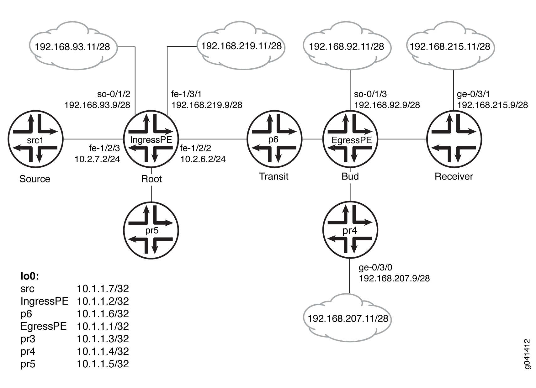 示例
示例
配置
过程
CLI 快速配置
要快速配置此示例,请复制以下命令,将其粘贴到文本文件中,删除所有换行符,更改详细信息,以便与网络配置匹配,然后将命令复制并粘贴到层次结构级别的 [edit] CLI 中。
设备 src1
set logical-systems src1 interfaces fe-1/2/0 unit 0 family inet address 10.2.7.7/24
set logical-systems src1 interfaces lo0 unit 0 family inet address 10.1.1.7/32
set logical-systems src1 protocols ospf area 0.0.0.0 interface all
设备入口 PE
set interfaces so-0/1/2 unit 0 family inet address 192.168.93.9/28
set interfaces fe-1/2/0 unit 0 family inet address 10.2.3.2/24
set interfaces fe-1/2/0 unit 0 family mpls
set interfaces fe-1/2/1 unit 0 family inet address 10.2.5.2/24
set interfaces fe-1/2/2 unit 0 family inet address 10.2.6.2/24
set interfaces fe-1/2/2 unit 0 family mpls
set interfaces fe-1/2/3 unit 0 family inet address 10.2.7.2/24
set interfaces fe-1/3/1 unit 0 family inet address 192.168.219.9/28
set interfaces lo0 unit 0 family inet address 10.1.1.2/32
set protocols igmp interface fe-1/2/1.0 version 3
set protocols igmp interface fe-1/2/1.0 static group 232.1.1.1 source 192.168.219.11
set protocols bgp group ibgp type internal
set protocols bgp group ibgp local-address 10.1.1.2
set protocols bgp group ibgp family inet any
set protocols bgp group ibgp family inet-vpn any
set protocols bgp group ibgp neighbor 10.1.1.3
set protocols bgp group ibgp neighbor 10.1.1.4
set protocols bgp group ibgp neighbor 10.1.1.1
set protocols ospf area 0.0.0.0 interface all
set protocols ldp interface fe-1/2/0.0
set protocols ldp interface fe-1/2/2.0
set protocols ldp interface lo0.0
set protocols ldp p2mp
set protocols pim mldp-inband-signalling policy mldppim-ex
set protocols pim rp static address 10.1.1.5
set protocols pim interface fe-1/3/1.0
set protocols pim interface lo0.0
set protocols pim interface fe-1/2/0.21
set protocols pim interface fe-1/2/3.0
set protocols pim interface fe-1/2/1.0
set protocols pim interface so-0/1/2.0
set policy-options policy-statement mldppim-ex term B from source-address-filter 192.168.0.0/24 orlonger
set policy-options policy-statement mldppim-ex term B from source-address-filter 192.168.219.11/32 orlonger
set policy-options policy-statement mldppim-ex term B then accept
set policy-options policy-statement mldppim-ex term A from source-address-filter 10.1.1.7/32 orlonger
set policy-options policy-statement mldppim-ex term A from source-address-filter 10.2.7.0/24 orlonger
set policy-options policy-statement mldppim-ex term A then accept
set routing-options autonomous-system 64510
设备出口 PE
set interfaces so-0/1/3 unit 0 point-to-point
set interfaces so-0/1/3 unit 0 family inet address 192.168.92.9/28
set interfaces fe-1/2/0 unit 0 family inet address 10.1.3.1/24
set interfaces fe-1/2/0 unit 0 family mpls
set interfaces fe-1/2/1 unit 0 family inet address 10.1.4.1/24
set interfaces fe-1/2/2 unit 0 family inet address 10.1.6.1/24
set interfaces fe-1/2/2 unit 0 family mpls
set interfaces fe-1/3/0 unit 0 family inet address 192.168.209.9/28
set interfaces lo0 unit 0 family inet address 10.1.1.1/32
set routing-options autonomous-system 64510
set protocols igmp interface fe-1/3/0.0 version 3
set protocols igmp interface fe-1/3/0.0 static group 232.1.1.1 group-count 3
set protocols igmp interface fe-1/3/0.0 static group 232.1.1.1 source 192.168.219.11
set protocols igmp interface fe-1/3/0.0 static group 227.1.1.1
set protocols igmp interface so-0/1/3.0 version 3
set protocols igmp interface so-0/1/3.0 static group 232.1.1.1 group-count 2
set protocols igmp interface so-0/1/3.0 static group 232.1.1.1 source 192.168.219.11
set protocols igmp interface so-0/1/3.0 static group 232.2.2.2 source 10.2.7.7
set protocols mpls interface fe-1/2/0.0
set protocols mpls interface fe-1/2/2.0
set protocols bgp group ibgp type internal
set protocols bgp group ibgp local-address 10.1.1.1
set protocols bgp group ibgp family inet any
set protocols bgp group ibgp neighbor 10.1.1.2
set protocols msdp local-address 10.1.1.1
set protocols msdp peer 10.1.1.5
set protocols ospf area 0.0.0.0 interface all
set protocols ospf area 0.0.0.0 interface fxp0.0 disable
set protocols ldp interface fe-1/2/0.0
set protocols ldp interface fe-1/2/2.0
set protocols ldp interface lo0.0
set protocols ldp p2mp
set protocols pim mldp-inband-signalling policy mldppim-ex
set protocols pim rp local address 10.1.1.1
set protocols pim rp local group-ranges 227.0.0.0/8
set protocols pim rp static address 10.1.1.4
set protocols pim rp static address 10.2.7.7 group-ranges 226.0.0.0/8
set protocols pim interface lo0.0
set protocols pim interface fe-1/3/0.0
set protocols pim interface fe-1/2/0.0
set protocols pim interface fe-1/2/1.0
set protocols pim interface so-0/1/3.0
set policy-options policy-statement mldppim-ex term B from source-address-filter 192.168.0.0/24 orlonger
set policy-options policy-statement mldppim-ex term B from source-address-filter 192.168.219.11/32 orlonger
set policy-options policy-statement mldppim-ex term B then p2mp-lsp-root address 10.1.1.2
set policy-options policy-statement mldppim-ex term B then accept
set policy-options policy-statement mldppim-ex term A from source-address-filter 10.2.7.0/24 orlonger
set policy-options policy-statement mldppim-ex term A then accept
设备 p6
set interfaces fe-1/2/0 unit 0 family inet address 10.1.6.6/24
set interfaces fe-1/2/0 unit 0 family mpls
set interfaces fe-1/2/1 unit 0 family inet address 10.2.6.6/24
set interfaces fe-1/2/1 unit 0 family mpls
set interfaces lo0 unit 0 family inet address 10.1.1.6/32
set interfaces lo0 unit 0 family mpls
set protocols ospf area 0.0.0.0 interface all
set protocols ldp interface fe-1/2/0.0
set protocols ldp interface fe-1/2/1.0
set protocols ldp interface lo0.0
set protocols ldp p2mp
设备 pr3
set interfaces ge-0/3/1 unit 0 family inet address 192.168.215.9/28
set interfaces fe-1/2/0 unit 0 family inet address 10.1.3.3/24
set interfaces fe-1/2/0 unit 0 family mpls
set interfaces fe-1/2/1 unit 0 family inet address 10.2.3.3/24
set interfaces fe-1/2/1 unit 0 family mpls
set interfaces lo0 unit 0 family inet address 10.1.1.3/32
set protocols igmp interface ge-0/3/1.0 version 3
set protocols igmp interface ge-0/3/1.0 static group 232.1.1.2 source 192.168.219.11
set protocols igmp interface ge-0/3/1.0 static group 232.2.2.2 source 10.2.7.7
set protocols bgp group ibgp local-address 10.1.1.3
set protocols bgp group ibgp type internal
set protocols bgp group ibgp neighbor 10.1.1.2
set protocols ospf area 0.0.0.0 interface all
set protocols ospf area 0.0.0.0 interface fe-1/2/1.0 metric 2
set protocols ldp interface fe-1/2/0.0
set protocols ldp interface fe-1/2/1.0
set protocols ldp interface lo0.0
set protocols ldp p2mp
set protocols pim mldp-inband-signalling policy mldppim-ex
set protocols pim interface fe-0/3/1.0
set protocols pim interface lo0.0
set policy-options policy-statement mldppim-ex term B from source-address-filter 192.168.0.0/24 orlonger
set policy-options policy-statement mldppim-ex term B from source-address-filter 192.168.219.11/32 orlonger
set policy-options policy-statement mldppim-ex term B then p2mp-lsp-root address 10.1.1.2
set policy-options policy-statement mldppim-ex term B then accept
set policy-options policy-statement mldppim-ex term B from source-address-filter 192.168.0.0/24 orlonger
set policy-options policy-statement mldppim-ex term B from source-address-filter 192.168.219.11/32 orlonger
set policy-options policy-statement mldppim-ex term B from source-address-filter 10.2.7.7/32 orlonger
set policy-options policy-statement mldppim-ex term B then p2mp-lsp-root address 10.1.1.2
set policy-options policy-statement mldppim-ex term B then accept
set routing-options autonomous-system 64510
设备 pr4
set interfaces ge-0/3/0 unit 0 family inet address 192.168.207.9/28
set interfaces fe-1/2/0 unit 0 family inet address 10.1.4.4/24
set interfaces fe-1/2/0 unit 0 family iso
set interfaces lo0 unit 0 family inet address 10.1.1.4/32
set protocols igmp interface ge-0/3/0.0 version 3
set protocols igmp interface ge-0/3/0.0 static group 232.1.1.2 source 192.168.219.11
set protocols igmp interface ge-0/3/0.0 static group 225.1.1.1
set protocols bgp group ibgp local-address 10.1.1.4
set protocols bgp group ibgp type internal
set protocols bgp group ibgp neighbor 10.1.1.2
set protocols msdp local-address 10.1.1.4
set protocols msdp peer 10.1.1.5
set protocols ospf area 0.0.0.0 interface all
set protocols pim rp local address 10.1.1.4
set protocols pim interface ge-0/3/0.0
set protocols pim interface lo0.0
set protocols pim interface fe-1/2/0.0
set routing-options autonomous-system 64510
设备 pr5
set interfaces fe-1/2/0 unit 0 family inet address 10.2.5.5/24
set interfaces lo0 unit 0 family inet address 10.1.1.5/24
set protocols igmp interface lo0.0 version 3
set protocols igmp interface lo0.0 static group 232.1.1.1 source 192.168.219.11
set protocols msdp local-address 10.1.1.5
set protocols msdp peer 10.1.1.4
set protocols msdp peer 10.1.1.1
set protocols ospf area 0.0.0.0 interface all
set protocols pim rp local address 10.1.1.5
set protocols pim interface all
分步程序
下面的示例要求您在各个配置层级中进行导航。有关导航 CLI 的信息,请参阅 《CLI 用户指南》中的在配置模式下使用 CLI 编辑器。
要配置设备 EgressPE:
配置接口。
在面向核心的接口上启用 MPLS。在出口下一跃点上,无需启用 MPLS。
[edit interfaces]
user@EgressPE# set fe-1/2/0 unit 0 family inet address 10.1.3.1/24
user@EgressPE# set fe-1/2/0 unit 0 family mpls
user@EgressPE# set fe-1/2/2 unit 0 family inet address 10.1.6.1/24
user@EgressPE# set fe-1/2/2 unit 0 family mpls
user@EgressPE# set so-0/1/3 unit 0 point-to-point
user@EgressPE# set so-0/1/3 unit 0 family inet address 192.168.92.9/28
user@EgressPE# set fe-1/2/1 unit 0 family inet address 10.1.4.1/24
user@EgressPE# set fe-1/3/0 unit 0 family inet address 192.168.209.9/28
user@EgressPE# set lo0 unit 0 family inet address 10.1.1.1/32
在出口接口上配置 IGMP。
出于测试目的,此示例包含静态组地址和源地址。
[edit protocols igmp]
user@EgressPE# set interface fe-1/3/0.0 version 3
user@EgressPE# set interface fe-1/3/0.0 static group 232.1.1.1 group-count 3
user@EgressPE# set interface fe-1/3/0.0 static group 232.1.1.1 source 192.168.219.11
user@EgressPE# set interface fe-1/3/0.0 static group 227.1.1.1
user@EgressPE# set interface so-0/1/3.0 version 3
user@EgressPE# set interface so-0/1/3.0 static group 232.1.1.1 group-count 2
user@EgressPE# set interface so-0/1/3.0 static group 232.1.1.1 source 192.168.219.11
user@EgressPE# set interface so-0/1/3.0 static group 232.2.2.2 source 10.2.7.7
在面向核心的接口上配置 MPLS。
[edit protocols mpls]
user@EgressPE# set interface fe-1/2/0.0
user@EgressPE# set interface fe-1/2/2.0
配置 BGP。
BGP 是一种由策略驱动的协议,因此还要配置和应用任何所需的路由策略。
例如,您可能希望将静态路由导出到 BGP。
[edit protocols bgp group ibgp]
user@EgressPE# set type internal
user@EgressPE# set local-address 10.1.1.1
user@EgressPE# set family inet any
user@EgressPE# set neighbor 10.1.1.2
(选答)配置与设备 pr5 的 MSDP 对等连接,以便互连不同的 PIM 域,从而启用冗余 RP。
[edit protocols msdp]
user@EgressPE# set local-address 10.1.1.1
user@EgressPE# set peer 10.1.1.5
配置 OSPF。
[edit protocols ospf area 0.0.0.0]
user@EgressPE# set interface all
user@EgressPE# set interface fxp0.0 disable
在面向核心的接口和环路接口上配置 LDP。
[edit protocols ldp]
user@EgressPE# set interface fe-1/2/0.0
user@EgressPE# set interface fe-1/2/2.0
user@EgressPE# set interface lo0.0
启用点对多点 MPLS LSP。
[edit protocols ldp]
user@EgressPE# set p2mp
在下游接口上配置 PIM。
[edit protocols pim]
user@EgressPE# set interface lo0.0
user@EgressPE# set interface fe-1/3/0.0
user@EgressPE# set interface fe-1/2/1.0
user@EgressPE# set interface so-0/1/3.0
配置 RP 设置,因为此设备用作 PIM 汇聚点 (RP)。
[edit protocols pim]
user@EgressPE# set rp local address 10.1.1.1
user@EgressPE# set rp local group-ranges 227.0.0.0/8
user@EgressPE# set rp static address 10.1.1.4
user@EgressPE# set rp static address 10.2.7.7 group-ranges 226.0.0.0/8
启用 M-LDP 带内信令并设置关联策略。
[edit protocols pim]
user@EgressPE# set mldp-inband-signalling policy mldppim-ex
配置指定点对多点 LSP 的根地址和关联源地址的路由策略。
[edit policy-options policy-statement mldppim-ex]
user@EgressPE# set term B from source-address-filter 192.168.0.0/24 orlonger
user@EgressPE# set term B from source-address-filter 192.168.219.11/32 orlonger
user@EgressPE# set term B then p2mp-lsp-root address 10.1.1.2
user@EgressPE# set term B then accept
user@EgressPE# set term A from source-address-filter 10.2.7.0/24 orlonger
user@EgressPE# set term A then accept
配置自治系统 (AS) ID。
[edit routing-options]
user@EgressPE# set autonomous-system 64510
结果
在配置模式下,输入 show interfaces、 show protocols、 show policy-options和 show routing-options 命令以确认您的配置。如果输出未显示预期的配置,请重复此示例中的说明以更正配置。
设备出口 PE
user@EgressPE# show interfaces
so-0/1/3 {
    unit 0 {
        point-to-point;
        family inet {
            address 192.168.92.9/28;
        }
    }
}
fe-1/2/0 {
    unit 0 {
        family inet {
            address 10.1.3.1/24;
        }
        family mpls;
    }
}
fe-1/2/1 {
    unit 0 {
        family inet {
            address 10.1.4.1/24;
        }
    }
}
fe-1/2/2 {
    unit 0 {
        family inet {
            address 10.1.6.1/24;
        }
        family mpls;
    }
}
fe-1/3/0 {
    unit 0 {
        family inet {
            address 192.168.209.9/28;
        }
    }
}
lo0 {
    unit 0 {
        family inet {
            address 10.1.1.1/32;
        }
    }
}
user@EgressPE# show protocols
igmp {
    interface fe-1/3/0.0 {
        version 3;
        static {
            group 232.1.1.1 {
                group-count 3;
                source 192.168.219.11;
            }
            group 227.1.1.1;
        }
    }
    interface so-0/1/3.0 {
        version 3;
        static {
            group 232.1.1.1 {
                group-count 2;
                source 192.168.219.11;
            }
            group 232.2.2.2 {
                source 10.2.7.7;
            }
        }
    }
}
mpls {
    interface fe-1/2/0.0;
    interface fe-1/2/2.0;
}
bgp {
    group ibgp {
        type internal;
        local-address 10.1.1.1;
        family inet {
            any;
        }
        neighbor 10.1.1.2;
    }
}
msdp {
    local-address 10.1.1.1;
    peer 10.1.1.5;
}
ospf {
    area 0.0.0.0 {
        interface all;
        interface fxp0.0 {
            disable;
        }
    }
}
ldp {
    interface fe-1/2/0.0;
    interface fe-1/2/2.0;
    interface lo0.0;
    p2mp;
}
pim {
    mldp-inband-signalling {
        policy mldppim-ex;
    }
    rp {
        local {
            address 10.1.1.1;
            group-ranges {
                227.0.0.0/8;
            }
        }
        static {
            address 10.1.1.4;
            address 10.2.7.7 {
                group-ranges {
                    226.0.0.0/8;
                }
            }
        }
    }
    interface lo0.0;
    interface fe-1/3/0.0;
    interface fe-1/2/0.0;
    interface fe-1/2/1.0;
    interface so-0/1/3.0;
}
user@EgressPE# show policy-options
policy-statement mldppim-ex {
    term B {
        from {
            source-address-filter 192.168.0.0/24 orlonger;
            source-address-filter 192.168.219.11/32 orlonger;
        }
        then {
            p2mp-lsp-root {
                address 10.1.1.2;
            }
            accept;
        }
    }
    term A {
        from {
            source-address-filter 10.2.7.0/24 orlonger;
        }
        then accept;
    }
}
user@EgressPE# show routing-options
autonomous-system 64510;
同样,配置其他出口设备。
如果完成设备配置,请从配置模式进入。commit
验证
确认配置工作正常。
检查 PIM 加入状态
目的
显示有关 PIM 连接状态的信息,以验证 M-LDP 带内上行和下行详细信息。在入口设备上, show pim join extensive 将显示 Pseudo-MLDP 下游接口的命令。在出口时, show pim join extensive 将显示 Pseudo-MLDP 上游接口的命令。
行动
在操作模式下,输入命令 show pim join extensive 。
user@IngressPE> show pim join extensive

Instance: PIM.master Family: INET
R = Rendezvous Point Tree, S = Sparse, W = Wildcard

Group: 232.1.1.1
    Source: 192.168.219.11
    Flags: sparse,spt
    Upstream interface: fe-1/3/1.0
    Upstream neighbor: Direct
    Upstream state: Local Source
    Keepalive timeout:
    Uptime: 1d 23:00:12
    Downstream neighbors:
        Interface: Pseudo-MLDP
        Interface: fe-1/2/1.0
            10.2.5.2 State: Join Flags: S   Timeout: Infinity
            Uptime: 1d 23:00:12 Time since last Join: 1d 23:00:12

Group: 232.1.1.2
    Source: 192.168.219.11
    Flags: sparse,spt
    Upstream interface: fe-1/3/1.0
    Upstream neighbor: Direct
    Upstream state: Local Source
    Keepalive timeout:
    Uptime: 1d 22:59:59
    Downstream neighbors:
        Interface: Pseudo-MLDP

Group: 232.1.1.3
    Source: 192.168.219.11
    Flags: sparse,spt
    Upstream interface: fe-1/3/1.0
    Upstream neighbor: Direct
    Upstream state: Local Source
    Keepalive timeout:
    Uptime: 1d 22:07:31
    Downstream neighbors:
        Interface: Pseudo-MLDP

Group: 232.2.2.2
    Source: 10.2.7.7
    Flags: sparse,spt
    Upstream interface: fe-1/2/3.0
    Upstream neighbor: Direct
    Upstream state: Local Source
    Keepalive timeout:
    Uptime: 1d 22:59:59
    Downstream neighbors:
        Interface: Pseudo-MLDP


user@EgressPE> show pim join extensive

Instance: PIM.master Family: INET
R = Rendezvous Point Tree, S = Sparse, W = Wildcard

Group: 227.1.1.1
    Source: *
    RP: 10.1.1.1
    Flags: sparse,rptree,wildcard
    Upstream interface: Local
    Upstream neighbor: Local
    Upstream state: Local RP
    Uptime: 1d 23:14:21
    Downstream neighbors:
        Interface: fe-1/3/0.0
            192.168.209.9 State: Join Flags: SRW  Timeout: Infinity
            Uptime: 1d 23:14:21 Time since last Join: 1d 20:12:35

Group: 232.1.1.1
    Source: 192.168.219.11
    Flags: sparse,spt
    Upstream protocol: MLDP
    Upstream interface: Pseudo MLDP
    Upstream neighbor: MLDP LSP root <10.1.1.2>
    Upstream state: Join to Source
    Keepalive timeout:
    Uptime: 1d 23:14:22
    Downstream neighbors:
        Interface: so-0/1/3.0
            192.168.92.9 State: Join Flags: S   Timeout: Infinity
            Uptime: 1d 20:12:35 Time since last Join: 1d 20:12:35
    Downstream neighbors:
        Interface: fe-1/3/0.0
            192.168.209.9 State: Join Flags: S   Timeout: Infinity
            Uptime: 1d 20:12:35 Time since last Join: 1d 20:12:35

Group: 232.1.1.2
    Source: 192.168.219.11
    Flags: sparse,spt
    Upstream protocol: MLDP
    Upstream interface: Pseudo MLDP
    Upstream neighbor: MLDP LSP root <10.1.1.2>
    Upstream state: Join to Source
    Keepalive timeout:
    Uptime: 1d 23:14:22
    Downstream neighbors:
        Interface: so-0/1/3.0
            192.168.92.9 State: Join Flags: S   Timeout: Infinity
            Uptime: 1d 20:12:35 Time since last Join: 1d 20:12:35
    Downstream neighbors:
        Interface: fe-1/2/1.0
            10.1.4.4 State: Join Flags: S Timeout: 198
            Uptime: 1d 22:59:59 Time since last Join: 00:00:12
    Downstream neighbors:
        Interface: fe-1/3/0.0
            192.168.209.9 State: Join Flags: S   Timeout: Infinity
            Uptime: 1d 20:12:35 Time since last Join: 1d 20:12:35

Group: 232.1.1.3
    Source: 192.168.219.11
    Flags: sparse,spt
    Upstream protocol: MLDP
    Upstream interface: Pseudo MLDP
    Upstream neighbor: MLDP LSP root <10.1.1.2>
    Upstream state: Join to Source
    Keepalive timeout:
    Uptime: 1d 20:12:35
    Downstream neighbors:
        Interface: fe-1/3/0.0
            192.168.209.9 State: Join Flags: S   Timeout: Infinity
            Uptime: 1d 20:12:35 Time since last Join: 1d 20:12:35

Group: 232.2.2.2
    Source: 10.2.7.7
    Flags: sparse,spt
    Upstream protocol: MLDP
    Upstream interface: Pseudo MLDP
    Upstream neighbor: MLDP LSP root <10.1.1.2>
    Upstream state: Join to Source
    Keepalive timeout:
    Uptime: 1d 20:12:35
    Downstream neighbors:
        Interface: so-0/1/3.0
            192.168.92.9 State: Join Flags: S   Timeout: Infinity
            Uptime: 1d 20:12:35 Time since last Join: 1d 20:12:35

user@pr3> show pim join extensive

Instance: PIM.master Family: INET
R = Rendezvous Point Tree, S = Sparse, W = Wildcard

Group: 232.1.1.2
    Source: 192.168.219.11
    Flags: sparse,spt
    Upstream protocol: MLDP
    Upstream interface: Pseudo MLDP
    Upstream neighbor: MLDP LSP root <10.1.1.2>
    Upstream state: Join to Source
    Keepalive timeout:
    Uptime: 1d 20:14:40
    Downstream neighbors:
        Interface: Pseudo-GMP
            ge-0/3/1.0

Group: 232.2.2.2
    Source: 10.2.7.7
    Flags: sparse,spt
    Upstream protocol: MLDP
    Upstream interface: Pseudo MLDP
    Upstream neighbor: MLDP LSP root <10.1.1.2>
    Upstream state: Join to Source
    Keepalive timeout:
    Uptime: 1d 20:14:40
    Downstream neighbors:
        Interface: Pseudo-GMP
            ge-0/3/1.0


user@pr4> show pim join extensive
Instance: PIM.master Family: INET
R = Rendezvous Point Tree, S = Sparse, W = Wildcard

Group: 225.1.1.1
    Source: *
    RP: 10.1.1.4
    Flags: sparse,rptree,wildcard
    Upstream interface: Local
    Upstream neighbor: Local
    Upstream state: Local RP
    Uptime: 1d 23:13:43
    Downstream neighbors:
        Interface: ge-0/3/0.0
            192.168.207.9 State: Join Flags: SRW  Timeout: Infinity
            Uptime: 1d 23:13:43 Time since last Join: 1d 23:13:43

Group: 232.1.1.2
    Source: 192.168.219.11
    Flags: sparse,spt
    Upstream interface: fe-1/2/0.0
    Upstream neighbor: 10.1.4.1
    Upstream state: Local RP, Join to Source
    Keepalive timeout: 0
    Uptime: 1d 23:13:43
    Downstream neighbors:
        Interface: ge-0/3/0.0
            192.168.207.9 State: Join Flags: S   Timeout: Infinity
            Uptime: 1d 23:13:43 Time since last Join: 1d 23:13:43


user@pr5> show pim join extensive
            ge-0/3/1.0

Instance: PIM.master Family: INET
R = Rendezvous Point Tree, S = Sparse, W = Wildcard

Instance: PIM.master Family: INET6
R = Rendezvous Point Tree, S = Sparse, W = Wildcard
检查 PIM 源
目的
验证 PIM 源是否具有预期的 M-LDP 带内上行和下游详细信息。
行动
在操作模式下,输入命令 show pim source 。
user@IngressPE> show pim source

Instance: PIM.master Family: INET

Source 10.1.1.1
    Prefix 10.1.1.1/32
    Upstream interface Local
    Upstream neighbor Local

Source 10.2.7.7
    Prefix 10.2.7.0/24
    Upstream protocol MLDP
    Upstream interface Pseudo MLDP
    Upstream neighbor MLDP LSP root <10.1.1.2>

Source 192.168.219.11
    Prefix 192.168.219.0/28
    Upstream protocol MLDP
    Upstream interface Pseudo MLDP
    Upstream neighbor MLDP LSP root <10.1.1.2>
user@EgressPE> show pim source
Instance: PIM.master Family: INET

Source 10.2.7.7
    Prefix 1.2.7.0/24
    Upstream interface fe-1/2/3.0
    Upstream neighbor 10.2.7.2

Source 10.2.7.7
    Prefix 10.2.7.0/24
    Upstream interface fe-1/2/3.0
    Upstream neighbor Direct

Source 192.168.219.11
    Prefix 192.168.219.0/28
    Upstream interface fe-1/3/1.0
    Upstream neighbor 192.168.219.9

Source 192.168.219.11
    Prefix 192.168.219.0/28
    Upstream interface fe-1/3/1.0
    Upstream neighbor Direct
user@pr3> show pim source

Instance: PIM.master Family: INET

Source 10.2.7.7
    Prefix 1.2.7.0/24
    Upstream protocol MLDP
    Upstream interface Pseudo MLDP
    Upstream neighbor MLDP LSP root <10.1.1.2>

Source 192.168.219.11
    Prefix 192.168.219.0/28
    Upstream protocol MLDP
    Upstream interface Pseudo MLDP
    Upstream neighbor MLDP LSP root <10.1.1.2>
user@pr4> show pim source
Instance: PIM.master Family: INET

Source 10.1.1.4
    Prefix 10.1.1.4/32
    Upstream interface Local
    Upstream neighbor Local

Source 192.168.219.11
    Prefix 192.168.219.0/28
    Upstream interface fe-1/2/0.0
    Upstream neighbor 10.1.4.1
检查 LDP 数据库
目的
确保命令 show ldp database 显示预期的根到 (S,G) 绑定。
行动
user@IngressPE> show ldp database
Input label database, 10.255.2.227:0--10.1.1.3:0
  Label     Prefix
 300096      10.1.1.2/32
      3      10.1.1.3/32
 299856      10.1.1.6/32
 299776      10.255.2.227/32

Output label database, 10.255.2.227:0--10.1.1.3:0
  Label     Prefix
 300144      10.1.1.2/32
 299776      10.1.1.3/32
 299856      10.1.1.6/32
      3      10.255.2.227/32

Input label database, 10.255.2.227:0--10.1.1.6:0
  Label     Prefix
 299936      10.1.1.2/32
 299792      10.1.1.3/32
      3      10.1.1.6/32
 299776      10.255.2.227/32

Output label database, 10.255.2.227:0--10.1.1.6:0
  Label     Prefix
 300144      10.1.1.2/32
 299776      10.1.1.3/32
 299856      10.1.1.6/32
      3      10.255.2.227/32
 300432      P2MP root-addr 10.1.1.2, grp: 232.2.2.2, src: 10.2.7.7
 300288      P2MP root-addr 10.1.1.2, grp: 232.1.1.1, src: 192.168.219.11
 300160      P2MP root-addr 10.1.1.2, grp: 232.1.1.2, src: 192.168.219.11
 300480      P2MP root-addr 10.1.1.2, grp: 232.1.1.3, src: 192.168.219.11
user@EgressPE> show ldp database

Input label database, 10.1.1.2:0--10.1.1.3:0
  Label     Prefix
 300096      10.1.1.2/32
      3      10.1.1.3/32
 299856      10.1.1.6/32
 299776      10.255.2.227/32
 300144      P2MP root-addr 10.1.1.2, grp: 232.2.2.2, src: 10.2.7.7
 300128      P2MP root-addr 10.1.1.2, grp: 232.1.1.2, src: 192.168.219.11

Output label database, 10.1.1.2:0--10.1.1.3:0
  Label     Prefix
      3      10.1.1.2/32
 299776      10.1.1.3/32
 299808      10.1.1.6/32
 299792      10.255.2.227/32

Input label database, 10.1.1.2:0--10.1.1.6:0
  Label     Prefix
 299936      10.1.1.2/32
 299792      10.1.1.3/32
      3      10.1.1.6/32
 299776      10.255.2.227/32
 300128      P2MP root-addr 10.1.1.2, grp: 232.2.2.2, src: 10.2.7.7
 299984      P2MP root-addr 10.1.1.2, grp: 232.1.1.1, src: 192.168.219.11
 299952      P2MP root-addr 10.1.1.2, grp: 232.1.1.2, src: 192.168.219.11
 300176      P2MP root-addr 10.1.1.2, grp: 232.1.1.3, src: 192.168.219.11
 300192      P2MP root-addr 10.1.1.2, grp: ff3e::1:2, src: 2001:db8:abcd::10:2:7:7

Output label database, 10.1.1.2:0--10.1.1.6:0
  Label     Prefix
      3      10.1.1.2/32
 299776      10.1.1.3/32
 299808      10.1.1.6/32
 299792      10.255.2.227/32
-----

logical-system: default

Input label database, 10.255.2.227:0--10.1.1.3:0
  Label     Prefix
 300096      10.1.1.2/32
      3      10.1.1.3/32
 299856      10.1.1.6/32
 299776      10.255.2.227/32

Output label database, 10.255.2.227:0--10.1.1.3:0
  Label     Prefix
 300144      10.1.1.2/32
 299776      10.1.1.3/32
 299856      10.1.1.6/32
      3      10.255.2.227/32

Input label database, 10.255.2.227:0--10.1.1.6:0
  Label     Prefix
 299936      10.1.1.2/32
 299792      10.1.1.3/32
      3      10.1.1.6/32
 299776      10.255.2.227/32

Output label database, 10.255.2.227:0--10.1.1.6:0
  Label     Prefix
 300144      10.1.1.2/32
 299776      10.1.1.3/32
 299856      10.1.1.6/32
      3      10.255.2.227/32
 300432      P2MP root-addr 10.1.1.2, grp: 232.2.2.2, src: 10.2.7.7
 300288      P2MP root-addr 10.1.1.2, grp: 232.1.1.1, src: 192.168.219.11
 300160      P2MP root-addr 10.1.1.2, grp: 232.1.1.2, src: 192.168.219.11
 300480      P2MP root-addr 10.1.1.2, grp: 232.1.1.3, src: 192.168.219.11
 300496      P2MP root-addr 10.1.1.2, grp: ff3e::1:2, src: 2001:db8:abcd::10:2:7:7
user@p6> show ldp database

Input label database, 10.1.1.6:0--10.1.1.2:0
  Label     Prefix
      3      10.1.1.2/32
 299776      10.1.1.3/32
 299808      10.1.1.6/32

Output label database, 10.1.1.6:0--10.1.1.2:0
  Label     Prefix
 299776      10.1.1.2/32
 299792      10.1.1.3/32
      3      10.1.1.6/32
user@pr3> show ldp database

Input label database, 10.1.1.3:0--10.1.1.2:0
  Label     Prefix
      3      10.1.1.2/32
 299776      10.1.1.3/32
 299808      10.1.1.6/32
 299792      10.255.2.227/32

Output label database, 10.1.1.3:0--10.1.1.2:0
  Label     Prefix
 300096      10.1.1.2/32
      3      10.1.1.3/32
 299856      10.1.1.6/32
 299776      10.255.2.227/32
 300144      P2MP root-addr 10.1.1.2, grp: 232.2.2.2, src: 10.2.7.7
 300128      P2MP root-addr 10.1.1.2, grp: 232.1.1.2, src: 192.168.219.11

Input label database, 10.1.1.3:0--10.255.2.227:0
  Label     Prefix
 300144      10.1.1.2/32
 299776      10.1.1.3/32
 299856      10.1.1.6/32
      3      10.255.2.227/32

Output label database, 10.1.1.3:0--10.255.2.227:0
  Label     Prefix
 300096      10.1.1.2/32
      3      10.1.1.3/32
 299856      10.1.1.6/32
 299776      10.255.2.227/32
查找 MPLS 标签的路由信息
目的
显示点对多点 FEC 信息。
行动
user@EgressPE> show route label 299808 detail

mpls.0: 14 destinations, 14 routes (14 active, 0 holddown, 0 hidden)
299808 (1 entry, 1 announced)
        *LDP    Preference: 9
                Next hop type: Flood
                Address: 0x931922c
                Next-hop reference count: 3
                Next hop type: Router, Next hop index: 1109
                Address: 0x9318b0c
                Next-hop reference count: 2
                Next hop: via so-0/1/3.0
                Label operation: Pop
                Next hop type: Router, Next hop index: 1110
                Address: 0x93191e0
                Next-hop reference count: 2
                Next hop: 192.168.209.11 via fe-1/3/0.0
                Label operation: Pop
                State: **Active Int AckRequest>
                Local AS:    10
                Age: 13:08:15   Metric: 1
                Validation State: unverified
                Task: LDP
                Announcement bits (1): 0-KRT
                AS path: I
                FECs bound to route: P2MP root-addr 10.1.1.2, grp: 232.1.1.1, src: 192.168.219.11
检查 LDP 流量统计信息
目的
监控点对多点 LSP 的数据流量统计信息。
行动
user@EgressPE> show ldp traffic-statistics p2mp
P2MP FEC Statistics:

FEC(root_addr:lsp_id/grp,src)     Nexthop              Packets             Bytes Shared
10.1.1.2:232.2.2.2,10.2.7.7         so-0/1/3.0                 0                 0 No
10.1.1.2:232.1.1.1,192.168.219.11  so-0/1/3.0                 0                 0 No
                                  fe-1/3/0.0                 0                 0 No
10.1.1.2:232.1.1.2,192.168.219.11  so-0/1/3.0                 0                 0 No
                                  fe-1/3/0.0                 0                 0 No
                                  lt-1/2/0.14                0                 0 No
10.1.1.2:232.1.1.3,192.168.219.11  fe-1/3/0.0                 0                 0 No
10.1.1.2:ff3e::1:2,2001:db8:abcd::1:2:7:7   fe-1/3/0.0                 0                 0 No
将分段路由的客户端和服务器映射到 LDP 互操作性
分段路由映射服务器和客户端支持支持在运行 LDP 和分段路由(SR 或 SPRING)的网络孤岛之间实现互操作性。在从 LDP 迁移到 SR 期间,这种互操作性非常有用。在过渡期间,可能会存在孤岛(或域),其设备的要么仅支持 LDP,要么仅支持分段路由。若要使这些设备互连,需要 LDP 分段路由映射服务器 (SRMS) 和分段路由映射客户端 (SRMC) 功能。您可以在分段路由网络中的设备上启用这些服务器和客户端功能。
OSPF 或 IS-IS 支持 SR 映射服务器和客户端功能。
分段路由到 LDP 互操作性概述
图 22 显示了一个简单的 LDP 网络拓扑,说明了分段路由设备与 LDP 设备的互操作性的工作原理。请记住,OSPF 和 IS-IS 都受支持,因此目前我们将与 IGP 保持无关。示例拓扑中有六台设备(R1 到 R6)位于正在从 LDP 迁移到分段路由的网络中。
在拓扑中,设备 R1、R2 和 R3 仅配置为分段路由。设备 R5 和 R6 属于传统 LDP 域,当前不支持 SR。设备 R4 同时支持 LDP 路由和分段路由。将显示所有设备的环路地址。这些环路在 LDP 域中作为出口 FEC 播发,在 SR 域中作为 SR 节点 ID 播发。互操作性基于将 LDP FEC 映射到 SR 节点 ID(反之亦然)。
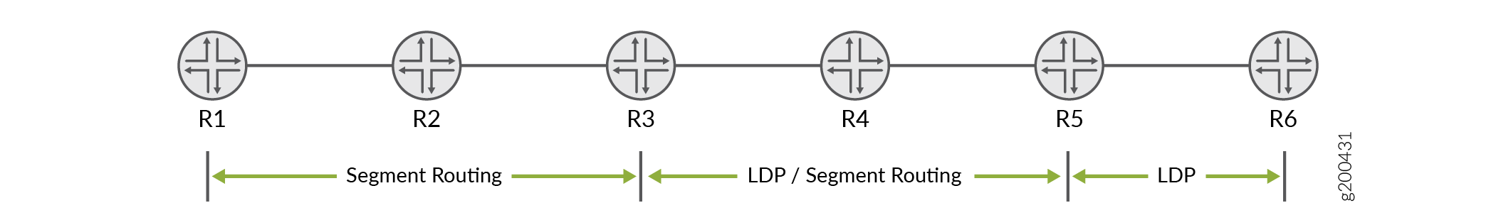 的分段路由示例
要使 R1 与 R6 互连,需要 LDP 分段路由映射服务器 (SRMS) 和分段路由映射客户端 (SRMC)。通过以单向方式查看流量,可以更容易地理解 SRMS 和 SRMC 的作用。根据 图 22,我们判断从左向右流动的流量始于 SR 域,终止于 LDP 域。同样,从右向左流动的流量从 LDP 域开始,在 SR 域中终止。
SRMS 提供从左到右方向拼接流量所需的信息。SRMC 为从右向左流动的流量提供映射。
- 从左到右 流量:分段路由映射服务器
SRMS 有助于在 SR 和 LDP 域之间进行 LSP 拼接。服务器将 LDP FEC 映射到 SR 节点 ID。您可以配置要映射在层次结构级别下的
[edit routing-options source-packet-routing]LDP FEC。通常,您需要映射所有 LDP 节点环路地址才能实现完全连接。如下所示,您可以在单个范围语句中映射连续前缀。如果 LDP 节点环路不连续,则需要定义多个映射语句。您可以在 或
[edit protocols isis]层次结构级别下[edit protocols ospf]应用 SRMS 映射配置。此选择取决于使用的 IGP。请注意,SR 和 LDP 节点共享一个通用的单区域/级别 IGP 路由域。SRMS 会生成扩展前缀列表 LSA(如果为 IS-IS,则为 LSP)。此 LSA 中的信息允许 SR 节点将 LDP 前缀 (FEC) 映射到 SR 节点 ID。LDP 前缀的映射路由安装在 SR 节点的路由表中
inet.3mpls.0,以方便 LSP 从左到右方向的流量入口和拼接操作。扩展 LSA(或 LSP)在整个(单个)IGP 区域中泛洪。这意味着您可以自由地将 SRMS 配置放置在 SR 域中的任何路由器上。SRMS 节点不必运行 LDP。
- 从右到左的流量:分段路由映射客户端
要从右到左方向(即从 LDP 岛到 SR 岛)进行互操作,只需在同时使用 SR 和 LDP 的节点上启用分段路由映射客户端功能。在我们的示例中,这是 R4。可以使用层次结构中的
[edit protocols ldp]语句激活mapping-clientSRMC 功能。SRMC 配置会自动激活 LDP 出口策略,以将 SR 域的节点和前缀 SID 播发为 LDP 出口 FEC。这为 LDP 节点提供了到 SR 域中节点的 LSP 可达性。
- 必须在同时连接到 SR 和 LSP 域的路由器上配置 SRMC 功能。如果需要,同一节点也可用作 SRMS。
使用 OSPF 实现到 LDP 的分段路由互操作性
请参阅 图 22,假设设备 R2(在分段路由网络中)是 SRMS。
-
定义 SRMS 函数:
[edit routing-options source-packet-routing ]
user@R2# set mapping-server-entry ospf-mapping-server prefix-segment-range ldp-lo0s start-prefix 192.168.0.5
user@R2# set mapping-server-entry ospf-mapping-server prefix-segment-range ldp-lo0s start-index 1000
user@R2# set mapping-server-entry ospf-mapping-server prefix-segment-range ldp-lo0s size 2
此配置为示例拓扑中的两个 LDP 设备环路地址创建一个映射块。映射到 R5 环路的初始分段 ID (SID) 索引为
1000。指定大小2会导致 SID 索引 10001 映射到 R6 的环路地址。注意:用作 的
start-prefixIP 地址是 LDP 网络中设备的环路地址(本例中为 R5)。要实现完全连接,您必须将 LDP 路由器的所有环路地址映射到 SR 域中。如果环路地址是连续的,则可以使用单个prefix-segment-range语句执行此操作。非连续环路需要定义多个前缀映射语句。我们的示例使用连续环路,因此上面显示了一个单环
prefix-segment-range路。以下是多个映射的示例,用于支持两个 LDP 节点使用非连续环路寻址的情况:[edit routing-options source-packet-routing] show mapping-server-entry map-server-name { prefix-segment-range lo1 { start-prefix 192.168.0.5/32; start-index 1000; size 1; } prefix-segment-range lo2 { start-prefix 192.168.0.10/32; start-index 2000; size 1; } } } -
接下来,为用于泛洪映射前缀的扩展 LSA 配置 OSPF 支持。
[edit protocols]
user@R2# set ospf source-packet-routing mapping-server ospf-mapping-server
在设备 R2 上提交映射服务器配置后,扩展前缀范围 TLV 将泛洪到 OSPF 区域。支持分段路由的设备(R1、R2 和 R3)会为指定的环路地址(本例中的 R5 和 R6)安装带有分段 ID (SID) 索引的 OSPF 分段路由路由。分段路由设备也会在路由表中
mpls.0更新 SID 索引。 -
启用 SRMC 功能。对于我们的示例拓扑,您必须在 R4 上启用 SRMC 功能。
[edit protocols]
user@R4# set ldp sr-mapping-client
在设备 R4 上提交映射客户端配置后,SR 节点 ID 和标签块将作为出口 FEC 播发至 路由器 R5,然后 R5 再将其重新播发至 R6。
从 Junos OS 19.1R1 开始支持使用 OSPF 拼接分段路由和 LDP 下一跃点。
Unsupported Features and Functionality for Segment Routing interoperability with LDP using OSPF
-
不支持 IPv6 前缀。
-
不支持跨 AS 边界(AS 间)使用大量 OSPF 扩展前缀不透明 LSA。
-
不支持区域间 LDP 映射服务器功能。
-
不支持扩展前缀不透明 LSA 的 ABR 功能。
-
不支持扩展前缀不透明 LSA 的 ASBR 功能。
-
不支持分段路由映射服务器首选项 TLV。
使用 IS-IS 的分段路由与 LDP 的互操作性
请参阅 图 22,假设设备 R2(在分段路由网络中)是 SRMS。为映射功能添加了以下配置:
-
定义 SRMS 函数:
[edit routing-options source-packet-routing ]
user@R2# set mapping-server-entry isis-mapping-server prefix-segment-range ldp-lo0s start-prefix 192.168.0.5
user@R2# set mapping-server-entry isis-mapping-server prefix-segment-range ldp-lo0s start-index 1000
user@R2# set mapping-server-entry isis-mapping-server prefix-segment-range ldp-lo0s size 2
此配置为示例拓扑中的两个 LDP 设备环路地址创建一个映射块。映射到 R5 环路的初始分段 ID (SID) 索引为
1000。指定大小2会导致 SID 索引 10001 映射到 R6 的环路地址。注意:用作 的
start-prefixIP 地址是 LDP 网络中设备的环路地址(本例中为 R5)。为了实现完全连接,您必须映射 SR 域中 LDP 路由器的所有环路地址。如果环路地址是连续的,您可以使用语句执行此操作prefix-segment-range。非连续环路需要定义多个映射语句。我们的示例使用连续环路,因此上面显示了一个单环
prefix-segment-range路。以下是前缀映射示例,用于处理两个具有非连续环路寻址的 LDP 路由器的情况:[edit routing-options source-packet-routing] show mapping-server-entry map-server-name { prefix-segment-range lo1 { start-prefix 192.168.0.5/32; start-index 1000; size 1; } prefix-segment-range lo2 { start-prefix 192.168.0.10/32; start-index 2000; size 1; } } } -
接下来,为用于泛洪映射前缀的扩展 LSP 配置 IS-IS 支持。
[edit protocols]
user@R2# set isis source-packet-routing mapping-server isis-mapping-server
在设备 R2 上提交映射服务器配置后,扩展前缀范围 TLV 将泛洪到 OSPF 区域。支持分段路由的设备(R1、R2 和 R3)会为指定的环路地址(本例中的 R5 和 R6)安装带有分段 ID (SID) 索引的 IS-IS 分段路由路由。分段路由设备也会在路由表中
mpls.0更新 SID 索引。 -
启用 SRMC 功能。对于我们的示例拓扑,您必须在 R4 上启用 SRMC 功能。
[edit protocols] user@R4# set ldp sr-mapping-client
在设备 R4 上提交映射客户端配置后,SR 节点 ID 和标签块将作为出口 FEC 播发至路由器 R5,然后从那里播发至 R6。
从 Junos OS 17.4R1 开始支持使用 IS-IS 拼接分段路由和 LDP 下一跃点。
Unsupported Features and Functionality for Interoperability of Segment Routing with LDP using IS-IS
-
不支持标签绑定 TLV 的倒数第二个跃点弹出行为。
-
不支持在标签绑定 TLV 中播发前缀范围。
-
不支持分段路由冲突解决。
-
LDP 流量统计不起作用。
-
不支持不间断活动路由 (NSR) 和平稳路由引擎切换 (GRES)。
-
不支持 IS-IS 层间。
-
RFC 7794,不支持 扩展 IPv4 的 IS-IS 前缀属性 。
-
不支持在拼接节点上将 LDP 路由重新分发为前缀 sid。
其他 LDP 属性
以下部分介绍如何配置一些其他 LDP 属性。
- 将 LDP 配置为使用 IGP 路由度量
- 防止将入口路由添加到 inet.0 路由表
- 多实例 LDP 和运营商间 VPN
- 配置 MPLS 和 LDP 以在终极跳跃路由器上弹出标签
- 通过 RSVP 启用 LDP 已建立的 LSP
- 在异构网络中通过 RSVP 启用 LDP 建立的 LSP
- 为 LDP 会话配置 TCP MD5 签名
- 配置 LDP 会话保护
- 禁用 LDP 的 SNMP 陷阱
- 配置 LDP 与 LDP 链路上的 IGP 同步
- 在路由器上配置 LDP 与 IGP 同步
- 配置标签撤销计时器
- 忽略 LDP 子网检查
将 LDP 配置为使用 IGP 路由度量
如果您希望将内部网关协议 (IGP) 路由指标用于 LDP 路由,而不是默认 LDP 路由指标(默认 LDP 路由指标为 1),请使用 track-igp-metric 该语句。
要使用 IGP 路由指标,请包含以下 track-igp-metric 语句:
track-igp-metric;
有关可包含此语句的层次结构级别列表,请参阅此语句的语句摘要部分。
防止将入口路由添加到 inet.0 路由表
通过配置该no-forwarding语句,即使您在 或层次结构级别启用了该traffic-engineering bgp-igp语句[edit protocols mpls][edit logical-systems logical-system-name protocols mpls],也可以防止将入口路由添加到 inet.0 路由表而不是 inet.3 路由表中。默认情况下,该no-forwarding语句处于禁用状态。
ACX 系列路由器不支持 [edit logical-systems] 层次结构级别。
要从 inet.0 路由表中省略入口路由,请包含以下 no-forwarding 语句:
no-forwarding;
有关可包含此语句的层次结构级别列表,请参阅此语句的语句摘要部分。
多实例 LDP 和运营商间 VPN
通过配置多个 LDP 路由实例,您可以使用 LDP 将运营商至运营商 VPN 中的标签从服务提供商边缘 (PE) 路由器通告到客户运营商客户边缘 (客户边缘) 路由器。当运营商客户是基本互联网服务提供商 (ISP) 并希望将完整的互联网路由限制到其 PE 路由器时,此功能特别有用。通过使用 LDP 而非 BGP,运营商客户可以保护其其他内部路由器免受互联网访问。当运营商客户希望向其客户提供第 2 层或第 3 层 VPN 服务时,多实例 LDP 也很有用。
有关如何为载波至载波 VPN 配置多个 LDP 路由实例的示例,请参阅 标签分发协议用户指南中的多个实例。
配置 MPLS 和 LDP 以在终极跳跃路由器上弹出标签
默认播发标签为标签 3(隐式 Null 标签)。如果播发了标签 3,倒数第二个跃点路由器将移除标签,并将数据包发送到出口路由器。如果启用了终极跃点弹出,则会播发标签 0(IPv4 显式 Null 标签)。终极跃点弹出可确保遍历 MPLS 网络的所有数据包都包含标签。
要配置终极跃点弹出,请包含以下 explicit-null 语句:
explicit-null;
有关可包含此语句的层次结构级别列表,请参阅此语句的语句摘要部分。
瞻博网络路由器根据传入标签对数据包进行排队。其他供应商的路由器可能以不同的方式对数据包进行排队。使用包含多个供应商路由器的网络时,请记住这一点。
通过 RSVP 启用 LDP 已建立的 LSP
您可以在 RSVP 建立的 LSP 上运行 LDP,通过 RSVP 建立的 LSP 有效地对 LDP 建立的 LSP 建立隧道。为此,请在 lo0.0 接口上启用 LDP(请参阅启用和禁用 LDP)。还必须通过在层次结构级别包含ldp-tunneling[edit protocols mpls label-switched-path lsp-name]语句来配置希望 LDP 运行的 LSP:
[edit]
protocols {
mpls {
label-switched-path lsp-name {
from source;
to destination;
ldp-tunneling;
}
}
}
有关可包含此语句的层次结构级别列表,请参阅此语句的语句摘要部分。
LDP 可通过启用了链路保护的 RSVP 会话建立隧道。从 Junos OS 21.1R1 版开始,显示有关 LDP 隧道路由的详细信息将同时显示主跃点和旁路 LSP 下一跃点。在早期的 Junos OS 版本中,绕过 LSP 下一跃点会显示主 LSP 的下一跃点。
在异构网络中通过 RSVP 启用 LDP 建立的 LSP
其他一些供应商使用 1 作为环路地址的 OSPF 指标。瞻博网络路由器将 OSPF 指标 0 作为环路地址。在异构网络中通过 RSVP LSP 部署 LDP 隧道时,这可能需要您手动配置 RSVP 指标。
当瞻博网络路由器通过 RSVP 路由器链接到其他供应商的路由器,并且还启用了 LDP 隧道时,默认情况下,如果 RSVP 路径的指标大于物理 OSPF 路径 1,则瞻博网络路由器可能不会使用 RSVP 隧道将流量路由到其他供应商出口路由器下游的 LDP 目标。
为确保 LDP 隧道在异构网络中正常运行,您可以通过包含以下 ignore-lsp-metrics 语句将 OSPF 配置为忽略 RSVP LSP 指标:
ignore-lsp-metrics;
您可以在以下层级配置此语句:
-
[edit protocols ospf traffic-engineering shortcuts] -
[edit logical-systems logical-system-name protocols ospf traffic-engineering shortcuts]
ACX 系列路由器不支持 [edit logical-systems] 层次结构级别。
要启用 LDP over RSVP LSP,您仍需要完成 通过 RSVP 建立的 LSP 启用 LDP 一节中的过程。
为 LDP 会话配置 TCP MD5 签名
您可以为 LDP TCP 连接配置 MD5 签名,以防止在 LDP 会话连接流中引入欺骗性 TCP 分段。有关 TCP 身份验证的更多信息,请参阅 TCP。有关如何使用 TCP 身份验证选项 (TCP-AO) 而不是 TCP MD5,请参阅 TCP 身份验证选项 (TCP-AO)。
使用 MD5 签名选项的路由器会为需要进行身份验证的每个对等方配置一个密码。密码以加密方式存储。
即使对等接口配置了不同的安全签名,仍然可以创建 LDP hello 邻接。但是,TCP 会话无法通过身份验证,也永远不会建立。
您可以将 LDP 会话的散列消息验证代码 (HMAC) 和 MD5 身份验证配置为按会话的配置或子网匹配(即最长前缀匹配)配置。对子网匹配身份验证的支持为自动定位 LDP (TLDP) 会话配置身份验证提供了灵活性。这使得远程无环路备用 (LFA) 和 FEC 129 伪线的部署变得容易。
要为 LDP TCP 连接配置 MD5 签名,请将该 authentication-key 语句作为会话组的一部分加入:
[edit protocols ldp]
session-group prefix-length {
authentication-key md5-authentication-key;
}
使用该 session-group 语句配置 LDP 会话远程端的地址。
md5-authentication-key配置中的 或密码最长可达 69 个字符。字符可以包含任意 ASCII 字符串。如果包含空格,请用引号括住所有字符。
您还可以为 LDP 路由协议配置身份验证密钥更新机制。此机制允许您在不中断相关路由和信令协议(例如开放最短路径优先 (OSPF) 和资源预留设置协议 (RSVP) 的情况下更新身份验证密钥。
要配置身份验证密钥更新机制,请在层次结构级别包含[edit security authentication-key-chains]该key-chain语句,并指定用于key创建由多个身份验证密钥组成的密钥链的选项。
[edit security authentication-key-chains]
key-chain key-chain-name {
key key {
secret secret-data;
start-time yyyy-mm-dd.hh:mm:ss;
}
}
要为 LDP 路由协议配置身份验证密钥更新机制,请在层次结构级别包含[edit protocols ldp]该 authentication-key-chain 语句,以便将协议与[edit security suthentication-key-chains]身份验证密钥相关联。您还必须通过包含authentication-algorithm algorithm语句[edit protocols ldp]层次结构级别来配置身份验证算法。
[edit protocols ldp]
group group-name {
neighbor address {
authentication-algorithm algorithm;
authentication-key-chain key-chain-name;
}
}
有关身份验证密钥更新功能的更多信息,请参阅 配置 BGP 和 LDP 路由协议的身份验证密钥更新机制。
配置 LDP 会话保护
LDP 会话通常在通过一个或多个链路连接的一对路由器之间创建。路由器对于连接路由器的每个链路形成一个 hello 邻接,并将所有邻接与相应的 LDP 会话相关联。当 LDP 会话的最后一个 hello 邻接关系消失时,LDP 会话将终止。您可能需要修改此行为,以防止 LDP 会话被不必要地终止和重新建立。
您可以将 Junos OS 配置为保持两台路由器之间的 LDP 会话开启,即使连接两台路由器 session-protection 的链路上没有 hello 邻接。您可以选择使用该 timeout 选项指定时间(以秒为单位)。只要路由器保持 IP 网络连接,会话就会在指定的持续时间内保持开启状态。
session-protection { timeout seconds; }
有关可包含此语句的层次结构级别列表,请参阅语句摘要部分。
禁用 LDP 的 SNMP 陷阱
每当 LDP LSP 从正常过渡到关闭,或向下过渡到向上时,路由器都会发送 SNMP 陷阱。但是,可以在路由器、逻辑系统或路由实例上禁用 LDP SNMP 陷阱。
有关 LDP SNMP 陷阱和专用 LDP MIB 的信息,请参阅 SNMP MIB 资源管理器。
要禁用 LDP 的 SNMP 陷阱,请为语log-updown句指定trap disable选项:
log-updown { trap disable; }
有关可包含此语句的层次结构级别列表,请参阅此语句的语句摘要部分。
配置 LDP 与 LDP 链路上的 IGP 同步
LDP 是一种用于在非流量工程应用中分发标签的协议。标签沿着 IGP 确定的最佳路径分布。如果 LDP 与 IGP 之间未保持同步,LSP 将关闭。当 LDP 未在给定链路上完全运行时(未建立会话且未交换标签),IGP 会播发具有最大成本指标的链路。链路不是首选,但会保留在网络拓扑中。
仅在活动点对点接口和在 IGP 下配置为点对点的 LAN 接口上支持 LDP 同步。平滑重启期间不支持 LDP 同步。
要在 LDP 可进行同步之前通告最大成本指标,请包含以下语 ldp-synchronization 句:
ldp-synchronization { disable; hold-time seconds; }
要禁用同步,请包含该 disable 语句。要配置时间段以通告未完全运行的链路的最大成本指标,请包含该 hold-time 语句。
有关可配置此语句的层次结构级别列表,请参阅此语句的语句摘要部分。
在路由器上配置 LDP 与 IGP 同步
您可以配置 LDP 在通知 IGP 接口的 LDP 邻接方和会话正常运行之前等待的时间。对于具有大量 FEC 的大型网络,您可能需要配置更长的值,以便有足够的时间交换 LDP 标签数据库。
要配置 LDP 在通知 IGP LDP 邻接方和会话已正常运行之前等待的时间,请包含该 igp-synchronization 语句并为该 holddown-interval 选项指定一个时间(以秒为单位):
igp-synchronization holddown-interval seconds;
有关可配置此语句的层次结构级别列表,请参阅此语句的语句摘要部分。
配置标签撤销计时器
标签撤销计时器会延迟向邻居发送 FEC 的标签撤销消息。当到邻接方的 IGP 链路出现故障时,如果邻接方是 FEC 的下一跃点,则必须从所有上游路由器中撤消与 FEC 关联的标签。IGP 融合并从新的下一跃点接收标签后,该标签将重新播发至所有上游路由器。这是典型的网络行为。通过将标签撤销延迟一小段时间(例如,直到 IGP 收敛并且路由器从下游下一跃点收到 FEC 的新标签),可以避免标签撤销并很快发送标签映射。该 label-withdrawal-delay 语句允许您配置此延迟时间。默认情况下,延迟为 60 秒。
如果路由器在计时器用完之前收到新标签,则标签撤销计时器将被取消。但是,如果计时器用完,FEC 的标签将从所有上游路由器中撤销。
默认情况下,LDP 在撤回标签之前会等待 60 秒,以避免在 IGP 重新融合时多次重新向 LSP 发出信号。要配置标签撤销延迟时间(以秒为单位),请包含以下 label-withdrawal-delay 语句:
label-withdrawal-delay seconds;
有关可配置此语句的层次结构级别列表,请参阅此语句的语句摘要部分。
忽略 LDP 子网检查
在 Junos OS 8.4 及更高版本中,将在邻接方建立过程中执行 LDP 源地址子网检查。LDP 链路 hello 数据包中的源地址与接口地址进行匹配。这会导致与其他一些供应商的设备存在互操作性问题。
要禁用子网检查,请包含以下 allow-subnet-mismatch 语句:
allow-subnet-mismatch;
此语句可以包含在以下层次结构级别中:
-
[edit protocols ldp interface interface-name] -
[edit logical-systems logical-system-name protocols ldp interface interface-name]
ACX 系列路由器不支持 [edit logical-systems] 层次结构级别。
也可以看看
配置 LDP LSP Traceroute
您可以跟踪 LDP 信号 LSP 后跟的路由。LDP LSP traceroute 基于 RFC 4379, 检测多协议标签交换 (MPLS) 数据平面故障。此功能允许您定期跟踪 FEC 中的所有路径。FEC 拓扑信息存储在可从 CLI 访问的数据库中。
拓扑更改不会自动触发 LDP LSP 的跟踪。但是,您可以手动启动 traceroute。如果 traceroute 请求针对当前在数据库中的 FEC,则数据库的内容将随结果进行更新。
定期 traceroute 功能适用于在层次结构级别上[edit protocols ldp]配置的oam语句指定的所有 FEC。要配置定期 LDP LSP traceroute,请包含以下periodic-traceroute语句:
periodic-traceroute { disable; exp exp-value; fanout fanout-value; frequency minutes; paths number-of-paths; retries retry-attempts; source address; ttl ttl-value; wait seconds; }
您可以在以下层级配置此语句:
您可以单独配置该 periodic-traceroute 语句,也可以使用以下任一选项进行配置:
exp— 指定发送探测时要使用的服务等级。fanout- 指定每个节点要搜索的最大下一跃点数。frequency- 指定 traceroute 尝试之间的间隔。paths- 指定要搜索的最大路径数。retries- 指定在放弃之前尝试将探针发送到特定节点的次数。source— 指定发送探测时要使用的 IPv4 源地址。ttl- 指定最大生存时间值。超出此值的节点不会被跟踪。wait— 指定重新发送探查数据包之前的等待间隔。
收集 LDP 统计信息
LDP 流量统计信息显示通过路由器上特定 FEC 的流量。
在层次结构级别配置[edit protocols ldp]该traffic-statistics语句时,系统会定期收集 LDP 流量统计信息并将其写入文件。您可以使用该interval选项配置收集统计信息的频率(以秒为单位)。默认收集间隔为 5 分钟。您必须配置一个 LDP 统计信息文件;否则,将不会收集 LDP 流量统计信息。如果 LSP 关闭,LDP 统计信息将重置。
要收集 LDP 流量统计信息,请包含以下语 traffic-statistics 句:
traffic-statistics { file filename <files number> <size size> <world-readable | no-world-readable>; interval interval; no-penultimate-hop; }
有关可包含此语句的层次结构级别列表,请参阅此语句的语句摘要部分。
本部分包含以下主题:
LDP 统计信息输出
以下示例输出来自 LDP 统计信息文件:
FEC Type Packets Bytes Shared
10.255.350.448/32 Transit 0 0 No
Ingress 0 0 No
10.255.350.450/32 Transit 0 0 Yes
Ingress 0 0 No
10.255.350.451/32 Transit 0 0 No
Ingress 0 0 No
220.220.220.1/32 Transit 0 0 Yes
Ingress 0 0 No
220.220.220.2/32 Transit 0 0 Yes
Ingress 0 0 No
220.220.220.3/32 Transit 0 0 Yes
Ingress 0 0 No
May 28 15:02:05, read 12 statistics in 00:00:00 seconds
LDP 统计信息文件包括以下数据列:
FEC— 收集其 LDP 流量统计信息的 FEC。Type— 源自路由器的流量类型,Ingress可以是(源自此路由器)还是Transit(通过此路由器转发)。Packets— 自 FEC 的 LSP 启动以来通过的数据包数。Bytes— 自 LSP 启动以来 FEC 传递的数据字节数。Shared— 值表示Yes多个前缀绑定到同一标签(例如,当使用出口策略播发多个前缀时)。这种情况下的 LDP 流量统计信息适用于所有前缀,应按前缀进行处理。read- 此数字(显示在日期和时间旁边)可能与显示的统计数据的实际数字不同。在显示之前会汇总一些统计信息。
禁用倒数第二个跃点路由器上的 LDP 统计信息
在倒数第二个跃点路由器上收集 LDP 流量统计信息可能会消耗过多的系统资源,尤其是在下一跳路由上。如果除了语句之外traffic-statistics还配置deaggregate了语句,则此问题会加剧。对于达到下一跃点路由使用限制的路由器,建议为语traffic-statistics句配置该no-penultimate-hop选项:
traffic-statistics { no-penultimate-hop; }
有关可配置 traffic-statistics 语句的层次结构级别列表,请参阅此语句的语句摘要部分。
配置该 no-penultimate-hop 选项时,作为此路由器倒数第二个跃点的 FEC 没有可用的统计信息。
每当在配置中加入或移除此选项时,LDP 会话都会被关闭,然后重新启动。
以下示例输出来自显示配置了该选项的路由器 no-penultimate-hop 的 LDP 统计信息文件:
FEC Type Packets Bytes Shared
10.255.245.218/32 Transit 0 0 No
Ingress 4 246 No
10.255.245.221/32 Transit statistics disabled
Ingress statistics disabled
13.1.1.0/24 Transit statistics disabled
Ingress statistics disabled
13.1.3.0/24 Transit statistics disabled
Ingress statistics disabled
LDP 统计限制
以下是通过配置 traffic-statistics 语句收集 LDP 统计信息相关的问题:
您无法清除 LDP 统计信息。
如果缩短指定的间隔,则仅当统计计时器晚于新间隔到期时,才会发出新的 LDP 统计请求。
在前一个操作完成之前,无法开始新的 LDP 统计信息收集操作。如果间隔很短或 LDP 统计信息数量较大,那么两个统计信息集合之间的时间间隔可能长于间隔。
当 LSP 出现故障时,LDP 统计信息将重置。
跟踪 LDP 协议流量
以下部分介绍如何配置追踪选项以检查 LDP 协议流量:
在协议和路由实例级别跟踪 LDP 协议流量
要跟踪 LDP 协议流量,可以在层次结构级别的 [edit routing-options] global traceoptions 语句中指定选项,并且可以通过包含以下traceoptions语句来指定特定于 LDP 的选项:
traceoptions { file filename <files number> <size size> <world-readable | no-world-readable>; flag flag <flag-modifier> <disable>; }
有关可包含此语句的层次结构级别列表,请参阅此语句的语句摘要部分。
使用该 file 语句指定接收跟踪操作输出的文件的名称。所有文件都放置在目录 /var/log 中。建议将 LDP 跟踪输出放在文件 ldp-log 中。
以下跟踪标志显示与发送和接收各种 LDP 消息相关的操作。每个都可以带有以下一个或多个修饰语:
address—跟踪地址和地址撤销消息的操作。binding- 跟踪标签绑定操作。error- 跟踪错误情况。event— 跟踪协议事件。initialization- 跟踪初始化消息的操作。label—跟踪标签请求、标签映射、标签撤销和标签释放消息的操作。notification- 跟踪通知消息的操作。packets—跟踪地址、地址撤销、初始化、标签请求、标签映射、标签撤销、标签释放、通知和定期消息的操作。此修饰符等同于设置address、initialization、notificationlabel和periodic修饰符。您还可以使用标志的
packets子选项配置filtermatch-on address标志修饰符。这样,您就可以根据数据包的源地址和目标地址进行跟踪。path— 跟踪标签交换路径操作。path— 跟踪标签交换路径操作。periodic— 跟踪hello和keepalive消息的操作。route- 跟踪路由消息的操作。state— 跟踪协议状态转换。
跟踪 FEC 内的 LDP 协议流量
LDP 将转发同等类 (FEC) 与其创建的每个 LSP 相关联。与 LSP 关联的 FEC 指定将哪些数据包映射到该 LSP。LSP 通过网络扩展,因为每个路由器选择下一跃点为 FEC 播发的标签,并将其拼接到它播发给所有其他路由器的标签。
您可以跟踪特定 FEC 内的 LDP 协议流量,并基于 FEC 过滤 LDP 跟踪语句。当您想要跟踪与 FEC 关联的 LDP 协议流量或排除故障时,此功能很有用。以下跟踪标志可用于此目的: route、 和 pathbinding。
以下示例说明了如何配置 LDP traceoptions 语句以基于 FEC 过滤 LDP 跟踪语句:
[edit protocols ldp traceoptions] set flag route filter match-on fec policy "filter-policy-for-ldp-fec";
此功能具有以下限制:
过滤功能仅适用于由 IP 版本 4 (IPv4) 前缀组成的 FEC。
无法过滤第 2 层电路 FEC。
同时配置路由跟踪和过滤时,不会显示 MPLS 路由(它们会被过滤器阻止)。
过滤由策略和选项的
match-on配置值决定。配置策略时,请确保默认行为始终reject为 。唯一的
match-on选项是fec。因此,您唯一应包含的策略类型是路由过滤器策略。
示例:跟踪 LDP 协议流量
详细跟踪 LDP 路径消息:
[edit]
protocols {
ldp {
traceoptions {
file ldp size 10m files 5;
flag path;
}
}
}
跟踪所有 LDP 传出消息:
[edit]
protocols {
ldp {
traceoptions {
file ldp size 10m files 5;
flag packets;
}
}
}
跟踪所有 LDP 错误情况:
[edit]
protocols {
ldp {
traceoptions {
file ldp size 10m files 5;
flag error;
}
}
}
跟踪所有 LDP 传入消息和所有标签绑定操作:
[edit]
protocols {
ldp {
traceoptions {
file ldp size 10m files 5 world-readable;
flag packets receive;
flag binding;
}
interface all {
}
}
}
跟踪与 LSP 关联的 FEC 的 LDP 协议流量:
[edit]
protocols {
ldp {
traceoptions {
flag route filter match-on fec policy filter-policy-for-ldp-fec;
}
}
}
变更历史表
是否支持某项功能取决于您使用的平台和版本。使用 功能资源管理器 确定您的平台是否支持某个功能。