串行接口
本主题讨论串行接口,以及如何配置串行线路协议、串行时钟模式、串行信号处理、串行 DTR 电路、串行信号极性、串行环回功能和串行线路编码。
串行接口概述
通过串行接口进行通信的设备分为两类:数据终端设备 (DTE) 和数据电路终端设备 (DCE)。瞻博网络串行物理接口卡 (PIC) 的每个 PIC 有两个端口,并支持全双工数据传输。这些 PIC 仅支持 DTE 模式。在串行 PIC 上。 表 1 指定串行接口的关键详细信息。
接口详细信息 |
Description |
|---|---|
接口名称 |
串行接口 |
支持 |
有关平台支持的信息,请参阅硬件兼容性工具 (HCT)。 |
配置串行接口类型的标准 |
|
支持的功能 |
|
逻辑属性 |
没有特定于串行接口的逻辑属性。有关可配置的常规逻辑属性的信息,请参阅 配置逻辑接口属性。串行接口上的这种支持与 T1 和 E1 接口上的现有 LFI 和 MLPPP 支持相同。 |
串行传输
在基本串行通信中,九个信号对传输至关重要。每个信号都与 9 针或 25 针连接器中的一个引脚相关联。 表 2 列出并定义串行信号及其来源。
信号名称 |
定义 |
信号源 |
|---|---|---|
道明 |
传输的数据 |
DTE |
RD |
接收的数据 |
DCE |
即时战略 |
请求发送 |
DTE |
CTS |
清除发送 |
DCE |
DSR |
数据集就绪 |
DCE |
信号接地 |
接地信号 |
– |
光盘 |
载波检测 |
– |
DTR |
数据终端就绪 |
DTE |
日 |
振铃指示器 |
– |
Serial line protocol guidelines:
DCE 将 DSR 信号传输到 DTE,DTE 以 DTR 信号做出响应。这将建立链路和流量可以通过。
当 DTE 设备准备好接收数据时:
它将RTS信号设置为标记状态(每1秒),以向DCE指示它可以传输数据。如果 DTE 无法接收数据(例如,由于缓冲区条件),则会将 RTS 信号设置为全 0。
它将 CTS 信号设置为标记状态,以向 DTE 指示它可以传输数据。如果 DCE 无法接收数据,则会将 CTS 信号设置为全 0。
当您发送信息时,它会跨传输数据 (TD) 线路传输数据,并通过接收的数据 (RD) 线路接收数据:
TD 线路 — 数据从 DTE 设备传输到 DCE 设备的线路
RD 线路 — 数据从 DCE 设备传输到 DTE 设备的线路
线路名称不指示数据流的方向。
当串行端口打开时,DTE 设备将其 DTR 信号设置为标记状态。同样,DCE 将其 DSR 信号设置为标记状态。但是,由于与 RTS 和 CTS 信号进行协商,DTR 和 DSR 信号几乎未被利用。
载波检测和振铃指示器信号检测与远程调制解调器的连接,这些信号几乎不被使用。
SRX 设备上的 8 端口同步串行 GPIM
千兆位背板 物理接口模块 (GPIM) 是一种网络接口卡 (NIC),可将其安装在 SRX550 服务网关的前插槽中,以提供与 LAN 或 WAN 的物理连接。8 端口同步串行 GPIM 提供与串行网络介质类型的物理连接,接收传入数据包和传输网络的传出数据包。除了转发数据包以供处理外,GPIM 还执行成帧和线速信令。此 GPIM 提供 8 个在同步模式下运行的端口,每个端口支持 64 Mbps 或 8 Mbps 的线速。
有关 8 端口串行 GPIM 配置的信息,请参阅 8 端口串行 GPIM 基本配置。
Features Supported on 8-Port Synchronous Serial GPIM
表 3 列出了 8 端口同步串行 GPIM 支持的功能。
功能 |
Description |
|---|---|
操作模式(基于电缆自动选择,无需配置) |
|
时钟 |
|
时钟速率(波特率) |
1.2 KHz 至 8.0 MHz 注:
RS-232 串行接口可能会导致时钟速率大于 200 KHz 的错误。 |
MTU |
9192 字节,默认值为 1504 字节 |
HDLC 功能 |
|
行编码 |
NRZ 和 NRZI |
反转数据 |
实现 |
线路协议 |
EIA530/EIA530A, X.21, RS-449, RS-232, V.35 |
数据线 |
每个线路协议都有单独的电缆(DTE/DCE 模式) |
错误计数器(符合 ANSI 规范) |
实现 |
警报和缺陷 |
|
数据信号 |
接收时钟 |
控制信号 |
|
串行自动重新同步 |
|
诊断功能 |
|
第 2 层功能 |
封装
|
SNMP 功能 |
每个端口的 SNMP 应收信息
|
防伪检查 |
实现 |
串行接口的优势
串行接口是连接发射和接收设备或IC的一种简单、经济高效的方式。与其他接口相比,串行接口需要的导线更少(通常只有一根),从而简化了实现。
串行接口支持远距离通信。
配置串行线路协议
配置串行线路协议
默认情况下,串行接口使用 EIA-530 线路协议。您可以单独配置 PIC 上的每个端口,以使用以下线路协议之一:
EIA-530
V.35
X.21
要配置串行线路协议:
line-protocol 指定 eia530、 v.35或 x.21 选项: line-protocol protocol;
您可以在以下层次结构级别包含这些语句:
[edit interfaces se-pim/0/port serial-options][edit interfaces se-fpc/pic/port serial-options]
有关串行接口的详细信息,请参阅以下部分:
串行接口默认设置
串行接口默认设置
EIA-530 接口默认设置
如果未包含 line-protocol 语句或显式配置默认 EIA-530 线路协议,则默认设置如下:
dce-options | dte-options {
    cts normal;
    dcd normal;
    dsr normal;
    dtr normal;
    rts normal;
    tm normal;
}
clock-rate 16.384mhz;
clocking-mode loop;
cts-polarity positive;
dcd-polarity positive;
dsr-polarity positive;
dtr-circuit balanced;
dtr-polarity positive;
encoding nrz;
rts-polarity positive;
tm-polarity positive;
在 M 系列路由器上,您可以为 EIA-530 接口设置 DCE 时钟模式并提交。不会显示错误消息,也不会阻止 CLI。
您可以在以下层次结构级别包含 线路协议 语句:
[edit interfaces se-pim/0/port serial-options][edit interfaces se-fpc/pic/port serial-options]
V.35 接口默认设置
如果包括该 line-protocol v.35 语句,则默认设置如下:
dce-options | dte-options {
    cts normal;
    dcd normal;
    dsr normal;
    dtr normal;
    rts normal;
}
clock-rate 16.384mhz;
clocking-mode loop;
cts-polarity positive;
dcd-polarity positive;
dsr-polarity positive;
dtr-circuit balanced;
dtr-polarity positive;
encoding nrz;
rts-polarity positive;
您可以在以下层次结构级别包含 线路协议 语句:
[edit interfaces se-pim/0/port serial-options][edit interfaces se-fpc/pic/port serial-options]
X.21 接口默认设置
如果包括该 line-protocol x.21 语句,则默认设置如下:
dce-options | dte-options {
    control-signal normal;
    indication normal;
}
clock-rate 16.384mhz;
clocking-mode loop;
control-polarity positive;
encoding nrz;
indication-polarity positive;
您可以在以下层次结构级别包含 线路协议 语句:
[edit interfaces se-pim/0/port serial-options][edit interfaces se-fpc/pic/port serial-options]
无效的串行接口语句
以下部分显示了每种串行接口类型的无效配置语句。如果在配置中包含以下语句,则会显示一条错误消息,指示错误的位置,并且不会激活配置。
无效的 EIA-530 接口语句
如果未包含该 line-protocol 语句或显式配置默认 EIA-530 线路协议,则以下语句无效:
dce-options | dte-options {
    control-signal (assert | de-assert | normal);
    indication (ignore | normal | require);
}
control-polarity (negative | positive);
indication-polarity (negative | positive);
您可以在以下层次结构级别包含 线路协议 语句:
[edit interfaces se-pim/0/port serial-options][edit interfaces se-fpc/pic/port serial-options]
无效的 V.35 接口语句
如果包含该 line-protocol v.35 语句,则以下语句无效:
dce-options | dte-options {
    control-signal (assert | de-assert | normal);
    indication (ignore | normal | require);
    tm (ignore | normal | require);
}
control-polarity (negative | positive);
indication-polarity (negative | positive);
loopback (dce-local | dce-remote);
tm-polarity (negative | positive);
您可以在以下层次结构级别包含 线路协议 语句:
[edit interfaces se-pim/0/port serial-options][edit interfaces se-fpc/pic/port serial-options]
无效的 X.21 接口语句
如果包含该 line-protocol x.21 语句,则以下语句无效:
dce-options | dte-options {
    cts (ignore | normal | require);
    dcd (ignore | normal | require);
    dsr (ignore | normal | require);
    dtr (assert | de-assert | normal);
    rts (assert | de-assert | normal);
    tm (ignore | normal | require);
}
clocking-mode (dce | internal);
cts-polarity (negative | positive);
dce-polarity (negative | positive);
dsr-polarity (negative | positive);
dtr-circuit (balanced | unbalanced);
dtr-polarity (negative | positive);
loopback (dce-local | dce-remote);
rts-polarity (negative | positive);
tm-polarity (negative | positive);
您可以在以下层次结构级别包含 线路协议 语句:
[edit interfaces se-pim/0/port serial-options][edit interfaces se-fpc/pic/port serial-options]
配置串行时钟模式
配置串行时钟模式
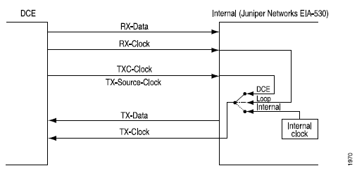
默认情况下,串行接口使用环路时钟模式。对于 EIA-530 和 V.35 接口,您可以单独配置 PIC 上的每个端口,以使用环路、DCE 或内部时钟模式。对于 X.21 接口,仅支持循环时钟模式。
三种时钟模式的工作方式如下:
环路时钟模式 — 使用 DCE 的 RX 时钟将数据从 DCE 时钟传输到 DTE。
DCE 时钟模式 — 使用 TXC 时钟,该时钟由 DCE 生成,专门供 DTE 用作 DTE 的传输时钟。
内部时钟模式 — 也称为线路计时,使用内部生成的时钟。您可以通过在 或
[edit interfaces se-fpc/pic/port dte-options]层次结构级别包含clock-rate[edit interfaces se-pim/0/port serial-options]语句来配置此时钟的速度。有关 DTE 时钟速率的详细信息,请参见 配置 DTE 时钟速率。
请注意,DCE 时钟模式和环路时钟模式使用 DCE 生成的外部时钟。
图 1 显示环路、DCE 和内部时钟模式的时钟源。
要配置串行接口的时钟模式,请包含以下 clocking-mode 语句:
clocking-mode (dce | internal | loop);
您可以在以下层次结构级别包含此语句:
[edit interfaces se-pim/0/port serial-options][edit interfaces se-fpc/pic/port serial-options]
反转串行接口传输时钟
当使用外部定时时钟模式(DCE 或环路)时,长电缆可能会引入 DTE 传输的时钟和数据相移。在高速下,此相移可能会导致错误。反转发射时钟可校正相移,从而降低错误率。
默认情况下,传输时钟不会反转。要反转传输时钟,请包含以下 transmit-clock invert 语句:
transmit-clock invert;
您可以在以下层次结构级别包含此语句:
[edit interfaces se-pim/0/port serial-options][edit interfaces se-fpc/pic/port serial-options]
配置 DTE 时钟速率
默认情况下,串行接口的时钟速率为 16.384 MHz。对于配置了内部时钟模式的EIA-530和V.35接口,您可以配置时钟速率。
要配置时钟速率,请包含以下 clock-rate 语句:
clock-rate rate;
您可以在以下层次结构级别包含此语句:
[edit interfaces se-pim/0/port serial-options][edit interfaces se-fpc/pic/port serial-options]
您可以配置以下接口速度:
2.048兆赫
2.341兆赫
2.731兆赫
3.277兆赫
4.096兆赫
5.461兆赫
8.192兆赫
16.384兆赫
尽管串行接口旨在以默认速率 16.384 MHz 使用,但如果满足以下任一条件,则可能需要使用较慢的速率:
互连电缆太长,无法有效运行。
互连电缆暴露在外来噪声源中,该噪声源可能导致超过+1伏的不需要的电压,该电压在电缆负载端的信号导体和电路之间以差分方式测量,用50欧姆电阻代替发电机。
您需要尽量减少对其他信号的干扰。
您需要反转信号。
有关信令速率与接口电缆距离之间关系的详细信息,请参阅以下标准:
EIA-422-A, 平衡电压数字接口电路的电气特性
EIA-423-A, 不平衡电压数字接口电路的电气特性
配置串行信号处理
默认情况下,为所有信号启用正常信号处理。对于每个信号,该 normal 选项适用于该信号的正常信号处理,如以下标准所定义:
TIA/EIA 标准 530
ITU-T建议书V.35
ITU-T 建议书 X.21
表 4 显示了支持每种信号类型的串行接口模式。
信号 |
串行接口 |
|---|---|
| 来自 DCE 信号 | |
清除发送 (CTS) |
EIA-530 和 V.35 |
数据载波检测 (DCD) |
EIA-530 和 V.35 |
数据集就绪 (DSR) |
EIA-530 和 V.35 |
指示 |
仅限 X.21 |
测试模式 (TM) |
仅限 EIA-530 |
| To-DCE 信号 | |
控制信号 |
仅限 X.21 |
数据传输就绪 (DTR) |
EIA-530 和 V.35 |
发送请求 (RTS) |
EIA-530 和 V.35 |
可以通过包含 dce-options 或 dte-options 语句来配置串行接口信号特性:
dce-options |dte-options {
    control-signal (assert | de-assert | normal);
    cts (ignore | normal | require);
    dcd (ignore | normal | require);
    dsr (ignore | normal | require);
    dtr signal-handling-option;
    ignore-all;
    indication (ignore | normal | require);
    rts (assert | de-assert | normal);
    tm (ignore | normal | require);
}
您可以在以下层次结构级别包含这些语句:
[edit interfaces se-pim/0/port serial-options][edit interfaces se-fpc/pic/port serial-options]
对于 EIA-530 和 V.35 接口,通过包含 dtr 和 rts 语句并指定 assert、 de-assert或 normal 选项来配置 to-DCE 信号:
dtr (assert | de-assert | normal);
rts (assert | de-assert | normal);
对于 X.21 接口,通过包含 control-signal 语句并指定 assert、 de-assert或 normal 选项来配置 to-DCE 信号:
control-signal (assert | de-assert | normal);
断言 是指给定信号的正侧处于潜在的高电平输出电压 (Voh),而同一信号的负侧处于潜在的低电平输出电压 (Vol)。非断言 是指给定信号的正侧处于电位Vol,而同一信号的负侧处于电位Voh。
对于 DTR 信号,您可以使用该信号配置常规信号处理以进行自动重新同步,方法是包含 dtr 语句并指定 auto-synchronize 选项:
dtr {
    auto-synchronize {
        duration milliseconds;
        interval seconds;
    }
}
再同步的脉冲持续时间可以是 1 到 1000 毫秒。重新同步的偏移间隔可以是 1 到 31 秒。
对于 EIA-530 和 V.35 接口,通过包含 cts、 dcd和 dsr 语句并指定 ignore、 normal或 require 选项来配置来自 DCE 信号:
cts (ignore | normal | require);
dcd (ignore | normal | require);
dsr (ignore | normal | require);
对于 X.21 接口,请通过包含 indication 语句、指定 ignore、 normal或 require 选项来配置来自 DCE 信号:
indication (ignore | normal | require);
仅对于 EIA-530 接口,您可以通过包含tm语句并指定 ignore、 或normalrequire选项来配置从 DCE 测试模式 (TM) 信令:
tm (ignore | normal | require);
要指定必须置位来自 DCE 信号,请在配置中包含该 require 选项。要指定必须忽略来自 DCE 信号,请在配置中包含该 ignore 选项。
对于 V.35 和 X.21 接口,不能在配置中包含该 tm 语句。
对于 X.21 接口,不能cts在配置中包含 、 dcd、 dsrdtr和 rts 语句。
对于 EIA-530 和 V.35 接口,不能 control-signal 在配置中包含 and indication 语句。
有关每种串行接口模式不支持的串行选项语句的完整列表,请参阅 无效的串行接口语句。
要返回到默认的正常信号处理,请从配置中删除 require、 ignore、 assert或de-assertauto-synchronize语句,如以下示例所示:
[edit]
user@host# delete interfaces se-fpc/pic/port dte-options control-leads cts require
要显式配置常规信号处理,请将语句包含在 control-signal 选项中 normal :
control-signal normal;
您可以通过包含 ignore-all 以下语句将串行接口配置为忽略所有控制引线:
ignore-all;
仅当未在 或 [edit interfaces se-fpc/pic/port serial-options dte-options] 层次结构级别显式[edit interfaces se-pim/0/port serial-options dce-options]启用其他信号处理选项时,才能ignore-all在配置中包含该语句。
您可以在以下层次结构级别包含 control-signal、 cts、 dsrindicationrtsdcddtr和 tm 语句:
[edit interfaces se-pim/0/port serial-options dte-options][edit interfaces se-fpc/pic/port serial-options dte-options]
配置串行 DTR 电路
平衡电路具有两个幅度相等且相位相反的电流。不平衡电路有一个电流和一个接地;如果一对端子不平衡,则一侧连接到电气接地,另一侧传输信号。默认情况下,DTR 电路是平衡的。
对于 EIA-530 和 V.35 接口,请通过包含 dtr-circuit 以下语句来配置 DTR 电路:
dtr-circuit (balanced | unbalanced);
您可以在以下层次结构级别包含此语句:
[edit interfaces se-pim/0/port serial-options][edit interfaces se-fpc/pic/port serial-options]
配置串行信号极性
串行接口使用差分协议信令技术。在与电路相关的两个串行信号中,称为A信号的信号用加号表示,称为B信号的信号用减号表示;例如,DTR+ 和 DTR–。如果 DTR 较低,则 DTR+ 相对于 DTR– 为负值。如果DTR较高,则DTR+相对于DTR-为正。
默认情况下,所有信号极性均为正。您可以在瞻博网络串行接口上反转此极性。如果信号由于反极性而接线错误,则可能需要执行此操作。
对于 EIA-530 和 V.35 接口,通过添加 cts-polarity、 dcd-polarity、 rts-polaritydsr-polaritydtr-polarity、 和tm-polarity语句来配置信号极性:
cts-polarity (negative | positive);
dcd-polarity (negative | positive);
dsr-polarity (negative | positive);
dtr-polarity (negative | positive);
rts-polarity (negative | positive);
tm-polarity (negative | positive);
您可以在以下层次结构级别包含这些语句:
[edit interfaces se-pim/0/port serial-options][edit interfaces se-fpc/pic/port serial-options]
对于 X.21 接口,通过包含 control-polarity and indication-polarity 语句来配置信号极性:
control-polarity (negative | positive);
indication-polarity (negative | positive);
您可以在以下层次结构级别包含这些语句:
[edit interfaces se-pim/0/port serial-options][edit interfaces se-fpc/pic/port serial-options]
配置串行环回功能
从路由器,远程线路接口单元 (LIU) 环路将 TX(发送)数据和 TX 时钟作为 RX(接收)数据和 RX 时钟环回路由器。从线路中,LIU 环回将 RX 数据和 RX 时钟循环回线路,作为 TX 数据和 TX 时钟,如 所示 图 2。
DCE 本地和 DCE 远程控制 EIA-530 接口特定信号,用于在链路伙伴 DCE 上启用本地和远程环回。本地环回如 所示 图 3。
对于 EIA-530 接口,您可以配置 DCE 本地、DCE 远程、本地和远程 (LIU) 环路功能。
对于 V.35,您可以配置远程 LIU 和本地环路功能。V.35 和 X.21 接口不支持 DCE 本地和 DCE 远程环路。X.21 接口不支持本地和远程环路。
要在串行接口上配置环路功能,请包含语句, loopback 并指定 dce-local、 dce-remote、 local或 remote 选项:
loopback mode;
您可以在以下层次结构级别包含此语句:
[edit interfaces se-pim/0/port serial-options][edit interfaces se-fpc/pic/port serial-options]
要禁用环回功能,请从配置中删除语句 loopback :
[edit]
user@host# delete interfaces se-fpc/pic/port serial-options loopback
您可以通过检查命令输出 show interface se-fpc/pic/port extensive 中的错误计数器来确定是否存在内部或外部问题:
user@host> show interfaces se-fpc/pic/port extensive
要配置串行环回功能:
配置串行线路编码
默认情况下,串行接口使用不归零 (NRZ) 线路编码。如有必要,可以配置不归零反转 (NRZI) 行编码。
要使接口使用 NRZI 行编码,请包含 encoding 语句,并指定 nrzi 选项:
encoding nrzi;
要显式配置默认 NRZ 线路编码,请包含 encoding 语句,并指定 nrz 选项:
encoding nrz;
您可以在以下层次结构级别包含此语句:
[edit interfaces se-pim/0/port serial-options][edit interfaces se-fpc/pic/port serial-options]
设置线路编码参数时,必须为配对端口设置相同的值。端口 0 和 1 必须共享相同的值。
在 SRX 设备上配置串行接口
在此示例中,您将了解如何在串行接口上完成初始配置、如何删除串行接口以及如何配置串行接口 8 端口同步串行 GPIM。
有关在 SRX 系列防火墙中安装串行 PIM 的信息,请参阅 分支物理接口模块硬件指南的 SRX 系列防火墙。
在此示例中:
在串行接口上创建新接口 .
se-1/0/0将封装类型设置为 ppp,并为 创建
se-1/0/0基本配置。将逻辑接口设置为 0,逻辑单元号的范围为 0 到 16,384。
输入需要在逻辑接口上配置的属性的其他值,例如逻辑封装或协议族。
将 IPv4 地址 10.10.10.10/24 设置为
se-1/0/0。
删除 se-1/0/0 接口时,该接口将被禁用并从软件配置中删除。网络接口物理上仍然存在,其标识符继续显示在 J-Web 页面上。
基本串行接口配置
在此示例中,您将创建一个名为 se-1/0/0 的串行接口,并将封装类型设置为 ppp。要快速配置此示例,请在层次结构级别使用 [edit] CLI 快速配置,然后从配置模式提交。
set interfaces se-1/0/0 encapsulation ppp unit 0 family inet address 10.10.10.10/24
要配置串行接口, se-1/0/0请执行以下操作:
成功完成配置后,使用命令查看 show interfaces se-1/0/0 参数。
删除串行接口
在此示例中,您将删除串行接口 se-1/0/0。配置接口之前,不需要进行设备初始化以外的任何配置。
要删除串行接口, se-1/0/0请执行以下操作:
成功完成配置后,要使用命令验证 show interfaces 配置。
示例:在 8 端口同步串行 GPIM 上配置串行接口
在此示例中,您可以使用 8 端口同步串行 GPIM 执行基本的背对背设备配置。这些设备显示为数据通信设备(DCE)和数据终端设备(DTE)。在某些部署方案中,DTE 可以是串行调制解调器、加密器或解密器。
在此方案中,您可以使用两个接口配置串行接口。您可以使用不同的封装配置所有端口,例如思科高级数据链路控制 (HDLC)、帧中继和点对点协议 (PPP)。设置帧中继后,还必须设置数据链路连接标识符(在本例中为 111)。设备 1 (SRX650) 上的所有 8 个端口均配置为 DTE 模式,设备 2 (SRX650) 上各自的 8 个端口配置为 DCE 模式。
在此示例中,对于设备 1:
将封装类型设置为
ppp,将逻辑接口0设置为 。逻辑单元号的范围为 0 到 16,384。输入需要在逻辑接口上配置的属性的其他值,例如逻辑封装或协议族。
在串行端口上将 IPv4 地址设置为 10.10.10.1/24。
对于设备 2,遵循与设备 1 类似的过程,但将时钟模式设置为 dce。
图 4 显示了此示例中使用的拓扑。
要快速配置此示例,请在层次结构级别使用 [edit] CLI:
设备 1
set interfaces se-7/0/0 mtu 9192set interfaces se-7/0/0 encapsulation pppset interfaces se-7/0/0 serial-options clocking-mode internalset interfaces se-7/0/0 unit 0 family inet address 10.10.10.1/24set interfaces se-7/0/1 mtu 9192set interfaces se-7/0/1 encapsulation cisco-hdlcset interfaces se-7/0/1 serial-options clocking-mode internalset interfaces se-7/0/1 unit 0 family inet address 11.11.11.1/24set interfaces se-7/0/2 dceset interfaces se-7/0/2 mtu 9192set interfaces se-7/0/2 encapsulation frame-relayset interfaces se-7/0/2 serial-options clocking-mode internalset interfaces se-7/0/2 unit 0 dlci 111set interfaces se-7/0/2 unit 0 family inet address 12.12.12.1/24set interfaces se-7/0/3 mtu 9192set interfaces se-7/0/3 encapsulation pppset interfaces se-7/0/3 serial-options clocking-mode internalset interfaces se-7/0/3 unit 0 family inet address 13.13.13.1/24set interfaces se-7/0/4 mtu 9192set interfaces se-7/0/4 encapsulation cisco-hdlcset interfaces se-7/0/4 serial-options clocking-mode internalset interfaces se-7/0/4 unit 0 family inet address 14.14.14.1/24set interfaces se-7/0/5 dceset interfaces se-7/0/5 mtu 9192set interfaces se-7/0/5 encapsulation frame-relayset interfaces se-7/0/5 serial-options clocking-mode internalset interfaces se-7/0/5 unit 0 dlci 112set interfaces se-7/0/5 unit 0 family inet address 15.15.15.1/24set interfaces se-7/0/6 mtu 9192set interfaces se-7/0/6 encapsulation cisco-hdlcset interfaces se-7/0/6 serial-options clocking-mode internalset interfaces se-7/0/6 unit 0 family inet address 16.16.16.1/24set interfaces se-7/0/7 mtu 9192set interfaces se-7/0/7 encapsulation pppset interfaces se-7/0/7 serial-options clocking-mode internalset interfaces se-7/0/7 unit 0 family inet address 17.17.17.1/24set routing-options static route 21.21.21.0/24 next-hop 10.10.10.2set routing-options static route 23.23.23.0/24 next-hop 11.11.11.2set routing-options static route 25.25.25.0/24 next-hop 12.12.12.2set routing-options static route 27.27.27.0/24 next-hop 13.13.13.2set routing-options static route 29.29.29.0/24 next-hop 14.14.14.2set routing-options static route 31.31.31.0/24 next-hop 15.15.15.2set routing-options static route 33.33.33.0/24 next-hop 16.16.16.2set routing-options static route 35.35.35.0/24 next-hop 17.17.17.2
设备 2
set interfaces se-3/0/0 mtu 9192set interfaces se-3/0/0 encapsulation pppset interfaces se-3/0/0 serial-options clocking-mode dceset interfaces se-3/0/0 unit 0 family inet address 10.10.10.2/24set interfaces se-3/0/1 mtu 9192set interfaces se-3/0/1 encapsulation cisco-hdlcset interfaces se-3/0/1 serial-options clocking-mode dceset interfaces se-3/0/1 unit 0 family inet address 11.11.11.2/24set interfaces se-3/0/2 dceset interfaces se-3/0/2 mtu 9192set interfaces se-3/0/2 encapsulation frame-relayset interfaces se-3/0/2 serial-options clocking-mode dceset interfaces se-3/0/2 unit 0 dlci 111set interfaces se-3/0/2 unit 0 family inet address 12.12.12.2/24set interfaces se-3/0/3 mtu 9192set interfaces se-3/0/3 encapsulation pppset interfaces se-3/0/3 serial-options clocking-mode dceset interfaces se-3/0/3 unit 0 family inet address 13.13.13.2/24set interfaces se-3/0/4 mtu 9192set interfaces se-3/0/4 encapsulation cisco-hdlcset interfaces se-3/0/4 serial-options clocking-mode dceset interfaces se-3/0/4 unit 0 family inet address 14.14.14.2/24set interfaces se-3/0/5 dceset interfaces se-3/0/5 mtu 9192set interfaces se-3/0/5 encapsulation frame-relayset interfaces se-3/0/5 serial-options clocking-mode dceset interfaces se-3/0/5 unit 0 dlci 112set interfaces se-3/0/5 unit 0 family inet address 15.15.15.2/24set interfaces se-3/0/6 mtu 9192set interfaces se-3/0/6 encapsulation cisco-hdlcset interfaces se-3/0/6 serial-options clocking-mode dceset interfaces se-3/0/6 unit 0 family inet address 16.16.16.2/24set interfaces se-3/0/7 mtu 9192set interfaces se-3/0/7 encapsulation pppset interfaces se-3/0/7 serial-options clocking-mode dceset interfaces se-3/0/7 unit 0 family inet address 17.17.17.2/24set routing-options static route 20.20.20.0/24 next-hop 10.10.10.1set routing-options static route 22.22.22.0/24 next-hop 11.11.11.1set routing-options static route 24.24.24.0/24 next-hop 12.12.12.1set routing-options static route 26.26.26.0/24 next-hop 13.13.13.1set routing-options static route 28.28.28.0/24 next-hop 14.14.14.1set routing-options static route 30.30.30.0/24 next-hop 15.15.15.1set routing-options static route 32.32.32.0/24 next-hop 16.16.16.1set routing-options static route 34.34.34.0/24 next-hop 17.17.17.1
要在设备 1 上配置接口,请执行以下操作:
要在设备 2 上配置接口,请执行以下操作:
指定接口的 MTU 值。
[edit interfaces] user@host#
set se-3/0/0 mtu 9192设置封装类型。
[edit interfaces] user@host#
set se-3/0/0 encapsulation ppp设置串行选项,例如时钟模式。
[edit interfaces] user@host#
set se-3/0/0 serial-options clocking-mode dce设置串行端口上的 IPv4 地址。
[edit interfaces] user@host#
set se-3/0/0 unit 0 family inet address 10.10.10.2/24指定静态路由信息。
[edit routing-options] user@host#
set static route 20.20.20.0/24 next-hop 10.10.10.1对设备 2 上的其他七个端口重复相同的配置。
配置完设备后,提交配置。
[edit]
user@host# commit
验证
目的
显示有关串行接口上配置的参数的信息。
操作
您可以在网络中的每个对等地址上使用 ping 工具来验证设备上的所有接口是否正常运行。要验证所有接口的链路状态,请执行以下操作:
对于设备上的每个接口:
在 J-Web 界面中,选择
Troubleshoot > Ping Host。在“远程主机”框中,键入要验证其链路状态的接口的地址。
单击
Start。输出显示在单独的页面上。
PING 10.10.10.10 : 56 data bytes
64 bytes from 10.10.10.10: icmp_seq=0 ttl=255 time=0.382 ms
64 bytes from 10.10.10.10: icmp_seq=1 ttl=255 time=0.266 ms
如果接口正常运行,则会生成 ICMP 响应。如果收到此响应,则时间字段中将列出往返时间(以毫秒为单位)。
要验证接口属性是否正确,
show interfaces detail请使用命令显示接口信息摘要。验证以下信息:物理接口已启用。如果接口显示为“已禁用”,请执行以下操作之一:
在 CLI 配置编辑器中,删除
disable配置层次结构的 [编辑接口 se-1/0/0] 级别的语句。在 J-Web 配置编辑器中,清除接口> se-1/0/0 页面上的
Disable复选框。
物理链路已启动。链路状态为“关闭”表示接口模块、接口端口或物理连接存在问题(链路层错误)。
“上次翻动时间”是预期值。它指示物理接口上次变为不可用然后再次可用的时间。意外抖动表示可能存在链路层错误。
流量统计信息反映预期的输入和输出速率。验证入站和出站字节和数据包的数量是否与物理接口的预期吞吐量相匹配。若要清除统计信息并仅查看新更改,请使用
clear interfaces statistics se-1/0/0命令。
要验证接口链路状态是否为 up,请使用 enter 以下命令:
show interface terse se-7/0/*user@srx650-1>
show interface terse se-7/0/*Interface Admin Link Proto Local Remote se-7/0/0 up up se-7/0/0.0 up up inet 10.10.10.1/24 se-7/0/1 up up se-7/0/1.0 up up inet 11.11.11.1/24 se-7/0/2 up up se-7/0/2.0 up up inet 12.12.12.1/24 se-7/0/3 up up se-7/0/3.0 up up inet 13.13.13.1/24 se-7/0/4 up up se-7/0/4.0 up up inet 14.14.14.1/24 se-7/0/5 up up se-7/0/5.0 up up inet 15.15.15.1/24 se-7/0/6 up up se-7/0/6.0 up up inet 16.16.16.1/24 se-7/0/7 up up se-7/0/7.0 up up inet 17.17.17.1/24
输出显示已配置的所有接口的列表。如果显示
up所有接口的“链接”列,则配置正确。这将验证 GPIM 是否启动以及端到端 ping 是否正常工作。要验证 DCE 的接口统计信息,请使用
show interface se-7/0/0 extensive | no-more以下命令:user@srx650-1>
show interface se-7/0/0 extensive | no-morePhysical interface: se-7/0/0, Enabled, Physical link is Up Interface index: 161, SNMP ifIndex: 592, Generation: 164 Type: Serial, Link-level type: PPP, MTU: 1504, Maximum speed: 8mbps Device flags : Present Running Interface flags: Point-To-Point Internal: 0x0 Link flags : Keepalives Hold-times : Up 0 ms, Down 0 ms Keepalive settings: Interval 10 seconds, Up-count 1, Down-count 3 Keepalive statistics: Input : 123 (last seen 00:00:02 ago) Output: 123 (last sent 00:00:01 ago) LCP state: Opened NCP state: inet: Opened, inet6: Not-configured, iso: Not-configured, mpls: Not-configured CHAP state: Closed PAP state: Closed CoS queues : 8 supported, 8 maximum usable queues Last flapped : 2011-06-27 22:57:24 PDT (00:20:59 ago) Statistics last cleared: Never Traffic statistics: Input bytes : 23792 160 bps Output bytes : 22992 536 bps Input packets: 404 0 pps Output packets: 409 0 pps Input errors: Errors: 3, Drops: 0, Framing errors: 3, Runts: 0, Giants: 0, Policed discards: 0, Resource errors: 0 Output errors: Carrier transitions: 1, Errors: 0, Drops: 0, MTU errors: 0, Resource errors: 0 Egress queues: 8 supported, 4 in use Queue counters: Queued packets Transmitted packets Dropped packets 0 best-effort 0 0 0 1 expedited-fo 0 0 0 2 assured-forw 0 0 0 3 network-cont 409 409 0 Queue number: Mapped forwarding classes 0 best-effort 1 expedited-forwarding 2 assured-forwarding 3 network-control Serial media information: Line protocol: eia530 Resync history: Sync loss count: 0 Data signal: Rx Clock: OK Control signals: Local mode: DCE To DTE: CTS: up, DCD: up, DSR: up From DTE: DTR: up, RTS: up DCE loopback override: Off Clocking mode: internal Loopback: none Tx clock: non-invert Line encoding: nrz Packet Forwarding Engine configuration: Destination slot: 7 CoS information: Direction : Output CoS transmit queue Bandwidth Buffer Priority Limit % bps % usec 0 best-effort 95 7600000 95 0 low none 3 network-control 5 400000 5 0 low none continue................................................................................ ..........................................................................................输出显示所有 DCE 验证参数和配置模式的列表。如果本地模式显示 DCE,则配置正确。
要验证 DTE 的接口统计信息,请使用
show interface se-3/0/0 extensive | no-more以下命令:user@srx650-2>
show interfaces se-3/0/0 extensive | no-morePhysical interface: se-3/0/0, Enabled, Physical link is Up Interface index: 168, SNMP ifIndex: 594, Generation: 171 Type: Serial, Link-level type: PPP, MTU: 1504, Maximum speed: 8mbps Device flags : Present Running Interface flags: Point-To-Point Internal: 0x0 Link flags : Keepalives Hold-times : Up 0 ms, Down 0 ms Keepalive settings: Interval 10 seconds, Up-count 1, Down-count 3 Keepalive statistics: Input : 242 (last seen 00:00:09 ago) Output: 242 (last sent 00:00:10 ago) LCP state: Opened NCP state: inet: Opened, inet6: Not-configured, iso: Not-configured, mpls: Not-configured CHAP state: Closed PAP state: Closed CoS queues : 8 supported, 8 maximum usable queues Last flapped : 2011-06-27 22:52:06 PDT (00:40:41 ago) Statistics last cleared: Never Traffic statistics: Input bytes : 44582 0 bps Output bytes : 42872 0 bps Input packets: 776 0 pps Output packets: 779 0 pps Input errors: Errors: 6, Drops: 0, Framing errors: 6, Runts: 0, Giants: 0, Policed discards: 0, Resource errors: 0 Output errors: Carrier transitions: 1, Errors: 0, Drops: 0, MTU errors: 0, Resource errors: 0 Egress queues: 8 supported, 4 in use Queue counters: Queued packets Transmitted packets Dropped packets 0 best-effort 2 2 0 1 expedited-fo 0 0 0 2 assured-forw 0 0 0 3 network-cont 777 777 0 Queue number: Mapped forwarding classes 0 best-effort 1 expedited-forwarding 2 assured-forwarding 3 network-control Serial media information: Line protocol: eia530 Resync history: Sync loss count: 0 Data signal: Rx Clock: OK Control signals: Local mode: DTE To DCE: DTR: up, RTS: up From DCE: CTS: up, DCD: up, DSR: up Clocking mode: loop-timed Loopback: none Tx clock: non-invert Line encoding: nrz Packet Forwarding Engine configuration: Destination slot: 3 CoS information: Direction : Output CoS transmit queue Bandwidth Buffer Priority Limit % bps % usec 0 best-effort 95 7600000 95 0 low none 3 network-control 5 400000 5 0 low none continue ........................................................................... .....................................................................................输出显示所有 DTE 验证参数和配置模式的列表。如果本地模式显示 DTE,则配置正确。