
本页内容
示例:在使用 EVPN-MPLS 多宿主的逻辑接口上配置 ESI
当以太网 VPN MPLS (EVPN-MPLS) 环境中的客户边缘 (客户边缘) 设备多宿主到两个或多个提供商边缘 (PE) 设备时,连接这些设备的以太网链路集将构成一个以太网段。以太网段标识符 (ESI) 是一个 10 个八位位组的整数,用于标识此段。示例 ESI 为 00:11:22:33:44:55:66:77:88:99。
在 MX 系列路由器的 Junos OS 15.1F6 和 16.1R4 之前的版本以及 EX9200 交换机的 Junos OS 17.3R1 之前的版本中,只能在物理或聚合以太网接口上指定 ESI,例如 set interfaces ae0 esi 00:11:22:33:44:55:66:77:88:99。如果您在物理或聚合以太网接口上指定 ESI,请记住,ESI 是指定转发器 (DF) 选择过程中的一个因素。例如,假设您在聚合以太网接口 ae0 上配置 EVPN 多宿主主动-备用,并且给定在 ae0 上配置的 ESI 和其他决定因素,DF 选择将导致 ae0 处于关闭状态。此外,例如, set interfaces ae0 unit 1 set interfaces ae0 unit 2 在 ae0 上配置的所有逻辑接口也处于关闭状态,这将导致逻辑接口 ae0.1 和 ae0.2 无法向各自的客户站点 (VLAN) 提供服务。
您可以在逻辑接口上指定 ESI。如果在逻辑接口上指定 ESI,则 DF 选择过程现在发生在单个逻辑接口级别,这使您能够更好地利用逻辑接口。例如,假设在聚合以太网接口 ae0 上配置逻辑接口 ae0.1 和 ae0.2。您在两个逻辑接口上均配置 EVPN 多宿主主动-备用,并且给定在 ae0.1 上配置的 ESI 和其他决定因素,DF 选择将导致 ae0.1 处于关闭状态。尽管逻辑接口 ae0.1 已关闭,但逻辑接口 ae0.2 和在 ae0 上配置的其他逻辑接口仍可处于运行状态,并向各自的客户站点 (VLAN) 提供服务。
本主题介绍如何在 EVPN 多宿主主动-备用和主动-主动模式下的逻辑接口上配置 ESI。
要求
EVPN 多宿主主动-备用和多宿主主动-主动示例都使用以下硬件和软件组件:
-
运行 Junos OS 17.3R1 或更高版本 (PE1) 的 EX9200 交换机
-
运行 Junos OS 15.1F6 或更高版本或 Junos OS 17.1R1 或更高版本 (PE2) 的 MX 系列路由器
概述和拓扑
EVPN Multihoming Active-Standby
图 1 显示了一种 EVPN-MPLS 拓扑,其中 CE1 与 PE1 和 PE2 多宿主,以便为 CE2 提供冗余路径。在 CE1 上,与 PE1 和 PE2 的连接配置为单独的聚合以太网接口。 表 1 显示了如何在 PE1 和 PE2 上配置与 CE1 的连接。请注意,EVPN 多宿主模式、ESI 和 VLAN ID 实际上配置在每个 PE 设备上的逻辑接口 ae0.1 上。
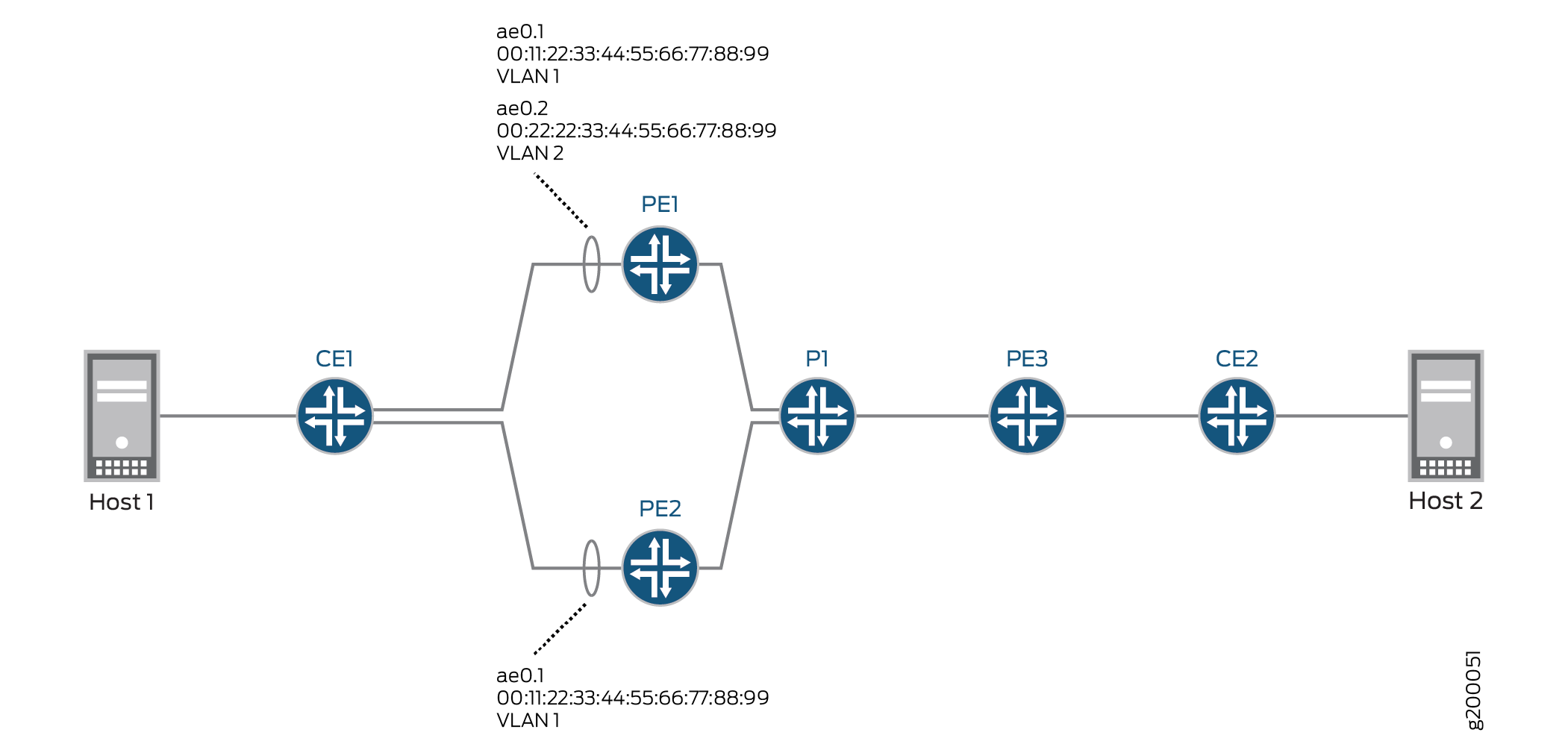 功能的 EVPN-MPLS 拓扑
|
设备 |
物理接口 |
聚合以太网接口 |
逻辑接口 |
EVPN 多宿主模式 |
ESI |
VLAN ID |
|---|---|---|---|---|---|---|
|
PE1 |
xe-2/0/0 |
ae0 |
ae0.1 |
单活动 |
00:11:22:33:44:55:66:77:88:99 |
1 |
|
PE2 |
xe-3/0/2 |
ae0 |
ae0.1 |
单活动 |
00:11:22:33:44:55:66:77:88:99 |
1 |
根据 DF 选择,PE2 上的逻辑接口 ae0.1 处于运行状态,PE1 上的逻辑接口 ae0.1 处于关闭状态。
表 2 还显示了 PE1 上逻辑接口 ae0.2 的配置。请注意,逻辑接口 ae0.2 为不同的 VLAN 提供服务,并且配置的 ESI 与逻辑接口 ae0.1 不同,后者配置在同一聚合以太网接口上。因此,尽管逻辑接口 ae0.1 处于关闭状态,但逻辑接口 ae0.2 仍处于开启状态并向 VLAN 2 提供服务。
|
设备 |
物理接口 |
聚合以太网接口 |
逻辑接口 |
EVPN 多宿主模式 |
ESI |
VLAN ID |
|---|---|---|---|---|---|---|
|
PE1 |
xe-2/0/0 |
ae0 |
ae0.2 |
单活动 |
00:22:22:33:44:55:66:77:88:99 |
2 |
EVPN Multihoming Active-Active
图 2 显示了 EVPN-MPLS 拓扑,其中 CE1 与 PE1 和 PE2 多宿主,以便为 CE2 提供冗余路径。在 CE1 上,与 PE1 和 PE2 的连接配置为一个聚合以太网接口。 表 3 显示了如何在 PE1 和 PE2 上配置与 CE1 的连接。请注意,EVPN 多宿主模式、ESI 和 VLAN ID 实际上是在每台设备上的逻辑接口 ae0.1 上配置的。
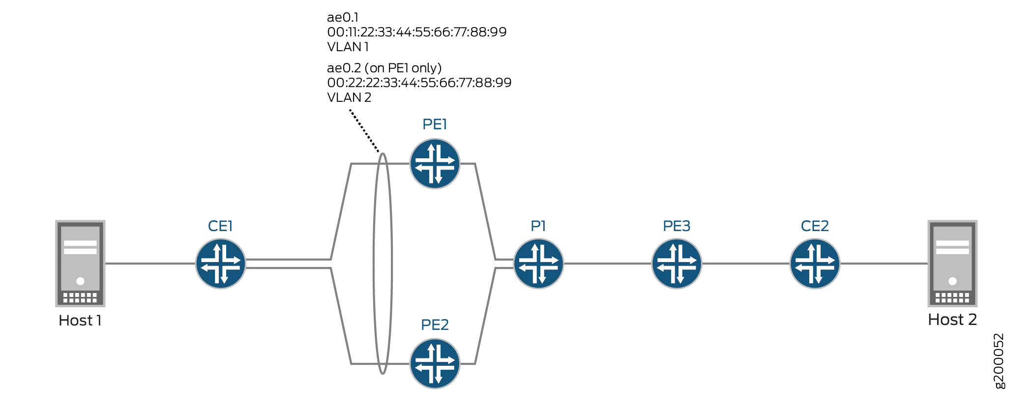 EVPN-MPLS 拓扑
|
设备 |
物理接口 |
聚合以太网接口 |
逻辑接口 |
EVPN 多宿主模式 |
ESI |
VLAN ID |
|---|---|---|---|---|---|---|
|
PE1 |
xe-2/0/0 |
ae0 |
ae0.1 |
全活动 |
00:11:22:33:44:55:66:77:88:99 |
1 |
|
PE2 |
xe-3/0/2 |
ae0 |
ae0.1 |
全活动 |
00:11:22:33:44:55:66:77:88:99 |
1 |
根据 DF 选择,PE1 上的逻辑接口 ae0.1 处于运行状态,PE2 上的逻辑接口 ae0.1 处于关闭状态。
表 4 还显示了 PE1 上逻辑接口 ae0.2 的配置。请注意,逻辑接口 ae0.2 为不同的 VLAN 提供服务,并且配置的 ESI 与逻辑接口 ae0.1 不同,后者位于同一聚合以太网接口中。结果,逻辑接口 ae0.2 已关闭,无法向 VLAN 2 提供服务,尽管逻辑接口 ae0.1 处于运行状态。
|
设备 |
物理接口 |
聚合以太网接口 |
逻辑接口 |
EVPN 多宿主模式 |
ESI |
VLAN ID |
|---|---|---|---|---|---|---|
|
PE1 |
xe-2/0/0 |
ae0 |
ae0.2 |
全活动 |
00:22:22:33:44:55:66:77:88:99 |
2 |
EVPN 多宿主主动-备用配置
PE1 (EX9200) 和 PE2(MX 系列路由器)的配置侧重于在逻辑接口上配置 EVPN 多宿主、主动-备用和 ESI。这些配置不包括物理接口、聚合以太网接口、逻辑接口和路由实例的所有 EVPN 相关配置。有关在 EVPN-MPLS 环境中 EVPN 多宿主主动-备用的更全面配置,请参阅 示例:配置基本 EVPN-MPLS 主动-备用多宿主。
CLI 快速配置
PE1
set interfaces xe-2/0/0 gigether-options 802.3ad ae0
set interfaces ae0 flexible-vlan-tagging
set interfaces ae0 encapsulation flexible-ethernet-services
set interfaces ae0 unit 1 encapsulation vlan-bridge
set interfaces ae0 unit 1 vlan-id 1
set interfaces ae0 unit 1 esi 00:11:22:33:44:55:66:77:88:99
set interfaces ae0 unit 1 esi single-active
set interfaces ae0 unit 2 encapsulation vlan-bridge
set interfaces ae0 unit 2 vlan-id 2
set interfaces ae0 unit 2 esi 00:22:22:33:44:55:66:77:88:99
set interfaces ae0 unit 2 esi single-active
set interfaces irb unit 1 family inet address 192.0.2.1/24
set interfaces irb unit 2 family inet address 192.0.2.2/24
set routing-instances blue instance-type evpn
set routing-instances blue vlan-id 1
set routing-instances blue interface ae0.1
set routing-instances blue l3-interface irb.1
...
set routing-instances blue protocols evpn interface ae0.1
set routing-instances green instance-type evpn
set routing-instances green vlan-id 2
set routing-instances green interface ae0.2
set routing-instances green l3-interface irb.2
...
set routing-instances green protocols evpn interface ae0.2
set routing-instances vrf instance-type vrf
set routing-instances vrf interface irb.1
set routing-instances vrf interface irb.2
...
PE2
set interfaces xe-3/0/2 gigether-options 802.3ad ae0
set interfaces ae0 flexible-vlan-tagging
set interfaces ae0 encapsulation flexible-ethernet-services
set interfaces ae0 unit 1 encapsulation vlan-bridge
set interfaces ae0 unit 1 vlan-id 1
set interfaces ae0 unit 1 esi 00:11:22:33:44:55:66:77:88:99
set interfaces ae0 unit 1 esi single-active
set interfaces irb unit 1 family inet address 192.0.2.1/24
set routing-instances blue instance-type evpn
set routing-instances blue vlan-id 1
set routing-instances blue interface ae0.1
set routing-instances blue routing-interface irb.1
...
set routing-instances blue protocols evpn interface ae0.1
set routing-instances vrf instance-type vrf
set routing-instances vrf interface irb.1
...
过程
分步程序
要在 PE1 上配置 EVPN 多宿主主动-备用:
-
将以太网接口指定为聚合以太网接口 ae0 的成员。
[edit interfaces]
user@switch# set xe-2/0/0 gigether-options 802.3ad ae0
-
将聚合以太网接口 ae0 配置为同时传输 802.1Q VLAN 单标记和双标记帧,并在逻辑接口级别支持不同类型的以太网封装。
[edit interfaces]
user@switch# set ae0 flexible-vlan-tagging
user@switch# set ae0 encapsulation flexible-ethernet-services
-
在聚合以太网接口 ae0 上,配置逻辑接口 ae0.1 和 ae0.2。将逻辑接口配置为使用 VLAN 网桥封装,并将逻辑接口分别映射到 VLAN 1 和 2。此外,将 ESI 分配给逻辑接口,并启用 EVPN 多宿主主动-备用。
[edit interfaces]
user@switch# set ae0 unit 1 encapsulation vlan-bridge
user@switch# set ae0 unit 1 vlan-id 1
user@switch# set ae0 unit 1 esi 00:11:22:33:44:55:66:77:88:99
user@switch# set ae0 unit 1 esi single-active
user@switch# set ae0 unit 2 encapsulation vlan-bridge
user@switch# set ae0 unit 2 vlan-id 2
user@switch# set ae0 unit 2 esi 00:22:22:33:44:55:66:77:88:99
user@switch# set ae0 unit 2 esi single-active
-
配置 IRB 接口 IRB.1 和 IRB.2,并为每个接口分配一个 IP 地址。
[edit interfaces] set interfaces irb unit 1 family inet address 192.0.2.1/24 set interfaces irb unit 2 family inet address 192.0.2.2/24 -
配置名为 blue 的 EVPN 路由实例。将路由实例映射到 VLAN 1、逻辑接口 ae0.1 和 IRB 接口 irb.1。为 EVPN 路由实例配置 EVPN 逻辑接口 ae0.1。
[edit routing-instances]
user@switch# set blue instance-type evpn
user@switch# set blue vlan-id 1
user@switch# set blue interface ae0.1
user@switch# set blue l3-interface irb.1
user@switch# set blue protocols evpn interface ae0.1
-
配置名为 green 的 EVPN 路由实例。将路由实例映射到 VLAN 2、逻辑接口 ae0.2 和 IRB 接口 irb.2。为 EVPN 路由实例配置逻辑接口 ae0.2。
[edit routing-instances]
user@switch# set green instance-type evpn
user@switch# set green vlan-id 2
user@switch# set green interface ae0.2
user@switch# set green l3-interface irb.2
user@switch# set green protocols evpn interface ae0.2
-
配置 VRF 路由实例,并将 IRB 接口 IRB.1 和 IRB.2 添加到路由实例。
[edit routing-instances]
set vrf instance-type vrf


                        set vrf interface irb.1


                        set vrf interface irb.2
分步程序
要在 PE2 上配置 EVPN 多宿主主动-备用:
-
将以太网接口指定为聚合以太网接口 ae0 的成员。
[edit interfaces]
user@router# set xe-3/0/2 gigether-options 802.3ad ae0
-
将聚合以太网接口 ae0 配置为同时传输 802.1Q VLAN 单标记和双标记帧,并在逻辑接口级别支持不同类型的以太网封装。
[edit interfaces]
user@router# set ae0 flexible-vlan-tagging
user@router# set ae0 encapsulation flexible-ethernet-services
-
在聚合以太网接口 ae0 上,配置逻辑接口 ae0.1。将逻辑接口配置为使用 VLAN 网桥封装,并将逻辑接口映射到 VLAN 1 和 2。此外,将 ESI 分配给逻辑接口,并启用 EVPN 多宿主主动-备用。
[edit interfaces]
user@router# set ae0 unit 1 encapsulation vlan-bridge
user@router# set ae0 unit 1 vlan-id 1
user@router# set ae0 unit 1 esi 00:11:22:33:44:55:66:77:88:99
user@router# set ae0 unit 1 esi single-active
-
配置 IRB 接口 IRB.1,并为接口分配 IP 地址。
[edit interfaces]
user@router# set irb unit 1 family inet address 192.0.2.1/24
-
配置名为 blue 的 EVPN 路由实例。将路由实例映射到 VLAN 1、逻辑接口 ae0.1 和 IRB 接口 irb.1。为 EVPN 路由实例配置 EVPN 逻辑接口 ae0.1。
[edit routing-instances]
user@router# set blue instance-type evpn
user@router# set blue vlan-id 1
user@router# set blue interface ae0.1
user@router# set blue routing-interface irb.1
user@router# set blue protocols evpn interface ae0.1
-
配置 VRF 路由实例,并将 IRB 接口 IRB.1 添加到路由实例。
[edit routing-instances]
user@router# set vrf instance-type vrf
user@router# set vrf interface irb.1
EVPN 多宿主主动-主动配置
CLI 快速配置
PE1 (EX9200) 和 PE2(MX 系列路由器)的配置侧重于在逻辑接口上配置 EVPN 多宿主、主动-主动和 ESI。这些配置不包括物理接口、聚合以太网接口、逻辑接口和路由实例的所有 EVPN 相关配置。有关 EVPN 多宿主主动-主动的更全面配置,请参阅 示例:配置 EVPN 主动-主动多宿主。请注意,参考示例说明了如何在物理和聚合以太网接口上配置 ESI。
PE1
set interfaces xe-2/0/0 gigether-options 802.3ad ae0
set interfaces ae0 flexible-vlan-tagging
set interfaces ae0 encapsulation flexible-ethernet-services
set interfaces ae0 unit 1 encapsulation vlan-bridge
set interfaces ae0 unit 1 vlan-id 1
set interfaces ae0 unit 1 esi 00:11:22:33:44:55:66:77:88:99
set interfaces ae0 unit 1 esi all-active
set interfaces ae0 unit 2 encapsulation vlan-bridge
set interfaces ae0 unit 2 vlan-id 2
set interfaces ae0 unit 2 esi 00:22:22:33:44:55:66:77:88:99
set interfaces ae0 unit 2 esi all-active
set interfaces irb unit 1 family inet address 192.0.2.1/24
set interfaces irb unit 2 family inet address 192.0.2.2/24
set routing-instances blue instance-type evpn
set routing-instances blue vlan-id 1
set routing-instances blue interface ae0.1
set routing-instances blue l3-interface irb.1
...
set routing-instances blue protocols evpn interface ae0.1
set routing-instances green instance-type evpn
set routing-instances green vlan-id 2
set routing-instances green interface ae0.2
set routing-instances green l3-interface irb.2
...
set routing-instances green protocols evpn interface ae0.2
set routing-instances vrf instance-type vrf
set routing-instances vrf interface irb.1
set routing-instances vrf interface irb.2
...
PE2
set interfaces xe-3/0/2 gigether-options 802.3ad ae0
set interfaces ae0 flexible-vlan-tagging
set interfaces ae0 encapsulation flexible-ethernet-services
set interfaces ae0 unit 1 encapsulation vlan-bridge
set interfaces ae0 unit 1 vlan-id 1
set interfaces ae0 unit 1 esi 00:11:22:33:44:55:66:77:88:99
set interfaces ae0 unit 1 esi all-active
set interfaces irb unit 1 family inet address 192.0.2.1/24
set routing-instances blue instance-type evpn
set routing-instances blue vlan-id 1
set routing-instances blue interface ae0.1
set routing-instances blue routing-interface irb.1
...
set routing-instances blue protocols evpn interface ae0.1
set routing-instances vrf instance-type vrf
set routing-instances vrf interface irb.1
...
分步程序
要在 PE1 上配置 EVPN 多宿主主动-主动:
-
将以太网接口指定为聚合以太网接口 ae0 的成员。
[edit interfaces]
user@switch# set xe-2/0/0 gigether-options 802.3ad ae0
-
将聚合以太网接口 ae0 配置为同时传输 802.1Q VLAN 单标记和双标记帧,并在逻辑接口级别支持不同类型的以太网封装。
[edit interfaces]
user@switch# set ae0 flexible-vlan-tagging
user@switch# set ae0 encapsulation flexible-ethernet-services
-
在聚合以太网接口 ae0 上,配置逻辑接口 ae0.1 和 ae0.2。将逻辑接口配置为使用 VLAN 网桥封装,并将逻辑接口分别映射到 VLAN 1 和 2。此外,将 ESI 分配给逻辑接口,并启用 EVPN 多宿主主动-主动。
[edit interfaces]
user@switch# set ae0 unit 1 encapsulation vlan-bridge
user@switch# set ae0 unit 1 vlan-id 1
user@switch# set ae0 unit 1 esi 00:11:22:33:44:55:66:77:88:99
user@switch# set ae0 unit 1 esi all-active
user@switch# set ae0 unit 2 encapsulation vlan-bridge
user@switch# set ae0 unit 2 vlan-id 2
user@switch# set ae0 unit 2 esi 00:22:22:33:44:55:66:77:88:99
user@switch# set ae0 unit 2 esi all-active
-
配置 IRB 接口 IRB.1 和 IRB.2,并为每个接口分配一个 IP 地址。
[edit interfaces] set interfaces irb unit 1 family inet address 192.0.2.1/24 set interfaces irb unit 2 family inet address 192.0.2.2/24 -
配置名为 blue 的 EVPN 路由实例。将路由实例映射到 VLAN 1、逻辑接口 ae0.1 和 IRB 接口 irb.1。为 EVPN 路由实例配置逻辑接口 ae0.1。
[edit routing-instances]
user@switch# set blue instance-type evpn
user@switch# set blue vlan-id 1
user@switch# set blue interface ae0.1
user@switch# set blue l3-interface irb.1
user@switch# set blue protocols evpn interface ae0.1
-
配置名为 green 的 EVPN 路由实例。将路由实例映射到 VLAN 2、逻辑接口 ae0.2 和 IRB 接口 irb.2。为 EVPN 路由实例配置逻辑接口 ae0.2。
[edit routing-instances]
user@switch# set green instance-type evpn
user@switch# set green vlan-id 2
user@switch# set green interface ae0.2
user@switch# set green l3-interface irb.2
user@switch# set green protocols evpn interface ae0.2
-
配置 VRF 路由实例,并将 IRB 接口 IRB.1 和 IRB.2 添加到路由实例。
[edit routing-instances]
set vrf instance-type vrf
set vrf interface irb.1
set vrf interface irb.2
分步程序
要在 PE2 上配置 EVPN 多宿主主动-主动:
-
将以太网接口 xe-3/0/2 指定为聚合以太网接口 ae0 的成员。
[edit interfaces]
user@router# set xe-3/0/2 gigether-options 802.3ad ae0
-
将聚合以太网接口 ae0 配置为同时传输 802.1Q VLAN 单标记和双标记帧,并在逻辑接口级别支持不同类型的以太网封装。
[edit interfaces]
user@router# set ae0 flexible-vlan-tagging
user@router# set ae0 encapsulation flexible-ethernet-services
-
在聚合以太网接口 ae0 上,配置逻辑接口 ae0.1。将逻辑接口配置为使用 VLAN 网桥封装,并将逻辑接口映射到 VLAN 1。此外,将 ESI 分配给逻辑接口,并启用 EVPN 多宿主主动-主动。
[edit interfaces]
user@router# set ae0 unit 1 encapsulation vlan-bridge
user@router# set ae0 unit 1 vlan-id 1
user@router# set ae0 unit 1 esi 00:11:22:33:44:55:66:77:88:99
user@router# set ae0 unit 1 esi all-active
-
配置 IRB 接口 IRB.1,并为接口分配 IP 地址。
[edit interfaces]
user@router# set irb unit 1 family inet address 192.0.2.1/24
-
配置名为 blue 的 EVPN 路由实例。将路由实例映射到 VLAN 1、逻辑接口 ae0.1 和 IRB 接口 irb.1。为 EVPN 路由实例配置逻辑接口 ae0.1。
[edit routing-instances]
user@router# set blue instance-type evpn
user@router# set blue vlan-id 1
user@router# set blue interface ae0.1
user@router# set blue routing-interface irb.1
user@router# set blue protocols evpn interface ae0.1
-
配置 VRF 路由实例,并将 IRB 接口 IRB.1 添加到路由实例。
[edit routing-instances]
user@router# set vrf instance-type vrf
user@router# set vrf interface irb.1
验证
验证逻辑接口是否具有正确的 ESI 和 EVPN 多宿主模式
目的
验证逻辑接口 ae0.1 是否配置了正确的 ESI 和 EVPN 多宿主模式。
行动
在操作模式下,输入命令 show interfaces ae0.1 。
user@switch>  show interfaces ae0.1
    Logical interface ae0.1 (Index 332) (SNMP ifIndex 706)
    Flags: Up SNMP-Traps 0x20004000 VLAN-Tag [ 0x8100.100 ]  Encapsulation: VLAN-Bridge
    Input packets : 0
    Output packets: 0
    Protocol bridge, MTU: 1522
      Flags: Is-Primary
Ethernet segment value: 00:11:22:33:44:55:66:77:88:99, Mode: Single-active
意义
输出显示,逻辑接口 ae0.1 配置了 ESI 00:11:22:33:44:55:66:77:88:99,并且对于多宿主主动-备用模式,EVPN 多宿主模式为单活动模式。对于采用多宿主主动-主动模式的场景,输出将显示 all-active。
验证 EVPN 路由实例状态
目的
验证 EVPN 路由实例中配置的各个元素的状态。
行动
在操作模式下,输入命令 show evpn instance extensive 。
user@switch>  show evpn instance extensive
  Instance: blue
  ...
  Number of local interfaces:  (1 up)
    Interface name  ESI                            Mode             Status     AC-Role
    ae0.1           00:11:22:33:44:55:066:77:88:99  single-active       Up         Root
  Number of IRB interfaces: 1 (1 up)
    Interface name  VLAN ID  Status  L3 context
    irb.1           1      Up      vrf
  Number of protect interfaces: 0
  Number of bridge domains: 1
    VLAN  Domain ID   Intfs / up    IRB intf   Mode             MAC sync  IM route label  SG sync  IM core nexthop
    1                    0    0                Local switching
   ...
  Number of ethernet segments: 1
    ESI: 00:11:22:33:44:55:066:77:88:99
      Status: Resolved by IFL ae0.1
      Local interface: ae0.1, Status: Up/Forwarding
      Number of remote PEs connected: 1
        Remote PE        MAC label  Aliasing label  Mode
        10.255.0.1       0          300928          all-active
      DF Election Algorithm: MOD based
      Designated forwarder: 10.255.0.1
      Backup forwarder: 10.255.0.2
      Last designated forwarder update: Jul 28 13:04:29
      Advertised split horizon label: 300128
意义
输出显示,对于名为 blue 的 EVPN 路由实例,逻辑接口 ae0.1 和 IRB 接口 irb.1 已启动并运行。它还显示 VLAN 1 和以太网分段 00:11:22:33:44:55:066:77:88:99 已正确映射到路由实例。它还显示了 DF 选举的状态。
变更历史表
是否支持某项功能取决于您使用的平台和版本。使用 功能资源管理器 确定您的平台是否支持某个功能。