示例:配置主动/主动第 3 层群集部署
此示例说明如何在一对 SRX5000 系列防火墙上设置基本的主动/主动机箱群集。
要求
此示例使用以下硬件和软件组件:
-
两个瞻博网络 SRX5800 服务网关,硬件配置相同,运行 Junos OS 18.1R1 或更高版本。
-
两台运行 Junos OS 18.1R1 或更高版本的瞻博网络 EX9214 以太网交换机。
-
任何以太网交换机都可以在这里使用。
-
开始之前:
-
物理连接两个 SRX 服务网关(交换矩阵和控制端口背对背连接)。
此配置示例已使用列出的软件版本进行了测试,假设适用于所有更高版本。
概述
机箱群集由两个硬件相同的 SRX 系列防火墙组成。对于希望尽可能在机箱群集成员上保留流量的环境,支持在SRX 系列防火墙上进行主动/主动群集。在主动/主动部署中,只有数据平面处于主动/主动模式;控制平面处于主动/被动模式。这样一来,一个控制平面就可以将两个机箱成员作为一个逻辑设备进行控制,从而允许控制平面在发生故障时故障转移到另一个设备。仅将数据平面置于主动/主动模式允许数据平面独立于控制平面进行故障切换。
主动/主动配置还允许入口接口位于一群集设备上,出口接口位于另一台设备上。在不同设备上设置入口和出口接口时,数据流量必须通过数据交换矩阵传递到另一个群集设备,然后从出口接口出来。
此主动/主动机箱群集示例要求您为每个节点配置两个冗余以太网 (reth) 接口 — reth0 和 reth1 — 并确保它们通过一个或多个交换机连接在一起。reth 接口将两个物理接口(每个节点一个)捆绑在一起。reth 接口被分配给冗余组。
图 1 显示了此示例中使用的拓扑。
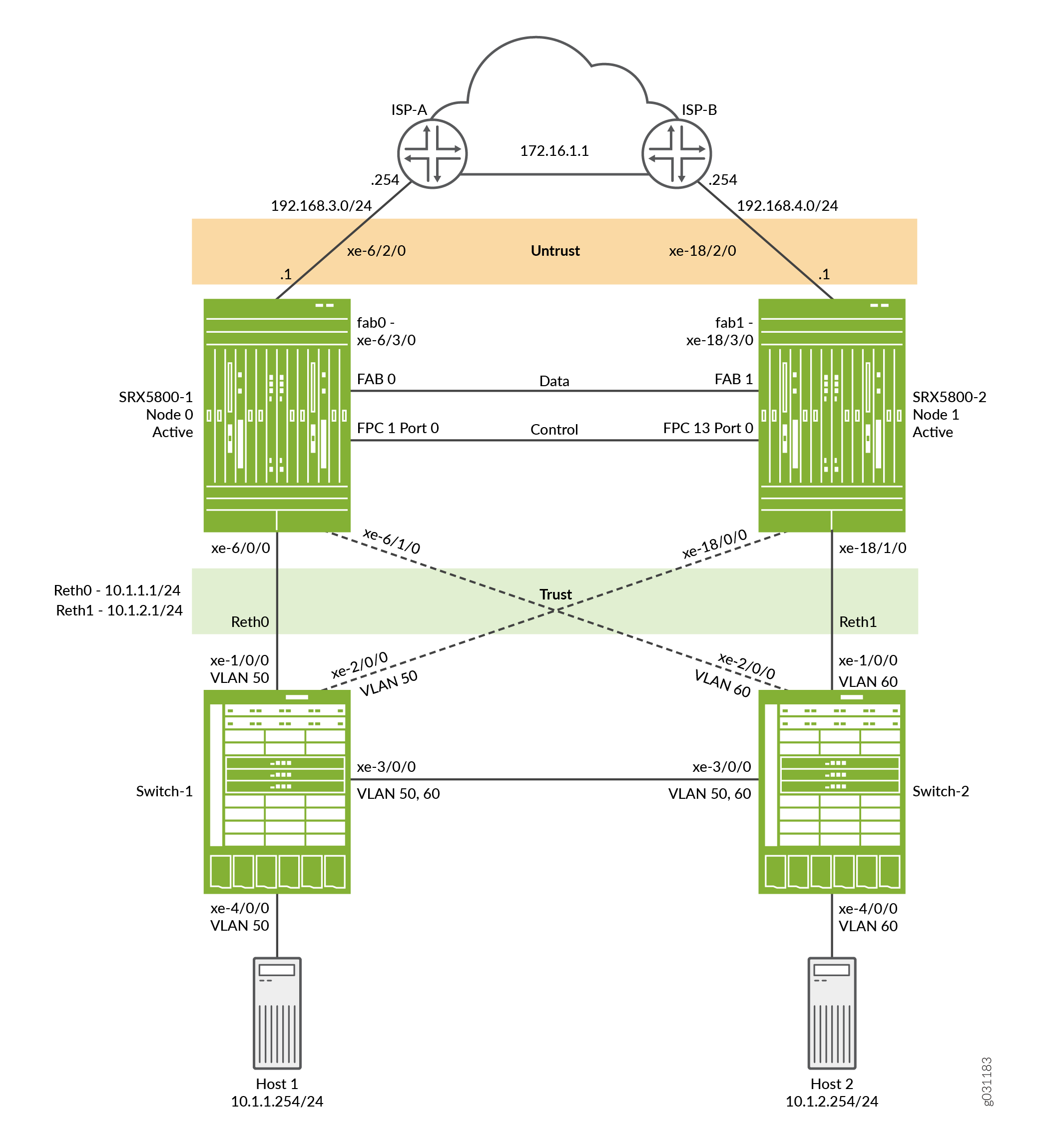 上的主动/主动第 3 层机箱群集拓扑
配置
要配置此示例,请执行以下过程:
配置控制端口
分步程序
为每个设备配置控制端口。
选择 FPC 1 和 FPC 13,因为中心点 (CP) 始终位于群集中最低的 SPC/SPU 上(在本例中为插槽 0)。为获得最大可靠性,请将控制端口放置在与中心点不同的 SPC 上(此示例使用插槽 1 中的 SPC)。
仅 SRX5600 和 SRX5800 设备需要配置控制端口。
-
配置控制端口并提交配置:
user@host# set chassis cluster control-ports fpc 1 port 0
user@host# set chassis cluster control-ports fpc 13 port 0
user@host# commit and-quit
启用群集模式
分步程序
为每个设备分配一个群集 ID 和节点 ID。
通过在每台设备上添加一个群集 ID 和节点 ID,然后重新启动,将两台设备设置为群集模式。您可以通过在 set 命令中包含参数 reboot 来将系统配置为自动启动。
由于分段上只有一个群集,因此此示例使用群集 ID 1,其中设备 SRX5800-1 作为节点 0,设备 SRX5800-2 作为节点 1。
要将两台设备设置为群集模式:
-
在 SRX5800-1(节点 0)上启用群集模式。
user@host> set chassis cluster cluster-id 1 node 0 reboot
-
在 SRX5800-2(节点 1)上启用群集模式。
user@host> set chassis cluster cluster-id 1 node 1 reboot
注意:如果在单个广播域上有多个 SRX 设备群集,请确保为每个群集分配不同的群集 ID,以避免 MAC 地址冲突。
当系统重新启动时,节点将作为一个群集启动。从此时开始,群集的配置将在节点成员之间同步,两台独立的设备作为一台设备运行。
配置群集参数
分步程序
在群集模式下,所有命令和配置都会应用于两个节点。
要配置机箱群集设置:
-
在每台设备上配置一个交换矩阵(数据)端口,以便在流量到达一个节点上的入口接口但离开另一个节点时,能够将流量从一台设备传递到另一台设备。
注意:建议将 10 千兆以太网连接用于主动/主动部署。
user@host# set interfaces fab0 fabric-options member-interfaces xe-6/3/0
user@host# set interfaces fab1 fabric-options member-interfaces xe-18/3/0
-
配置每个设备的 fxp0 接口以进行带外管理。为群集的每个设备(控制平面)分配单独的 IP 地址。
由于 SRX 服务网关机箱群集配置包含在单个通用配置中,因此要仅将配置的某些元素分配给特定成员,请使用称为组的特定于 Junos OS 节点的配置方法。该
set apply-groups ${node}命令使用节点变量来定义如何将组应用于节点。每个节点都能识别其编号,并相应地接受配置。user@host# set groups node0 system host-name SRX5800-1 user@host# set groups node0 interfaces fxp0 unit 0 family inet address 10.52.43.57/19 user@host# set groups node1 system host-name SRX5800-2 user@host# set groups node1 interfaces fxp0 unit 0 family inet address 10.52.52.27/19 user@host# set apply-groups ${node} -
为机箱群集配置冗余组。
每个节点都有冗余组中的接口。冗余组 0 控制控制平面,它定义哪个节点将成为主节点。冗余组 1+ 控制数据平面并包括数据平面端口。此主动/主动群集模式示例使用 2 个具有冗余组 0、1 和 2 的 reth 接口。
作为冗余组配置的一部分,您还必须定义控制平面和数据平面的优先级 — 控制平面首选哪台设备,以及数据平面首选哪台设备。(对于机箱群集,优先级较高者优先。)
注意:控制平面(冗余组 0)和数据平面(冗余组 1+)都可以在不同的机箱上处于活动状态。但是,对于此示例,建议在同一机箱成员上同时激活控制平面和数据平面。冗余组 0 (RG0) 和冗余组 1 (RG1) 默认为节点 0 上的活动状态,而冗余组 2 (RG2) 默认为节点 1 上的活动状态。
user@host# set chassis cluster redundancy-group 0 node 0 priority 129
user@host# set chassis cluster redundancy-group 0 node 1 priority 128
user@host# set chassis cluster redundancy-group 1 node 0 priority 129
user@host# set chassis cluster redundancy-group 1 node 1 priority 128
user@host# set chassis cluster redundancy-group 2 node 0 priority 128
user@host# set chassis cluster redundancy-group 2 node 1 priority 129
-
配置平台上的数据接口,以便在发生数据平面故障切换时,其他机箱群集成员可以无缝接管连接。
定义以下项:
-
群集的最大 reth 接口数,以便系统可以为其分配适当的资源。
user@host# set chassis cluster reth-count 2 -
reth 接口信息,例如接口的 IP 地址。
user@host# set interfaces reth0 unit 0 family inet address 10.1.1.1/24
user@host# set interfaces reth1 unit 0 family inet address 10.1.2.1/24
-
成员接口到 reth 接口的成员资格信息。
user@host# set interfaces xe-6/0/0 gigether-options redundant-parent reth0
user@host# set interfaces xe-6/1/0 gigether-options redundant-parent reth1
user@host# set interfaces xe-18/0/0 gigether-options redundant-parent reth0
user@host# set interfaces xe-18/1/0 gigether-options redundant-parent reth1
-
reth 接口到冗余组的映射。
user@host# set interfaces reth0 redundant-ether-options redundancy-group 1
user@host# set interfaces reth1 redundant-ether-options redundancy-group 2
-
-
配置发生故障时的行为。
每个接口都配置了一个权重值,该值在链路丢失时从冗余组阈值 255 中扣除。当冗余组阈值达到 0 时,该冗余组将故障转移到辅助节点。
注意:如果未启用该
control-link-recovery功能,则需要手册重新启动才能使辅助节点与主节点恢复同步。user@host# set chassis cluster redundancy-group 1 interface-monitor xe-6/0/0 weight 255 user@host# set chassis cluster redundancy-group 2 interface-monitor xe-6/1/0 weight 255 user@host# set chassis cluster redundancy-group 1 interface-monitor xe-18/0/0 weight 255 user@host# set chassis cluster redundancy-group 2 interface-monitor xe-18/1/0 weight 255 user@host# set chassis cluster control-link-recovery
注意:接口上的单个 VLAN 不受监控。仅监控整个接口。
此步骤将完成机箱群集配置。
-
配置不属于 reth 接口的其他接口。这些是通往 ISP 的上游接口。
user@host# set interface xe-6/2/0 unit 0 family inet address 192.168.3.1/24
user@host# set interface xe-18/2/0 unit 0 family inet address 192.168.4.1/24
以下部分介绍如何配置区域、安全策略、NAT、路由和 EX9214 核心交换机以完成部署方案。
配置区域、策略、NAT 和路由
分步程序
配置 reth 接口并将其连接到相应的区域,并定义允许出站流量的安全策略。此外,在本例中,我们将使用默认路由和 NAT 来使终端主机能够访问互联网。
要配置区域、策略、NAT 和路由,请执行以下操作:
-
将接口分配给相应的区域。
user@host# set security zones security-zone trust interfaces reth0.0
user@host# set security zones security-zone trust interfaces reth1.0
user@host# set security zones security-zone untrust interfaces xe-6/2/0.0
user@host# set security zones security-zone untrust interfaces xe-18/2/0.0
-
配置策略以允许从信任区域中的主机到互联网的流量。
user@host# set security policies from-zone trust to-zone untrust policy allow match source-address any
user@host# set security policies from-zone trust to-zone untrust policy allow match destination-address any
user@host# set security policies from-zone trust to-zone untrust policy allow match application any
user@host# set security policies from-zone trust to-zone untrust policy allow then permit
-
为出站流量配置源 NAT。
user@host# set security nat source rule-set internet from zone trust
user@host# set security nat source rule-set internet to zone untrust
user@host# set security nat source rule-set internet rule rule1 match source-address 10.1.0.0/16
user@host# set security nat source rule-set internet rule rule1 then source-nat interface
-
定义默认静态路由,使主机能够访问互联网。
user@host# set routing-options static route 0.0.0.0/0 next-hop 192.168.3.254 user@host# set routing-options static route 0.0.0.0/0 qualified-next-hop 192.168.4.254 preference 7 user@host# set routing-options static route 10.0.0.0/8 next-hop 10.52.63.254 -
配置 OSPF。
user@host# set protocols ospf area 0.0.0.0 interface reth0.0
user@host# set protocols ospf area 0.0.0.0 interface reth1.0
user@host# set protocols ospf area 0.0.0.0 interface reth2.0
user@host# set protocols ospf area 0.0.0.0 interface reth3.0
配置 EX9214-1
分步程序
对于 EX9214-1,以下命令仅提供与 SRX5800 的主动/主动示例相关的配置,尤其是 VLAN、路由和接口配置。
-
配置接口。
user@host# set interfaces xe-1/0/0 unit 0 family ethernet-switching interface-mode access
user@host# set interfaces xe-1/0/0 unit 0 family ethernet-switching vlan members SRX5800-RETH0
user@host# set interfaces xe-2/0/0 unit 0 family ethernet-switching interface-mode access
user@host# set interfaces xe-2/0/0 unit 0 family ethernet-switching vlan members SRX5800-RETH0
user@host# set interfaces xe-3/0/0 unit 0 family ethernet-switching interface-mode trunk
user@host# set interfaces xe-3/0/0 unit 0 family ethernet-switching vlan members SRX5800-RETH1
user@host# set interfaces xe-3/0/0 unit 0 family ethernet-switching vlan members SRX5800-RETH0
user@host# set interfaces ge-4/0/0 unit 0 family ethernet-switching interface-mode access
user@host# set interfaces ge-4/0/0 unit 0 family ethernet-switching vlan members SRX5800-RETH0
注意:终端主机正在发送未标记的流量。
-
配置 VLAN。
user@host# set vlans SRX5800-RETH0 vlan-id 50
user@host# set vlans SRX5800-RETH1 vlan-id 60
-
启用 RSTP。
user@host# set protocols rstp interface all
注意:在此示例中,由于没有第 2 层环路,因此没有严格要求 RSTP。但是,典型环境可能会有更多交换机,这需要启用该协议。
配置 EX9214-2
分步程序
要配置 EX9214-2,请执行以下操作:
-
配置接口。
user@host# set interfaces xe-1/0/0 unit 0 family ethernet-switching interface-mode access
user@host# set interfaces xe-1/0/0 unit 0 family ethernet-switching vlan members SRX5800-RETH1
user@host# set interfaces xe-2/0/0 unit 0 family ethernet-switching interface-mode access
user@host# set interfaces xe-2/0/0 unit 0 family ethernet-switching vlan members SRX5800-RETH1
user@host# set interfaces xe-3/0/0 unit 0 family ethernet-switching interface-mode trunk
user@host# set interfaces xe-3/0/0 unit 0 family ethernet-switching vlan members SRX5800-RETH0
user@host# set interfaces xe-3/0/0 unit 0 family ethernet-switching vlan members SRX5800-RETH1
user@host# set interfaces ge-4/0/0 unit 0 family ethernet-switching interface-mode access
user@host# set interfaces ge-4/0/0 unit 0 family ethernet-switching vlan members SRX5800-RETH1
注意:终端主机正在发送未标记的流量。
-
配置 VLAN。
user@host# set vlans SRX5800-RETH0 vlan-id 50
user@host# set vlans SRX5800-RETH1 vlan-id 60
-
启用 RSTP。
user@host# set protocols rstp interface all
注意:在此示例中,由于没有第 2 层环路,因此没有严格要求 RSTP。但是,典型环境可能会有更多交换机,这需要启用该协议。
验证
确认配置工作正常。
验证机箱群集状态
目的
验证机箱群集状态、故障切换状态和冗余组信息。
行动
在操作模式下,输入命令 show chassis cluster status 。
{primary:node0}
user@host>show chassis cluster status

Monitor Failure codes:
    CS  Cold Sync monitoring        FL  Fabric Connection monitoring
    GR  GRES monitoring             HW  Hardware monitoring
    IF  Interface monitoring        IP  IP monitoring
    LB  Loopback monitoring         MB  Mbuf monitoring
    NH  Nexthop monitoring          NP  NPC monitoring
    SP  SPU monitoring              SM  Schedule monitoring
    CF  Config Sync monitoring

Cluster ID: 1
Node   Priority Status         Preempt Manual   Monitor-failures

Redundancy group: 0 , Failover count: 1
node0  129      primary        no      no       None
node1  128      secondary      no      no       None

Redundancy group: 1 , Failover count: 1
node0  129      primary        no      no       None
node1  128      secondary      no      no       None

Redundancy group: 2 , Failover count: 0
node0  128      secondary      no      no       None
node1  129      primary        no      no       None
意义
示例输出显示主节点和辅助节点的状态,并且没有手册故障转移。
验证机箱群集接口
目的
验证有关机箱群集接口的信息。
行动
在操作模式下,输入命令 show chassis cluster interfaces 。
{primary:node0}
user@host> show chassis cluster interfaces

Control link status: Up

Control interfaces:
    Index   Interface   Monitored-Status   Internal-SA
    0       fxp1        Up                 Disabled

Fabric link status: Up

Fabric interfaces:
    Name    Child-interface    Status
                               (Physical/Monitored)
    fab0    xe-6/3/0           Up   / Up
    fab0
    fab1    xe-18/3/0          Up   / Up
    fab1

Redundant-ethernet Information:
    Name         Status      Redundancy-group
    reth0        Up          1
    reth1        Up          2

Redundant-pseudo-interface Information:
    Name         Status      Redundancy-group
    lo0          Up          0

Interface Monitoring:
    Interface         Weight    Status    Redundancy-group
    ge-6/0/0           255       Up        1
    ge-18/0/0          255       Up        1
    ge-6/1/0           255       Up        2
    ge-18/1/0          255       Up        2
意义
示例输出提供有关控制链路和结构链路的状态信息。它还显示每个 reth 接口的状态、权重值和冗余组。
验证机箱群集统计信息
目的
验证有关机箱群集服务和控制链路统计信息(发送和接收的心跳)、交换结构链路统计信息(发送和接收的探查)以及为服务发送和接收的实时对象 (RTO) 数的信息。
行动
在操作模式下,输入命令 show chassis cluster statistics 。
{primary:node0}
user@host> show chassis cluster statistics

Control link statistics:
    Control link 0:
        Heartbeat packets sent: 258689
        Heartbeat packets received: 258684
        Heartbeat packets errors: 0
Fabric link statistics:
    Child link 0
        Probes sent: 258681
        Probes received: 258681
Services Synchronized:
    Service name                              RTOs sent    RTOs received
    Translation context                       0            0
    Incoming NAT                              0            0
    Resource manager                          6            0
    Session create                            161          0
    Session close                             148          0
    Session change                            0            0
    Gate create                               0            0
    Session ageout refresh requests           0            0
    Session ageout refresh replies            0            0
    IPSec VPN                                 0            0
    Firewall user authentication              0            0
    MGCP ALG                                  0            0
    H323 ALG                                  0            0
    SIP ALG                                   0            0
    SCCP ALG                                  0            0
    PPTP ALG                                  0            0
    RPC ALG                                   0            0
    RTSP ALG                                  0            0
    RAS ALG                                   0            0
    MAC address learning                      0            0
    GPRS GTP                                  0            0
意义
使用示例输出:
-
验证 是否 Heartbeat packets sent 在递增。
-
验证 是否 Heartbeat packets received 是接近 的 Heartbeats packets sent数字。
-
验证 是否 Heartbeats packets errors 为零。
这将验证检测信号数据包的传输和接收是否没有错误。
验证机箱群集控制平面统计信息
目的
验证有关机箱群集控制平面统计信息(发送和接收的心跳)和交换结构链路统计信息(发送和接收的探查)的信息。
行动
在操作模式下,输入命令 show chassis cluster control-plane statistics 。
{primary:node0}
user@host>show chassis cluster control-plane statistics

Control link statistics:
    Control link 0:
        Heartbeat packets sent: 258689
        Heartbeat packets received: 258684
        Heartbeat packets errors: 0
Fabric link statistics:
    Child link 0
        Probes sent: 258681
        Probes received: 258681
意义
使用示例输出:
-
验证 是否 Heartbeat packets sent 在递增。
-
验证 是否 Heartbeat packets received 是接近 的 Heartbeats packets sent数字。
-
验证 是否 Heartbeats packets errors 为零。
这将验证检测信号数据包的传输和接收是否没有错误。
验证机箱群集数据平面统计信息
目的
验证有关为服务发送和接收的实时对象 (RTO) 数量的信息。
行动
在操作模式下,输入命令 show chassis cluster data-plane statistics 。
{primary:node0}
user@host>show chassis cluster data-plane statistics

Services Synchronized:
    Service name                              RTOs sent    RTOs received
    Translation context                       0            0
    Incoming NAT                              0            0
    Resource manager                          6            0
    Session create                            161          0
    Session close                             148          0
    Session change                            0            0
    Gate create                               0            0
    Session ageout refresh requests           0            0
    Session ageout refresh replies            0            0
    IPSec VPN                                 0            0
    Firewall user authentication              0            0
    MGCP ALG                                  0            0
    H323 ALG                                  0            0
    SIP ALG                                   0            0
    SCCP ALG                                  0            0
    PPTP ALG                                  0            0
    RPC ALG                                   0            0
    RTSP ALG                                  0            0
    RAS ALG                                   0            0
    MAC address learning                      0            0
    GPRS GTP                                  0            0
意义
示例输出显示为各种服务发送和接收的 RTO 数。
验证机箱群集冗余组状态
目的
验证冗余组的状态。
行动
在操作模式下,输入命令 chassis cluster status redundancy-group 。
{primary:node0}
user@host>show chassis cluster status redundancy-group 1

Monitor Failure codes:
    CS  Cold Sync monitoring        FL  Fabric Connection monitoring
    GR  GRES monitoring             HW  Hardware monitoring
    IF  Interface monitoring        IP  IP monitoring
    LB  Loopback monitoring         MB  Mbuf monitoring
    NH  Nexthop monitoring          NP  NPC monitoring
    SP  SPU monitoring              SM  Schedule monitoring
    CF  Config Sync monitoring

Cluster ID: 1
Node   Priority Status         Preempt Manual   Monitor-failures

Redundancy group: 1 , Failover count: 1
node0  129      primary        no      no       None
node1  128      secondary      no      no       None
意义
示例输出显示冗余组 1 运行正常,没有抢占、手册故障切换或其他故障。
使用日志进行故障排除
目的
查看系统日志文件,确定任何机箱群集问题。您应该查看两个节点上的系统日志文件。
行动
在操作模式下,输入以下 show log 命令。
user@host> show log jsrpd
user@host> show log chassisd
user@host> show log messages
user@host> show log dcd
user@host> show traceoptions
结果
在操作模式下,输入 show configuration 命令以确认您的配置。如果输出未显示预期的配置,请重复此示例中的说明以更正配置。
groups {
    node0 {
        system {
            host-name SRX5800-1;
        }
        interfaces {
            fxp0 {
                unit 0 {
                    family inet {
                        address 10.3.5.1/24;
                    }
                }
            }
        }
    }
    node1 {
        system {
            host-name SRX5800-2;
        }
        interfaces {
            fxp0 {
                unit 0 {
                    family inet {
                        address 10.3.5.2/24;
                    }
                }
            }
        }
    }
}
apply-groups “${node}”;
chassis {
    cluster {
        control-link-recovery;
        reth-count 2;
        control-ports {
            fpc 1 port 0;
            fpc 13 port 0;
        }
        redundancy-group 0 {
            node 0 priority 129;
            node 1 priority 128;
        }
        redundancy-group 1 {
            node 0 priority 129;
            node 1 priority 128;
            interface-monitor {
                xe-6/0/0 weight 255;
                xe-18/0/0 weight 255;
            }
        }
        redundancy-group 2 {
            node 0 priority 128;
            node 1 priority 129;
            interface-monitor {
                xe-6/1/0 weight 255;
                xe-18/1/0 weight 255;
            }
        }
    }
}
interfaces {
    xe-6/0/0 {
        gigether-options {
            redundant-parent reth0;
        }
    }
    xe-6/1/0 {
        gigether-options {
            redundant-parent reth1;
        }
    }
    xe-6/2/0 {
        unit 0 {
            family inet {
                address 192.168.3.1/24;
            }
        }
    }
    xe-18/0/0 {
        gigether-options {
            redundant-parent reth0;
        }
    }
    xe-18/1/0 {
        gigether-options {
            redundant-parent reth1;
        }
    }
    xe-18/2/0 {
        unit 0 {
            family inet {
                address 192.168.4.1/24;
            }
        }
    }
    fab0 {
        fabric-options {
            member-interfaces {
                xe-6/3/0;
            }
        }
    }
    fab1 {
        fabric-options {
            member-interfaces {
                xe-18/3/0;
            }
        }
    }
    reth0 {
        redundant-ether-options {
            redundancy-group 1;
        }
        unit 0 {
            family inet {
                address 10.1.1.1/24;
            }
        }
    }
    reth1 {
        redundant-ether-options {
            redundancy-group 2;
        }
        unit 0 {
            family inet {
                address 10.1.2.1/24;
            }
        }
    }
}
routing-options {
    static {
        route 0.0.0.0/0 {
            next-hop 192.168.3.254;
            qualified-next-hop 192.168.4.254 {
                preference 7;
            }
        }
    }
}
security {
    nat {
        source {
            rule-set internet {
                from zone trust;
                to zone untrust;
                rule rule1 {
                    match {
                        source-address 10.1.0.0/16;
                    }
                    then {
                        source-nat {
                            interface;
                        }
                    }
                }
            }
        }
    }
    policies {
        from-zone trust to-zone untrust {
            policy allow {
                match {
                    source-address any;
                    destination-address any;
                    application any;
                }
                then {
                    permit;
                }
            }
        }
    }
    zones {
        security-zone trust {
            interfaces {
                reth0.0;
                reth1.0;
            }
        }
        security-zone untrust {
            interfaces {
                xe-6/2/0.0;
                xe-18/2/0.0;
            }
        }
    }
}
如果完成设备配置,请从配置模式进入。commit