Configurar a distribuição de núcleo de malha de campus
Siga estas etapas para configurar uma topologia de distribuição de núcleo para sua malha de campus.
As malhas de campus da Juniper Networks oferecem uma única solução EVPN-VXLAN baseada em padrões que você pode implantar em qualquer campus. A solução de distribuição de núcleo de malha de campus estende a malha EVPN para conectar VLANs em vários edifícios. Essa arquitetura de rede inclui as camadas de núcleo e distribuição que se integram com a camada de comutação de acesso através do LACP padrão.
Para obter mais informações básicas sobre arquiteturas de distribuição de núcleo de malha de campus, consulte os seguintes documentos:
Em topologias criadas na nuvem da Mist após as atualizações de maio de 2025, a Mist detecta e relata automaticamente quaisquer loops de EVPN e endereços MAC duplicados. Esses problemas são exibidos na página Insights do switch.
-
Detecção de loop EVPN — a detecção de loop PE-CE leve EVPN-VXLAN ajuda a detectar e interromper loops Ethernet LAN em portas de acesso ou leaf-to-server downstream. Esse recurso pode detectar loops causados por problemas como componentes de malha com fio incorreto ou switches de terceiros conectados incorretamente à malha. Para que esse recurso funcione, o switch deve executar o Junos OS versão 24.4R1 ou posterior. Para obter mais informações, consulte EVPN-VXLAN Lightweight Leaf to Server Loop Detection.
-
Detecção de endereço MAC duplicado — identifica e mitiga problemas decorrentes do movimento do endereço MAC (mobilidade MAC) entre diferentes interfaces ou dispositivos em ambientes EVPN. Embora alguma mobilidade MAC seja esperada (por exemplo, quando um dispositivo realmente se move), mudanças rápidas podem indicar problemas como loops de rede ou configurações incorretas. Para obter mais informações, consulte Configuração da detecção de loop para endereços MAC duplicados.
Boas práticas de configuração de malha de campus
- Configure VLANs no nível do modelo de switch e importe-as durante a configuração da malha do campus. O modelo deve ser a única fonte de verdade para todas as VLANs e perfis de porta, a menos que seja especificamente exigido no nível do switch ou do site.
- Na camada de acesso, evite usar perfis de porta de tronco que permitam todas as VLANs, a menos que seja explicitamente necessário.
- Crie configurações de rede VRF e VRF por meio da malha do campus, não por meio de modelos de switch.
- Crie atribuições de porta por função e substitua a configuração em um dispositivo individual conforme necessário.
- Gerencie a configuração do relé DHCP por meio do fluxo de fluxo de trabalho de malha de campus, exceto para os dispositivos de bloco de serviço.
Para configurar a distribuição de núcleo de malha de campus:
- Se você quiser criar a malha de campus para um site, selecione o site na lista suspensa ao lado do cabeçalho da página. Se você deseja criar a malha de campus para toda a organização, selecione Organização inteira na lista suspensa.
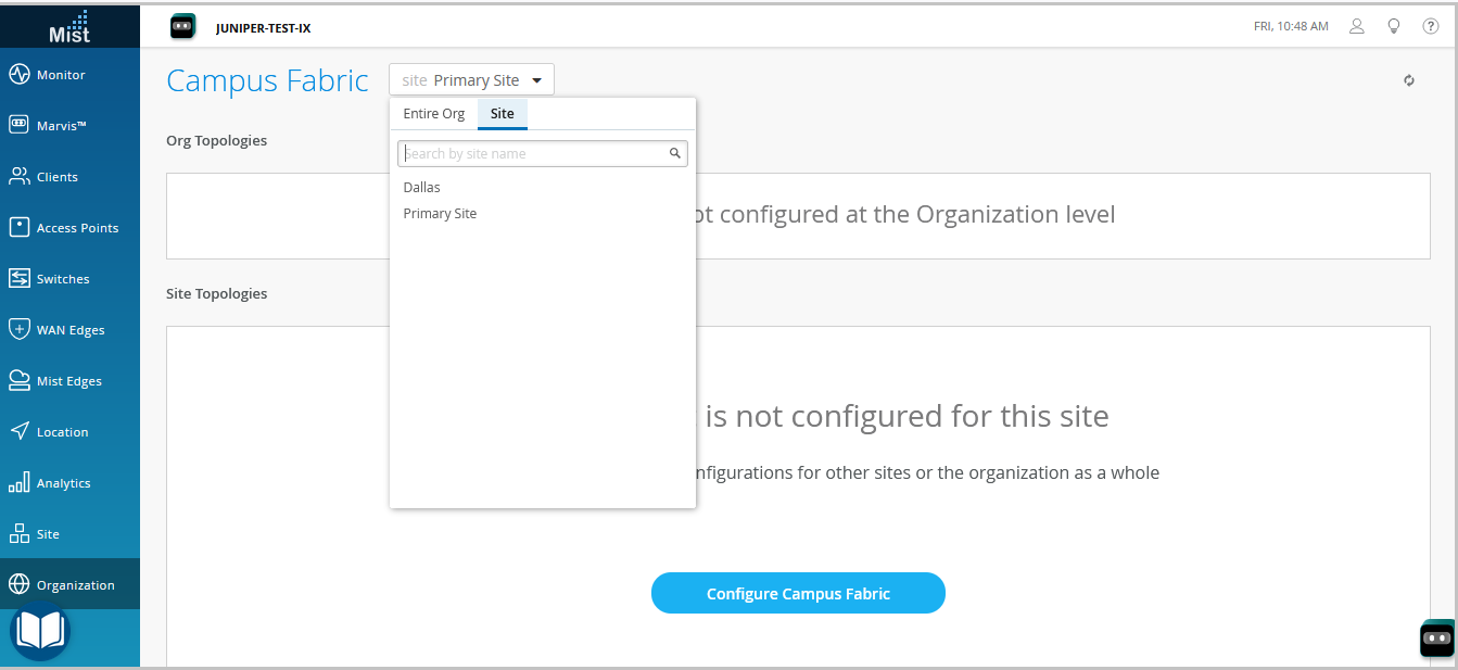
Você pode usar uma topologia de malha de campus no nível da organização para construir uma arquitetura de todo o campus com vários edifícios. Caso contrário, crie uma malha de campus específica do local com um único conjunto de switches de núcleo, distribuição e acesso.
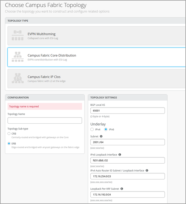
- Selecione o tipo de topologia Distribuição de núcleo de malha de campus.
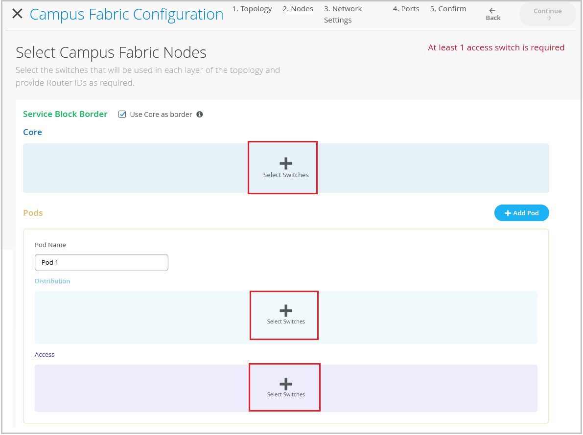
- Clique em Continuar para ir para a guia Nós, onde você pode selecionar os dispositivos que fazem parte da implantação da malha de campus.
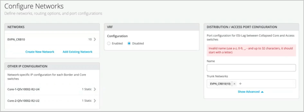
- Defina as configurações de rede, conforme descrito abaixo:
- Clique em Continuar para ir para a guia Portas, onde você pode configurar as portas e criar uma conexão entre os switches de núcleo, distribuição e camada de acesso.
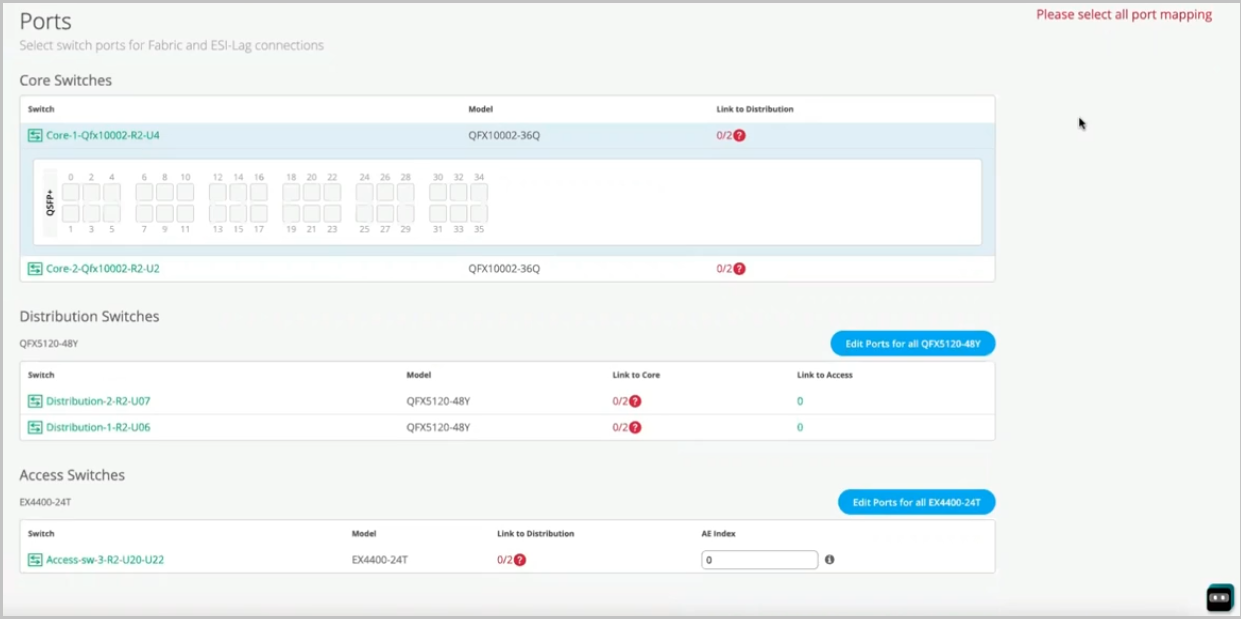
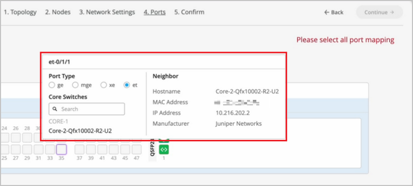
- Configure as portas do switch na camada de núcleo conforme descrito abaixo:
- Selecione um switch na seção Núcleo para abrir o painel da porta do switch.
- No painel de portas do switch principal, selecione uma porta que você deseja configurar.
- Especifique um tipo de porta (por exemplo,
geouxe). - Escolha o switch de distribuição no qual o link deve terminar. Você precisa configurar todas as portas que precisam fazer parte da malha do campus.
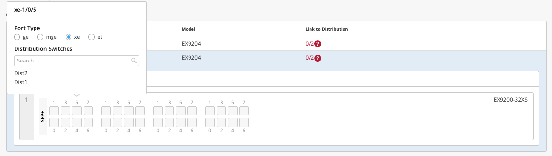
Para configurar portas de switch na camada de distribuição:
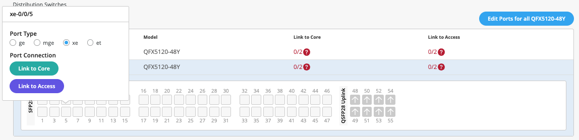 Para configurar as portas do switch na camada de acesso:
Para os switches de acesso, selecione apenas as interfaces que devem ser usadas para interconectar com o switch de distribuição. O sistema agrupa todas as interfaces em um único pacote Ethernet por meio da opção de índice AE. Você pode especificar um valor de índice AE para os dispositivos de acesso.
Se você quiser exibir as informações de configuração e status de uma porta específica, passe o mouse sobre a caixa numerada que representa essa porta na interface do usuário do painel de portas.
- Clique em Fechar Configuração de malha de campus.
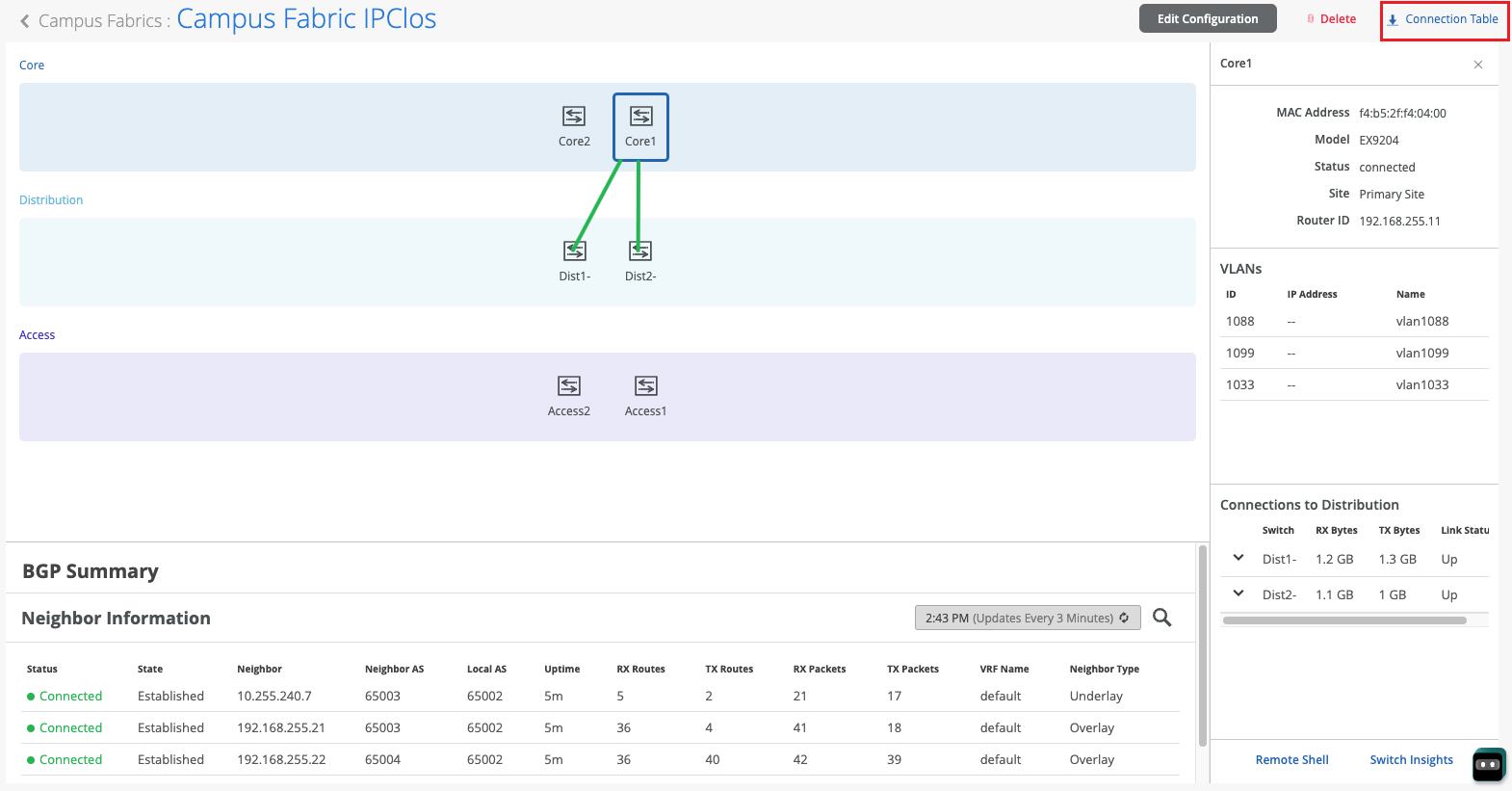
Depois que a Mist construir a malha do campus, ou enquanto estiver construindo a malha, você poderá baixar a tabela de conexão. A tabela de conexão representa o layout físico da malha do campus. Você pode usar esta tabela para validar todas as interconexões de switch para os dispositivos que participam da construção da malha física do campus. Clique em Tabela de conexão para baixá-la (formato .csv).
For a demo, watch the following video:
Hello and welcome to this new edition of Wired Assurance. My name is Rohan Chadha and I am a part of the MIST product management team. Today we'll be talking about deployment of campus fabric core distribution topology with Wired Assurance.
This particular EVPN topology is one of the three main topologies recommended by Juniper for EVPN VxLAN in campus. Today we'll be talking about how to deploy this using Wired Assurance and I assure you none of this deployment will include any CLI configuration and we'll use the UI throughout with just a click of a few buttons. So let's just jump right into it and I'll walk you through the four steps to deploy this topology.
Before we begin, let's talk about the building blocks of campus fabric core distribution. What are the devices that we're going to use today? And what is essentially campus fabric core distribution? So today we'll be using two core devices that are QFX 10,000 use. We'll be using two distribution devices that are QFX 5120Y and we'll be using one access switch for the purposes of this video.
And this particular device is an EX440024T, a copper switch. In this case, it's a virtual chassis. You can use a standalone or you can use a virtual chassis for an access device in campus fabric core distribution.
Before we jump into building the topology in four steps, let's talk about if campus fabric core distribution is right for you or your network environment. I would highly recommend you watch the other video by Rick Bartosik in which he explains why should you use campus fabric core distribution versus, let's say, an IP CLO or an EVPN multi-homing topology. So if you're new to EVPN makes land and you're trying to explore this area, I would highly recommend you go watch that video.
But if you're sure that you want to use this topology and you want to learn how to build it, you're in the right spot. One other thing that I'd like to point out to you on this page is that all of these devices are not being managed by Wired Assurance at this moment. And what does that mean? That means that they are only in monitoring mode.
As you can see, the configuration is not being managed by MIST. There is a reason why I'm demoing it a certain way and I'll show you why. So none of these devices are being managed.
The configuration will not be pushed to the devices unless we explicitly ask the UI to do it. So towards the end of the video, I'll show you why we want it to be a certain way. So let's click on organization and under Wired, we'll click on campus fabric.
We'll build a site-based campus fabric. There is also something called an org-based campus fabric. And what that means is you can build a campus fabric for an entire organization using pods from multiple sites.
But today for the purposes of this video, we'll be building only a site-based campus fabric, campus fabric core distribution as they call it. So let's click on configure campus fabric. And as you can see that at the time of making of this video, campus fabric core distribution along with campus fabric IP Clo are in beta state.
So let's talk about choosing a campus fabric topology. As I mentioned earlier, if you're sure that you want to build campus fabric core distribution, then this is the right place for you. If you're not, then go watch the other video.
But let's talk about what campus fabric core distribution is. It is essentially a two-layer EVPN VXLAN fabric, which involves a core layer and a distribution layer. If you look at this diagram on the left side, you see a horizontal line.
This horizontal line basically differentiates what is EVPN VXLAN configured versus what is not. As you can see, the top is a core layer and a distribution layer. Below the horizontal line are access devices that are basically dual home to the distribution boxes.
These access devices are pure layer two dummy devices that can run LACP, but that's not a requirement. You can also directly connect servers or any other devices that you would like to single home directly to these distribution devices, and that can come outside of the campus fabric core distribution workflow. That is possible.
So let's begin by configuring a topology name. There are two kinds of topologies that we can build within campus fabric core distribution, CRB as well as ERB. As you can see on the screen, it's centrally routed and edge routed.
So centrally routed means routing on the core device, and edge routed means routing on the edge, which in this case, our edge is distribution. For the purposes of this video, we'll be building a campus fabric core distribution that is CRB. So let's give it a name.
After you've given a topology name, we have some other default settings that do not need to be changed if there isn't a reason. These are basically the overlay and the underlay settings. For this campus fabric core distribution, we do IBGP in the overlay, and we use EBGP in the underlay.
As you can see, we have 65,000 local is that will be assigned to all the devices in the overlay, and we have 65,001 that will be sequentially incremented on any device that you use in this fabric. All of these settings will be taken care of by campus fabric. As a user, you do not have to manually configure any of these settings on the device itself, as I mentioned earlier.
The loopback prefix is the prefix assigned to loopback interfaces for every VTEP in campus fabric core distribution. It's slash 24 by default. If you do not want to use this number, you can reduce it.
If your campus fabric core distribution is a smaller fabric, let's say 5 to 10 devices, something like a slash 28 would work for you. Subnet in this particular setting is basically the subnet that as a user, you would provide us, or you can use this default subnet. This will be used for the IP address allocation for the fabric links between the core and the distribution devices.
Again, all of this will be done and taken care of by campus fabric itself. The second step is basically selecting the campus fabric nodes. What nodes would you want to be a part of core distribution and access layer? There are a few requirements.
The first one that we see on the screen is service blog border. Let me talk a little about what this is. So if you're someone who would want their network environment core devices to be lean spine, and what that means is if you do not want the firewall or the WAN or DHCP DNS NTP services to be connected to the core devices, you can use something that's called service blog.
This service blog basically connects to the core and you can connect all of your services, including the connectivity to the cloud and your data centers in this particular service blog. For the purposes of this video, I'm going to keep it simple and we're going to be just building a fabric here and connecting. The service blog will not be a part of this video.
So we'll go ahead and select two devices that are a part of the core layer and that is, as I mentioned, core one and core two. We will select two distribution devices, distribution one and distribution two. As you can see in this little dropdown, there is all the information provided to you at your fingertips, including the name and the model.
And for the access layer, we'll be selecting a virtual chassis that is access switch three. Once you've selected all the devices, you can verify by clicking on these. You also need to provide the router IDs here.
These router IDs are used for loopback interfaces. These loopback interfaces are used to pair with each other for building the VX LAN tunnels. One more thing that I'd like to point out is that once you build the fabric, you can always come back and add more devices and you can scale as much as you would like.
You can add more distribution devices. You can add more access devices based on your network environment needs. So you do not have to connect all the devices in the same setting.
We understand that network environment needs grow. And without any impact to other devices or the network operations itself, you can always come in and add more access devices later if there is a need. The third step is basically to provide networks.
And if you'd like to do some segmentation between those networks, we have VRF settings as well for that. For networks, you can either create a new network. And I'll go and create a new network here.
And we'll call it EVPN-CRB. And I'll give it a VLAN ID 10. And I'll give it a VLAN subnet of 192.160.10.1.0.24. And then I'll assign it a virtual gateway.
This virtual gateway will be used on your gateways depending on if you've chosen a CRB or an ERB network. Once you've created a network, you can see that two IP addresses have automatically been chosen for two core devices. This is where the gateways will be set for this fabric.
And as you can see, since we chose CRB as our topology, core 1 and core 2 will have these two different IRB addresses on their devices. And that will be 192.160.10.2 and 10.3. And we know that 10.1 will be the virtual gateway since we've manually assigned that. We can go ahead and either create more networks or we can also add an existing network.
An existing network is basically something that is being used in your existing site. And in this case, this site called Bangalore-site has a bunch of devices. So we're going to go and choose one and two VLANs that are being used on other devices.
And we'll try to inherit these. What this does is it reduces our work of configuring VLANs manually time and again on every device. So as we can see, 4091 on the subnet and virtual gateway has been inherited without me inputting anything again.
So now we have three VLANs for which all of the gateways will reside on the core devices as we asked for. But what if you do not want the gateways to reside on the core and instead you would like the gateways to reside on outside the fabric, perhaps the firewall or the VAN itself, or perhaps your gateways are in the data center, right? That is an option as well. And that is something that's called bridge overlay.
We can create a new network. Let's call it VLAN 100. And we'll assign a VLAN ID 100.
And we don't have to assign the subnet or the virtual gateway. What this does is VLAN 100 will be a part of the fabric or VNI will be assigned to it and it will be existing on all devices. However, the gateway for VLAN 100 will not exist on the fabric.
And the assumption here is that it will exist somewhere outside the fabric. So it will be a layer to stretch from the access device all the way until where the gateway exists. And it could be the firewall or the router if that exists before.
So now that we've spoken about networks, let's talk about how can you segment these networks using VRF. I'll go ahead and enable these instances for VRFs. And I'll try and create some VRFs here where I'll try to keep CRB10 as a part of one VRF.
And then I'll keep the other two VLANs as a part of VRF2. What this does is it segments the traffic between VRF1 and VRF2. If you would like more security and segmentation where you want to keep these networks separate and have different routing tables, this is an option for you.
You can also add extra routes if that is a requirement for your network needs. The last step on this page is to assign a name to the distribution access configuration. Once you've built the fabric, there will be an ESL lag between your distribution and your access devices.
Your access devices will be dual-homed to your distribution devices. So let's give it a name and call it EBPN-ESI. We've automatically taken all four networks that you assigned to the fabric and you added it to the trunk networks list, assuming that all of them will be a part of the fabric and the ESI lag.
If for some reason you would not want to have any of the VLANs as a part of the ESI lag, you can always come in and remove that here. There are other properties that you can change. Most of them are default.
If you would like to change the MTU or enable storm control, or if you would like to set up a MAC limit, that is an option as well for you. The last and final step is to assign how these ports are connected to each other. So far, we've picked the devices.
We've picked the VLANs and the VRFs that we want, but we haven't really told Campus Fabric how to connect these devices. So what I'm going to do is I'm going to go ahead and connect these devices, and I'll fast-forward the video so you don't have to go through each of the connections that I picked. So as you can see here, I've connected all these devices to each other.
I've connected two links from the core to the distribution, and then upwards as well from distribution to the core, and then from distribution to access, I've connected two links as well. As you can see, we support a virtual chassis in the access layer, so you can very well use that as well here. And if you'd like to change the AE index number, that is an option as well, as long as it is within the AE index range.
So this was the last and final step. We'll hit Continue, and this is our final step to verify you've built the fabric at this point. Ensure that you have selected the right VLANs, your IP addresses on a per-device level that is selected here as you'd like it to be.
Verify your connections. Is the core connected to the right distribution devices? And as we can see, and as an example, this is our bridged overlay design wherein VLAN 100 does not have an IP address, and that means that it exists somewhere outside the fabric. Go ahead and hit Apply Changes, and click Confirm.
At this point, as I mentioned earlier, the devices are not being managed by MIST, and let's go to the switches, and let's look at each device, and let's understand the configuration that is being pushed here. So before I go through the UI and show you how the configuration is being displayed here in terms of VLANs and VRFs, let's talk about the configuration. If you're running a brownfield environment, what that means is if you have an existing campus fabric, and you are trying to convert to a wireless assurance-based campus fabric, and you do not want to afford any downtime, you can come in, you can onboard your devices to the cloud, but do not manage the devices.
Once you build the fabric, ensure that all the configurations are there. We have a nice utility called Download Genos Config. Without logging into the device, you can ensure that the configuration that you wanted to be on the device is there.
Now, this configuration is the point of view of the cloud, as in wired assurance. Wired assurance, once you turn on Manage by MIST, and you click Save, all the configuration through the CLI will be overwritten, and wired assurance will be the source of truth. So if you look at this configuration, you'll see that we've configured your underlay BGP, we've configured overlay BGP.
In your underlay BGP, we have two neighbors from core one to two distribution devices. Similarly, we have two overlay between core one and distribution one and distribution two. We have the appropriate EVPN configuration.
And similarly, we have the gateways on the core devices with the appropriate virtual gateway. As you can see, we have set appropriate Jumbo MTUs. If there's any configuration that you think does not match your requirement, you can always add or delete using the additional CLI commands.
So if, let's say, you would like to add an existing MTU configuration that is not supported by the UI, let's say, you can always come in and add it to the additional CLI command box. So going back to the configuration, we see that we have the gateways defined. We have the routing instances defined as we did for your segregation of the networks, right? So we can look that vRF1 has a particular network that's a part of it.
And similarly, vRF2 has two networks that are a part of it, and then appropriate routing policies that are needed to talk between the four VTEPs that is there as well. And similarly, all the VLANs that you want are here as well. If there's any configuration, as I mentioned, that can always be added by additional CLI commands.
So now let's go ahead and enable Manage by MIST. So as I mentioned earlier, let's go ahead and enable Manage by MIST. And we can do that for all devices in just a single click.
We do not have to manually do that for all devices. So I click on this particular checkmark next to Status and click on More and Enable Switch Configuration. As you can see, there is a warning here that says that if you have anything that is assigned via the CLI, please ensure that that will be overwritten.
So please take care of that. So what this does is at this point, all of the configuration that we built through the fabric will be pushed to the devices. Your responsibility as a network administrator is to ensure that the configuration that you've been managing through the CLI is the same as the configuration that you see in the downloaded configuration file.
And if you see that there is something that's missing, then you need to rectify that or add through additional CLI commands or perhaps go back to the Campus Fabric and edit the fields provided there. So now that we've reviewed the configuration for Campus Fabric core distribution, let's have a look at the topology itself. And we assume that it's been a while.
So BGP would have come up by now in the underlay and overlay and also the tunnels would have established between the core and the distribution devices. So as you can see, I am in the EVPN-CRV topology that I named and I can see two core devices, two distribution and one access. As I can see, if I click on the core device, all the properties that we saw earlier are available as well.
You would see some green and red links and they are not just the status of that link, but they also depict the traffic flow. So what I mean by that is if you see a thick link, that basically tells you that there's more traffic between those two devices versus if you look at distribution and access. So a good point of comparison would be if the link between core 1 and distribution 2 is thicker than distribution and core 2, you would know that there is more traffic passing through the left link versus the right link.
And that's a very useful way to understand how the traffic flow is working and if, you know, some sort of equal path load balancing is in play or not. So now that we've reviewed the topology itself, we know that since we know we see all these green links, but what if you saw red links and what if you saw some BGP issues over there or if you were seeing some errors? We can always click on a particular device and click on switch insights and see what's happening on that box. And we know for a fact that there are DDoS violations happening.
DDoS violations aren't a problem all the time, but if something's happening repetitively, then that is something that needs to be looked into. We see that there are a bunch of DDoS violations here, but we also see that at the time when we built the topology, the last BGP pure state change was open confirmed to established. Of course, we know that looking at the green links that the neighborhood is up, but if it wasn't, you can always come ahead and look at the switch insights and see that your BGP has gone through its regular steps of coming to an established state.
If for whatever reason, you'd also like to look at the device itself and log into the CLI, if you're used to operating a device a certain way, we've also provided an option for you to click on the remote shell for any device and a pop up window will open right here on the screen, using which you can run any outputs as you'd like. So let's go ahead and check BGP summary as we saw earlier. As we can see, BGP has been up here for 42 minutes.
Let's look at our EVPN database. We see a bunch of MAC addresses in the EVPN database. We see some updated timestamps as well.
Let's look at the Ethernet switching MAC table as well. Of course, we know that all of these devices have been populated. There are a bunch of devices that we have that are locally connected to this particular core device.
Now that we've looked at the topology itself, we know that the topology is up and running. What do you do on day two when your network environment requirements grow? You want to access more devices? You want to add more distribution devices? You can always edit the configuration and add more devices as your needs grow. There is no limit to the number of devices you can add.
There's always a minimum requirement, but there's no maximum limitation here. What if you want to add more networks? You want to do some more segmentation? Similar to what we showed you earlier, you can always come in and create new networks or add existing networks. Nothing changes really from that point.
You can always come in and modify the connectivity between these devices. This concludes our session for EVPN Campus Fabric Core Distribution. I hope that there are some good takeaways for you from this video.
If there's input for us, please send me an email at archada.juniper.net. Thank you.