IPv4 Traffic Over Layer 3 VPNs
Understanding IPv4 Route Distribution in a Layer 3 VPN
Within a VPN, the distribution of VPN-IPv4 routes occurs between the PE and CE routers and between the PE routers (see Figure 1).
This section discusses the following topics:
- Distribution of Routes from CE to PE Routers
- Distribution of Routes Between PE Routers
- Distribution of Routes from PE to CE Routers
Distribution of Routes from CE to PE Routers
A CE router announces its routes to the directly connected PE
router. The announced routes are in IPv4 format. The PE router places
the routes into the VRF table for the VPN. In the Junos OS, this is
the routing-instance-name.inet.0 routing table,
where
routing-instance-name
is the
configured name of the VPN.
The connection between the CE and PE routers can be a remote connection (a WAN connection) or a direct connection (such as a Frame Relay or Ethernet connection).
CE routers can communicate with PE routers using one of the following:
-
OSPF
-
RIP
-
BGP
-
Static route
Figure 2 illustrates how routes are distributed from CE routers to PE routers. Router PE1 is connected to two CE routers that are in different VPNs. Therefore, it creates two VRF tables, one for each VPN. The CE routers announce IPv4 routes. The PE router installs these routes into two different VRF tables, one for each VPN. Similarly, Router PE2 creates two VRF tables into which routes are installed from the two directly connected CE routers. Router PE3 creates one VRF table because it is directly connected to only one VPN.
Distribution of Routes Between PE Routers
When one PE router receives routes advertised from a directly connected CE router, it checks the received route against the VRF export policy for that VPN. If it matches, the route is converted to VPN-IPv4 format—that is, the 8-byte route distinguisher is prepended to the 4-byte VPN prefix to form a 12-byte VPN-IPv4 address. The route is then tagged with a route target community. The PE router announces the route in VPN-IPv4 format to the remote PE routers for use by VRF import policies. The routes are distributed using IBGP sessions, which are configured in the provider’s core network. If the route does not match, it is not exported to other PE routers, but can still be used locally for routing, for example, if two CE routers in the same VPN are directly connected to the same PE router.
The remote PE router places the route into its bgp.l3vpn.0 table if the route passes the import policy on the IBGP session between the PE routers. At the same time, it checks the route against the VRF import policy for the VPN. If it matches, the route distinguisher is removed from the route, and it is placed into the VRF table (the routing-instance-name.inet.0 table) in IPv4 format.
Figure 3 illustrates how Router PE1 distributes routes to the other PE routers in the provider’s core network. Router PE2 and Router PE3 each have VRF import policies that they use to determine whether to accept routes received over the IBGP sessions and install them in their VRF tables.
When a PE router receives routes advertised from a directly connected CE router (Router PE1 in Figure 3), it uses the following procedure to examine the route, convert it to a VPN route, and distribute it to the remote PE routers:
-
The PE router checks the received route using the VRF export policy for that VPN.
-
If the received route matches the export policy, the route is processed as follows:
-
The route is converted to VPN-IPv4 format—that is, the 8-byte route distinguisher is prepended to the 4-byte VPN prefix to form the 12-byte VPN-IPv4 address.
-
A route target community is added to the route.
-
The PE router advertises the route in VPN-IPv4 format to the remote PE routers. The routes are distributed using IBGP sessions, which are configured in the provider’s core network.
-
-
If the route does not match the export policy, it is not exported to the remote PE routers, but can still be used locally for routing—for example,if two CE routers in the same VPN are directly connected to the same PE router.
When the remote PE router receives routes advertised from another PE router (Routers PE2 and PE3 in Figure 3), it uses the following procedure to process the route:
-
If the route is accepted by the import policy on the IBGP session between the PE routers, the remote PE router places the route into its bgp.l3vpn.0 table.
-
The remote PE router checks the route’s route target community against the VRF import policy for the VPN.
-
If it matches, the route distinguisher is removed from the route, and it is placed into the VRF table (the routing-instance-name.inet.0 table) in IPv4 format.
Distribution of Routes from PE to CE Routers
The remote PE router announces the routes in its VRF tables, which are in IPv4 format, to its directly connected CE routers.
PE routers can communicate with CE routers using one of the following routing protocols:
-
OSPF
-
RIP
-
BGP
-
Static route
Figure 4 illustrates how the three PE routers announce their routes to their connected CE routers.
Understanding VPN-IPv4 Addresses and Route Distinguishers
Because Layer 3 VPNs connect private networks—which can use either public addresses or private addresses, as defined in RFC 1918 (Address Allocation for Private Internets)—over the public Internet infrastructure, when the private networks use private addresses, the addresses might overlap with the addresses of another private network.
Figure 5 illustrates how private addresses of different private networks can overlap. Here, sites within VPN A and VPN B use the address spaces 10.1.0.0/16, 10.2.0.0/16, and 10.3.0.0/16 for their private networks.
To avoid overlapping private addresses, you can configure the network devices to use public addresses instead of private addresses. However, this is a large and complex undertaking. The solution provided in RFC 4364 uses the existing private network numbers to create a new address that is unambiguous. The new address is part of the VPN-IPv4 address family, which is a BGP address family added as an extension to the BGP protocol. In VPN-IPv4 addresses, a value that identifies the VPN, called a route distinguisher, is prefixed to the private IPv4 address, providing an address that uniquely identifies a private IPv4 address.
Only the PE routers need to support the VPN-IPv4 address extension to BGP. When an ingress PE router receives an IPv4 route from a device within a VPN, it converts it into a VPN-IPv4 route by adding the route distinguisher prefix to the route. The VPN-IPv4 addresses are used only for routes exchanged between PE routers. When an egress PE router receives a VPN-IPv4 route, it converts the VPN-IPv4 route back to an IPv4 route by removing the route distinguisher before announcing the route to its connected CE routers.
VPN-IPv4 addresses have the following format:
-
Route distinguisher is a 6-byte value that you can specify in one of the following formats:
-
as-number:number, whereas-numberis an AS number (a 2-byte value) andnumberis any 4-byte value. The AS number can be in the range 1 through 65,535. We recommend that you use an Internet Assigned Numbers Authority (IANA)-assigned, nonprivate AS number, preferably the Internet service provider’s (ISP’s) own or the customer’s own AS number. -
ip-address:number, whereip-addressis an IP address (a 4-byte value) andnumberis any 2-byte value. The IP address can be any globally unique unicast address. We recommend that you use the address that you configure in therouter-idstatement, which is a nonprivate address in your assigned prefix range.
-
-
IPv4 address—4-byte address of a device within the VPN.
Figure 5 illustrates how the AS number can be used in the route distinguisher. Suppose that VPN A is in AS 65535 and that VPN B is in AS 666 (both these AS numbers belong to the ISP), and suppose that the route distinguisher for Site 2 in VPN A is 65535:02 and that the route distinguisher for Site 2 in VPN B is 666:02. When Router PE2 receives a route from the CE router in VPN A, it converts it from its IP address of 10.2.0.0 to a VPN-IPv4 address of 65535:02:10.2.0.0. When the PE router receives a route from VPN B, which uses the same address space as VPN A, it converts it to a VPN-IPv4 address of 666:02:10.2.0.0.
If the IP address is used in the route distinguisher, suppose Router PE2’s IP address is 172.168.0.1. When the PE router receives a route from VPN A, it converts it to a VPN-IPv4 address of 172.168.0.1:0:10.2.0.0/16, and it converts a route from VPN B to 172.168.0.0:1:10.2.0.0/16.
Route distinguishers are used only among PE routers to IPv4 addresses from different VPNs. The ingress PE router creates a route distinguisher and converts IPv4 routes received from CE routers into VPN-IPv4 addresses. The egress PE routers convert VPN-IPv4 routes into IPv4 routes before announcing them to the CE router.
Because VPN-IPv4 addresses are a type of BGP address, you must configure IBGP sessions between pairs of PE routers so that the PE routers can distribute VPN-IPv4 routes within the provider’s core network. (All PE routers are assumed to be within the same AS.)
You define BGP communities to constrain the distribution of routes among the PE routers. Defining BGP communities does not, by itself, distinguish IPv4 addresses.
Figure 6 illustrates how Router PE1 adds the route distinguisher 10458:22:10.1/16 to routes received from the CE router at Site 1 in VPN A and forwards these routes to the other two PE routers. Similarly, Router PE1 adds the route distinguisher 10458:23:10.2/16 to routes received by the CE router at Site 1 in VPN B and forwards these routes to the other PE routers.
Configuring IPv4 Packet Forwarding for Layer 3 VPNs
You can configure the router to support packet forwarding for IPv4 traffic in Layer 2 and Layer 3 VPNs. Packet forwarding is handled in one of the following ways, depending on the type of helper service configured:
BOOTP service—Clients send Bootstrap Protocol (BOOTP) requests through the router configured with BOOTP service to a server in the specified routing instance. The server recognizes the client address and sends a response back to the router configured with BOOTP service. This router forwards the reply to the correct client address in the specified routing instance.
Other services—Clients send requests through the router configured with the service to a server in the specified routing instance. The server recognizes the client address and sends a response to the correct client address in the specified routing instance.
To enable packet forwarding for VPNs, include the helpers statement:
helpers {
    service {
        description description-of-service;
        server {
            address address {
                routing-instance routing-instance-names;
            }
        }
        interface interface-name {
            description description-of-interface;
            no-listen;
            server {
                address address {
                    routing-instance routing-instance-names;
                }
            }
        }
    }
}
You can include this statement at the following hierarchy levels:
[edit forwarding-options][edit logical-systems logical-system-name forwarding-options][edit routing-instances routing-instance-name forwarding-options]Note:You can enable packet forwarding for multiple VPNs. However, the client and server must be within the same VPN. Any Juniper Networks routing platforms with packet forwarding enabled along the path between the client and server must also reside within the same VPN.
The address and routing instance together constitute a unique server. This has implications for routers configured with BOOTP service, which can accept multiple servers.
For example, a BOOTP service can be configured as follows:
[edit forwarding-options helpers bootp]
server address 10.2.3.4 routing-instance [instance-A instance-B];
Even though the addresses are identical, the routing instances
are different. A packet coming in for BOOTP service on instance-A is forwarded to 10.2.3.4 in the instance-A routing instance, while a packet coming in on instance-B is forwarded in the instance-B routing instance. Other
services can only accept a single server, so this configuration does
not apply in those cases.
Example: Configure a Basic MPLS-Based Layer 3 VPN
This example shows how to configure and validate a basic MPLS-based Layer 3 VPN on routers or switches running Junos OS. The IPv4 based example uses EBGP as the routing protocol between the provider and customer edge devices.
Our content testing team has validated and updated this example.
You can deploy an MPLS-based Layer 3 virtual private network (VPN) using routers and switches running Junos OS to interconnect customer sites with Layer 3 connectivity. While static routing is supported, Layer 3 VPNs typically have the customer devices exchange routing information with the provider network and require support for IP protocols, i.e., IPv4 and/or IPv6.
This is in contrast with a Layer 2 VPN, where the customer devices may not be based on IP protocols, and where routing, if any, occurs between the customer edge (CE) devices. Unlike a Layer 3 VPN where the CE device interacts (peers) with the provider edge device, in a Layer 2 VPN the customer traffic passes transparently through the provider core with any routing protocols running end-to-end between the CE devices.
MPLS-based VPNs require baseline MPLS functionality in the provider network. Once basic MPLS is operational, you are able to configure VPNs that use label-switched paths (LSPs) for transport over the provider core.
The addition of VPN services does not affect the basic MPLS switching operations in the provider network. In fact, the provider (P) devices require only a baseline MPLS configuration because they are not VPN aware. VPN state is maintained only on the provider edge (PE) devices. This is a key reason why MPLS-based VPNs scale so well.
- Requirements
- Overview and Topology
- Quick Configurations
- Configure the Local PE (PE1) Device for a MPLS-Based Layer 3 VPN
- Configure the Remote PE (PE2) Device for a MPLS-Based Layer 3 VPN
- Verification
Requirements
This example uses the following software and hardware components:
Junos OS Release 12.3 or later for routing and switching devices
Revalidated on Junos OS release 20.3R1
Two Provider edge (PE) devices
One provider (P) device
Two customer edge (CE) devices
The example focuses on how to add a Layer 3 VPN to a pre-existing MPLS baseline. A basic MPLS configuration is provided in case your network does not already have MPLS deployed.
To support MPLS-based VPNs the underlying MPLS baseline must provide the following functionality:
Core-facing and loopback interfaces operational with MPLS family support
An interior gateway protocol such as OSPF or IS-IS to provide reachability between the loopback addresses of the provider (P and PE) devices
An MPLS signalling protocol such as LDP or RSVP to signal LSPs
LSPs established between PE device loopback addresses
LSPs are needed between each pair of PE devices that participate in a given VPN. Its a good idea
to build LSPs between all PE devices to accommodate future VPN growth. You configure
LSPs at the [edit protocols mpls] hierarchy level. Unlike an MPLS
configuration for a circuit cross-connect (CCC) connection, you do not need to
manually associate the LSP with the PE device’s customer-facing (edge) interface.
Instead, Layer 3 VPNs use BGP signaling to advertise site reachability. This BGP
signaling automates the mapping of remote VPN sites to LSP forwarding next hops.
This means that with a Layer 3 VPN explicit mapping of an LSP to a PE device’s
edge-facing interface is not required.
Overview and Topology
Layer 3 VPNs allow customers to leverage the service provider’s technical expertise to ensure efficient site-to-site routing. The customer edge (CE) device typically uses a routing protocol, such as BGP or OSPF, to exchange routes with the service provider edge (PE) device. Static routing is supported for Layer 3 VPNs, but a dynamic routing protocol is generally preferred.
Definition of a VPN involves changes to the local and remote PE devices only. No additional configuration is needed on the provider devices (assuming they already have a working MPLS baseline), because these devices only provide basic MPLS switching functions. The CE devices do not use MPLS and require only a basic interface and routing protocol configuration so they can interact with the PE devices.
In a Layer 3 VPN you configure the CE devices to peer with the local PE device. This is in contrast to a Layer 2 VPN, where the CE devices peer to each other as if they were on a shared link, despite their being connected through an MPLS-based provider core.
Once an MPLS baseline is in place, you must configure the following functionality on the PE devices to establish your MPLS-based Layer 3 VPN:
A BGP group with
family inet-vpn unicastsupportA routing instance with instance type
vrfand a routing protocol definition that is compatible with the attached CE deviceThe customer-facing interfaces on the PE devices configured with
family inetalong with an IPv4 address that places the interface on the same subnet as the attached CE device. If desired VLAN encapsulation and a corresponding VLAN ID can also be configured.
For proper end-to-end connectivity the CE device needs to be configured with a compatible IP subnet and routing protocol parameters to support peering with the PE device.
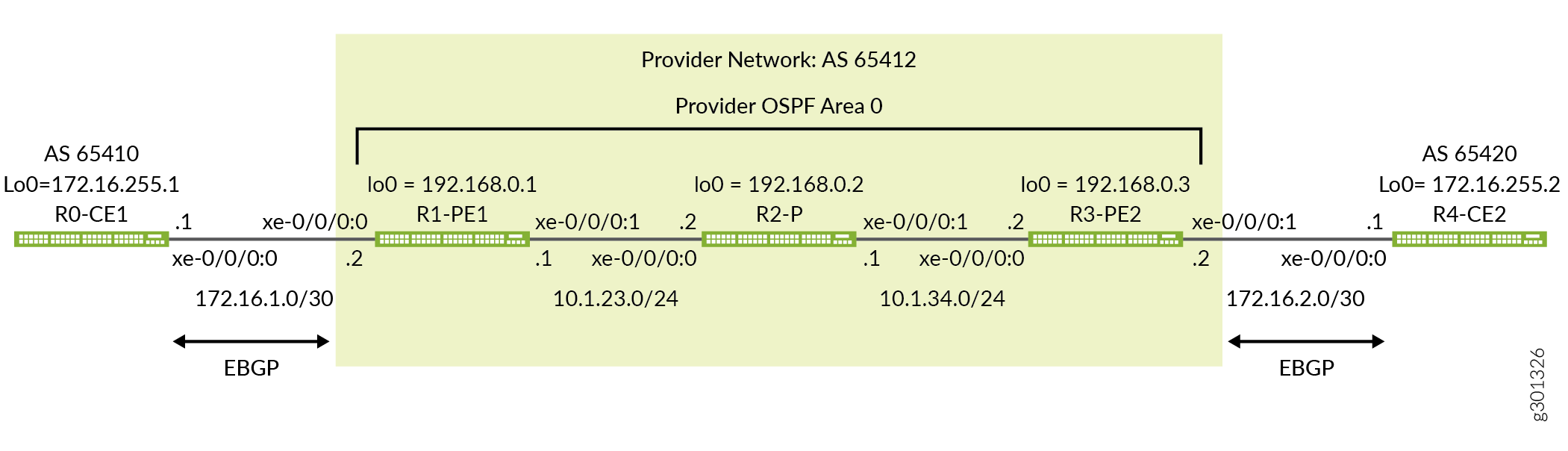
Figure 7 shows the topology used in this example. The figure details the interface names, IP addressing, and routing protocols used in the provider and customer networks. It also highlights the peering relationship between the CE and PE devices. In this example you expect each CE device to form an EBGP peering session to the local PE device. Note that the provider network and both customer sites have an assigned autonomous system number to support BGP operation. In this example routing policy is applied at the CE devices to have them advertise the direct routes for their provider facing and loopback interfaces.
Quick Configurations
Use the configurations in this section to quickly get your MPLS-based Layer 3 VPN up and running. The configurations include a functional MPLS baseline to support your Layer 3 VPN. This example focuses on the VPN aspects of the configuration. Refer to the following links for additional information on the baseline MPLS functionality used in this example:
CLI Quick Configuration
The device configurations omit the management interface, static routes, system logging, system services, and user login information. These parts of the configuration vary by location and are not directly related to MPLS or VPN functionality.
Edit the following commands as needed for the specifics of your environment and paste them into the local CE (CE1) device terminal window when in configuration mode at the [edit] hierarchy:
The complete configuration for the CE1 device.
set system host-name ce1
set interfaces xe-0/0/0:0 description "Link from CE1 to PE1 for L3vpn"
set interfaces xe-0/0/0:0 unit 0 family inet address 172.16.1.1/30
set interfaces lo0 unit 0 family inet address 172.16.255.1/32
set routing-options router-id 172.16.255.1
set routing-options autonomous-system 65410
set protocols bgp group PE1 type external
set protocols bgp group PE1 export adv_direct
set protocols bgp group PE1 peer-as 65412
set protocols bgp group PE1 neighbor 172.16.1.2
set policy-options policy-statement adv_direct term 1 from protocol direct
set policy-options policy-statement adv_direct term 1 from route-filter 172.16.0.0/16 orlonger
set policy-options policy-statement adv_direct term 1 then accept
The complete configuration for PE1 device.
set system host-name pe1
set interfaces xe-0/0/0:0 description "Link from PE1 to CE1 for L3vpn"
set interfaces xe-0/0/0:0 unit 0 family inet address 172.16.1.2/30
set interfaces xe-0/0/0:1 description "Link from PE1 to p-router"
set interfaces xe-0/0/0:1 mtu 4000
set interfaces xe-0/0/0:1 unit 0 family inet address 10.1.23.1/24
set interfaces xe-0/0/0:1 unit 0 family mpls
set interfaces lo0 unit 0 family inet address 192.168.0.1/32
set routing-instances CE1_L3vpn protocols bgp group CE1 type external
set routing-instances CE1_L3vpn protocols bgp group CE1 peer-as 65410
set routing-instances CE1_L3vpn protocols bgp group CE1 neighbor 172.16.1.1
set routing-instances CE1_L3vpn instance-type vrf
set routing-instances CE1_L3vpn interface xe-0/0/0:0.0
set routing-instances CE1_L3vpn route-distinguisher 192.168.0.1:12
set routing-instances CE1_L3vpn vrf-target target:65412:12
set routing-options router-id 192.168.0.1
set routing-options autonomous-system 65412
set protocols bgp group ibgp type internal
set protocols bgp group ibgp local-address 192.168.0.1
set protocols bgp group ibgp family inet-vpn unicast
set protocols bgp group ibgp neighbor 192.168.0.3
set protocols mpls label-switched-path lsp_to_pe2 to 192.168.0.3
set protocols mpls interface xe-0/0/0:1.0
set protocols ospf traffic-engineering
set protocols ospf area 0.0.0.0 interface lo0.0 passive
set protocols ospf area 0.0.0.0 interface xe-0/0/0:1.0
set protocols rsvp interface lo0.0
set protocols rsvp interface xe-0/0/0:1.0
The complete configuration for the P device.
set system host-name p
set interfaces xe-0/0/0:0 description "Link from p-router to PE1"
set interfaces xe-0/0/0:0 mtu 4000
set interfaces xe-0/0/0:0 unit 0 family inet address 10.1.23.2/24
set interfaces xe-0/0/0:0 unit 0 family mpls
set interfaces xe-0/0/0:1 description "Link from p-router to PE2"
set interfaces xe-0/0/0:1 mtu 4000
set interfaces xe-0/0/0:1 unit 0 family inet address 10.1.34.1/24
set interfaces xe-0/0/0:1 unit 0 family mpls
set interfaces lo0 unit 0 family inet address 192.168.0.2/32
set protocols mpls interface xe-0/0/0:0.0
set protocols mpls interface xe-0/0/0:1.0
set protocols ospf traffic-engineering
set protocols ospf area 0.0.0.0 interface lo0.0 passive
set protocols ospf area 0.0.0.0 interface xe-0/0/0:0.0
set protocols ospf area 0.0.0.0 interface xe-0/0/0:1.0
set protocols rsvp interface lo0.0
set protocols rsvp interface xe-0/0/0:0.0
set protocols rsvp interface xe-0/0/0:1.0
The complete configuration for the PE2 device.
set system host-name pe2
set interfaces xe-0/0/0:1 description "Link from PE2 to CE2 for L3vpn"
set interfaces xe-0/0/0:1 unit 0 family inet address 172.16.2.2/30
set interfaces xe-0/0/0:0 description "Link from PE2 to p-router"
set interfaces xe-0/0/0:0 mtu 4000
set interfaces xe-0/0/0:0 unit 0 family inet address 10.1.34.2/24
set interfaces xe-0/0/0:0 unit 0 family mpls
set interfaces lo0 unit 0 family inet address 192.168.0.3/32
set routing-instances CE2_L3vpn protocols bgp group CE2 type external
set routing-instances CE2_L3vpn protocols bgp group CE2 peer-as 65420
set routing-instances CE2_L3vpn protocols bgp group CE2 neighbor 172.16.2.1
set routing-instances CE2_L3vpn instance-type vrf
set routing-instances CE2_L3vpn interface xe-0/0/0:1.0
set routing-instances CE2_L3vpn route-distinguisher 192.168.0.3:12
set routing-instances CE2_L3vpn vrf-target target:65412:12
set routing-options router-id 192.168.0.3
set routing-options autonomous-system 65412
set protocols bgp group ibgp type internal
set protocols bgp group ibgp local-address 192.168.0.3
set protocols bgp group ibgp family inet-vpn unicast
set protocols bgp group ibgp neighbor 192.168.0.1
set protocols mpls label-switched-path lsp_to_pe1 to 192.168.0.1
set protocols mpls interface xe-0/0/0:0.0
set protocols ospf traffic-engineering
set protocols ospf area 0.0.0.0 interface lo0.0 passive
set protocols ospf area 0.0.0.0 interface xe-0/0/0:0.0
set protocols rsvp interface lo0.0
set protocols rsvp interface xe-0/0/0:0.0
The complete configuration for the CE2 device.
set system host-name ce2
set interfaces xe-0/0/0:0 description "Link from CE2 to PE2 for L3vpn"
set interfaces xe-0/0/0:0 unit 0 family inet address 172.16.2.1/30
set interfaces lo0 unit 0 family inet address 172.16.255.2/32
set routing-options router-id 172.16.255.2
set routing-options autonomous-system 65420
set protocols bgp group PE2 type external
set protocols bgp group PE2 export adv_direct
set protocols bgp group PE2 peer-as 65412
set protocols bgp group PE2 neighbor 172.16.2.2
set policy-options policy-statement adv_direct term 1 from protocol direct
set policy-options policy-statement adv_direct term 1 from route-filter 172.16.0.0/16 orlonger
set policy-options policy-statement adv_direct term 1 then accept
Be sure to commit the configuration changes on all devices when satisfied with your work. Congratulations on your new MPLS-based Layer 3 VPN! Refer to the Verification section for the steps needed to confirm your Layer 3 VPN is working as expected.
Configure the Local PE (PE1) Device for a MPLS-Based Layer 3 VPN
This section covers the steps needed to configure the PE1 device for this example. The focus in on the PE devices because that is where the VPN configuration is housed. Refer to the Quick Configurations section for the CE device and P device configurations used in this example.
Configure the MPLS Baseline (if needed)
Before you configure a Layer 3 VPN make sure the PE device has a working MPLS baseline. If you already having an MPLS baseline you can skip to the step-by-step procedure to add the Layer 3 VPN to the PE devices.
Configure the hostname.
[edit]
user@pe1# set system host-name pe1
Configure the core and loopback interfaces:
[edit]
user@pe1# set interfaces xe-0/0/0:1 description "Link from PE1 to P-router"
[edit]
user@pe1# set interfaces xe-0/0/0:1 mtu 4000
[edit]
user@pe1# set interfaces xe-0/0/0:1 unit 0 family inet address 10.1.23.1/24
[edit]
user@pe1# set interfaces xe-0/0/0:1 unit 0 family mpls
[edit]
user@pe1# set interfaces lo0 unit 0 family inet address 192.168.0.1/32
Best Practice:While a Layer 3 VPN can perform fragmentation at the ingress PE, its best practice to design the network so the CE can send a maximum sized frame without needing fragmentation. To ensure fragmentation does not occur the provider network should support the largest frame that the CE devices can generate after the MPLS and virtual routing and forwarding (VRF) labels are added by the PE device. This example leaves the CE devices at the default 1500-byte maximum transmission unit (MTU) while configuring the provider core to support a 4000 byte MTU. This ensures the CE devices cannot exceed the MTU in the provider's network even with the MPLS and VRF encapsulation overhead.
Configure the protocols:
Note:Traffic engineering is supported for RSVP-signaled LSPs but is not required for basic MPLS switching or VPN deployment. The provided MPLS baseline uses RSVP to signal LSPs, and enables traffic engineering for OSPF. However, no path constraints are configured so you expect the LSPs to be routed over the interior gateway protocol's shortest path.
[edit]
user@pe1# set protocols ospf area 0.0.0.0 interface lo0.0 passive
[edit]
user@pe1# set protocols ospf area 0.0.0.0 interface xe-0/0/0:1.0
[edit]
user@pe1# set protocols ospf traffic-engineering
[edit]
user@pe1# set protocols mpls interface xe-0/0/0:1.0
[edit]
user@pe1# set protocols rsvp interface lo0.0
[edit]
user@pe1# set protocols rsvp interface xe-0/0/0:1.0
Define the LSP to the remote PE device's loopback address:
[edit]
user@pe1#  set protocols mpls label-switched-path lsp_to_pe2 to 192.168.0.3
The MPLS baseline is now configured on the PE1 device. Keep going to configure the Layer 3 VPN.
Procedure
Step-by-Step Procedure
Follow these steps to configure the PE1 device for a Layer 3 VPN.
Configure the customer-facing interface:
Tip:You can configure both an MPLS-based Layer 2 VPN and an MPLS-based Layer 3 VPN on the same PE device. However, you cannot configure the same customer edge-facing interface to support both a Layer 2 VPN and a Layer 3 VPN.
[edit interfaces]
user@pe1# set xe-0/0/0:0 description "Link from PE1 to CE1 for L3vpn"
[edit]
user@pe1# set xe-0/0/0:0 unit 0 family inet address 172.16.1.2/30
Configure a BGP group for the peering between the local and remote PE devices. Use the PE device’s loopback address as the local address, and enable the
inet-vpn unicastaddress family to support Layer 3 VPN route exchange. A routing policy for BGP is not needed on the PE devices in this example. By default the PE devices readvertise into IBGP the routes they learn over their EBGP peering to the CE device.[edit protocols bgp] user@pe1# set group ibgp local-address 192.168.0.1 [edit protocols bgp] user@pe1# set group ibgp family inet-vpn unicast
Tip:You can specify other address families if the PE to PE IBGP session needs to support non-VPN route exchange, such as regular IPv4 or IPv6 routes using the
inetorinet6families, respectively.Configure the BGP group type as internal.
[edit protocols bgp]
user@pe1# set group ibgp type internal
Configure the remote PE device’s loopback address as a BGP neighbor.
[edit protocols bgp]
user@pe1# set group ibgp neighbor 192.168.0.3
Configure the router ID to match its loopback address, and define the BGP autonomous system number needed for BGP peering.
[edit routing-options]
user@pe1# set router-id 192.168.0.1
[edit routing-options]
user@pe1# set autonomous-system 65412
Configure the routing instance. Specify an instance name of CE1_L3vpn, and configure an
instance-typeofvrf.[edit routing-instances] user@pe1# set CE1_L3vpn instance-type vrf
Configure the PE device’s customer-facing interface to belong to the routing instance.
[edit routing-instances]
user@pe1# set CE1_L3vpn interface xe-0/0/0:0.0
Configure the routing instance’s route distinguisher. This setting is used to distinguish the routes sent from a particular VRF on a particular PE device. It should be unique for each routing instance on each PE device.
[edit routing-instances]
user@pe1# set CE1_L3vpn route-distinguisher 192.168.0.1:12
Configure the instance’s virtual routing and forwarding (VRF) table route target. The
vrf-targetstatement adds the specified community tag to all advertised routes while automatically matching the same value for route import. Configuring matching route targets on the PE devices that share a given VPN is required for proper route exchange.[edit routing-instances] user@pe1# set CE1_L3vpn vrf-target target:65142:12
Note:You can create more complex policies by explicitly configuring VRF import and export policies using the import and export options. See vrf-import and vrf-export for details.
Configure the routing instance to support EBGP peering to the CE1 device. Direct interface peering to the CE1 end of the VRF link is used, and CE1’s autonomous system number is correctly specified with the
peer-asparameter.[edit routing-instances] user@pe1# set CE1_L3vpn protocols bgp group CE1 type external [edit routing-instances] user@pe1# set CE1_L3vpn protocols bgp group CE1 peer-as 65410 [edit routing-instances] user@pe1# set CE1_L3vpn protocols bgp group CE1 neighbor 172.16.1.1
Commit your changes at the PE1 device and return to CLI operational mode.
[edit]
user@pe1# commit and-quit
Results
Display the results of the configuration on the PE1 device. The output reflects only the functional configuration added in this example.
user@pe1> show configuration
interfaces {
    xe-0/0/0:0 {
        description "Link from PE1 to CE1 for L3vpn";
        unit 0 {
            family inet {
                address 172.16.1.2/30;
            }
        }
    }
    xe-0/0/0:1 {
        description "Link from PE1 to p-router";
        mtu 4000;
        unit 0 {
            family inet {
                address 10.1.23.1/24;
            }
            family mpls;
        }
    }
    lo0 {
        unit 0 {
            family inet {
                address 192.168.0.1/32;
            }
        }
    }
}

routing-instances {
    CE1_L3vpn {
        protocols {
            bgp {
                group CE1 {
                    type external;
                    peer-as 65410;
                    neighbor 172.16.1.1;
                }
            }
        }
        instance-type vrf;
        interface xe-0/0/0:0.0;
        route-distinguisher 192.168.0.1:12;
        vrf-target target:65412:12;
    }
}
routing-options {
    router-id 192.168.0.1;
    autonomous-system 65412;
}
protocols {
    bgp {
        group ibgp {
            type internal;
            local-address 192.168.0.1;
            family inet-vpn {
                unicast;
            }
            neighbor 192.168.0.3;
        }
    }
    mpls {
        label-switched-path lsp_to_pe2 {
            to 192.168.0.3;
        }
        interface xe-0/0/0:1.0;
    }
    ospf {
        traffic-engineering;
        area 0.0.0.0 {
            interface lo0.0 {
                passive;
            }
            interface xe-0/0/0:1.0;
        }
    }
    rsvp {
        interface lo0.0;
        interface xe-0/0/0:1.0;
    }
}
Configure the Remote PE (PE2) Device for a MPLS-Based Layer 3 VPN
This section covers the steps needed to configure the PE1 device for this example. The focus in on the PE devices because that is where the VPN configuration is housed. Refer to the Quick Configurations section for the CE device and P device configurations used in this example.
Configure the MPLS Baseline (if needed)
Before you configure a Layer 3 VPN make sure the PE device has a working MPLS baseline. If you already having an MPLS baseline you can skip to the step-by-step procedure to add the Layer 3 VPN to the PE devices.
Configure the hostname.
[edit]
user@pe2# set system host-name pe2
Configure the core and loopback interfaces:
[edit]
user@pe2# set interfaces xe-0/0/0:0 description "Link from PE2 to P-router"
[edit]
user@pe2# set interfaces xe-0/0/0:0 mtu 4000
[edit]
user@pe2# set interfaces xe-0/0/0:0 unit 0 family inet address 10.1.34.2/24
[edit]
user@pe2# set interfaces xe-0/0/0:0 unit 0 family mpls
[edit]
user@pe2# set interfaces lo0 unit 0 family inet address 192.168.0.3/32
Best Practice:While a Layer 3 VPN can perform fragmentation at the ingress PE, its best practice to design the network so the CE can send a maximum sized frame without needing fragmentation. To ensure fragmentation does not occur the provider network should support the largest frame that the CE devices can generate after the MPLS and virtual routing and forwarding (VRF) labels are added by the PE device. This example leaves the CE devices at the default 1500-byte maximum transmission unit (MTU) while configuring the provider core to support a 4000 byte MTU. This ensures the CE devices cannot exceed the MTU in the provider's network even with the MPLS and VRF encapsulation overhead.
Configure the protocols:
Note:Traffic engineering is supported for RSVP-signaled LSPs but is not required for basic MPLS switching or VPN deployment. The provided MPLS baseline uses RSVP to signal LSPs, and enables traffic engineering for OSPF. However, no path constraints are configured so you expect the LSPs to be routed over the interior gateway protocol's shortest path.
[edit]
user@pe2# set protocols ospf area 0.0.0.0 interface lo0.0 passive
[edit]
user@pe2# set protocols ospf area 0.0.0.0 interface xe-0/0/0:0.0
[edit]
user@pe2# set protocols ospf traffic-engineering
[edit]
user@pe2# set protocols mpls interface xe-0/0/0:0.0
[edit]
user@pe2# set protocols rsvp interface lo0.0
[edit]
user@pe2# set protocols rsvp interface xe-0/0/0:0.0
Define the LSP to the remote PE device's loopback address:
[edit]
user@pe2# set protocols mpls label-switched-path lsp_to_pe1 to 192.168.0.1
The MPLS baseline is now configured on the PE1 device. Keep going to configure the Layer 3 VPN.
Procedure
Step-by-Step Procedure
Follow these steps to configure the PE2 device for a Layer 3 VPN.
Configure the customer-facing interface:
Tip:You can configure both an MPLS-based Layer 2 VPN and an MPLS-based Layer 3 VPN on the same PE device. However, you cannot configure the same customer edge-facing interface to support both a Layer 2 VPN and a Layer 3 VPN.
[edit interfaces]
user@pe2# set xe-0/0/0:1 description "Link from PE2 to CE2 for L3vpn"
[edit]
user@pe2# set xe-0/0/0:1 unit 0 family inet address 172.16.2.2/30
Configure a BGP group for the peering between the local and remote PE devices. Use the PE device’s loopback address as the local address, and enable the
inet-vpn unicastaddress family to support Layer 3 VPN route exchange.[edit protocols bgp] user@pe1# set group ibgp local-address 192.168.0.1 [edit protocols bgp] user@pe1# set group ibgp family inet-vpn unicast
Tip:You can specify other address families if the PE to PE IBGP session needs to support non-VPN route exchange, such as regular IPv4 or IPv6 routes using the
inetorinet6families, respectively.Configure the BGP group type as internal.
[edit protocols bgp]
user@pe2# set group ibgp type internal
Configure the PE1 device’s loopback address as a BGP neighbor.
[edit protocols bgp]
user@pe2# set group ibgp neighbor 192.168.0.1
Configure the router ID to match its loopback address, and define the BGP autonomous system number.
[edit routing-options]
user@pe2# set routing-options router-id 192.168.0.3
[edit routing-options]
user@pe2# set autonomous-system 65412
Configure the routing instance. Specify an instance name of CE2_L3vpn, with an
instance-typeofvrf.[edit routing-instances] user@pe2# set CE2_L3vpn instance-type vrf
Configure the PE device’s customer-facing interface to belong to the routing instance.
[edit routing-instances]
user@pe2# set CE2_L3vpn interface xe-0/0/0:1.0
Configure the routing instance’s route distinguisher. This setting is used to distinguish the routes sent from a particular VRF on a particular PE device. It should be unique for each routing instance on each PE device.
[edit routing-instances]
user@pe2# set CE2_L3vpn route-distinguisher 192.168.0.3:12
Configure the instance’s virtual routing and forwarding (VRF) table route target. The
vrf-targetstatement adds the specified community tag to all advertised routes while automatically matching the same value for route import. Configuring matching route targets on the PE devices that share a given VPN is required for proper route exchange.[edit routing-instances] user@pe2# set CE2_L3vpn vrf-target target:65412:12
Note:You can create more complex policies by explicitly configuring VRF import and export policies using the import and export options. See vrf-import and vrf-export for details.
Configure the routing instance to support EBGP peering to the CE2 device. Direct interface peering to the CE2 end of the VRF link is used, and CE2’s autonomous system number is correctly specified with the
peer-asparameter.[edit routing-instances] user@pe2# set CE2_L3vpn protocols bgp group CE2 type external [edit routing-instances] user@pe2# set CE2_L3vpn protocols bgp group CE2 peer-as 65420 [edit routing-instances] user@pe2# set CE2_L3vpn protocols bgp group CE2 neighbor 172.16.2.1
Commit your changes at the PE2 device and return to CLI operational mode.
[edit]
user@pe2# commit and-quit
Results
Display the results of the configuration on the PE2 device. The output reflects only the functional configuration added in this example.
user@pe2> show configuration
interfaces {
    xe-0/0/0:0 {
        description "Link from PE2 to p-router";
        mtu 4000;
        unit 0 {
            family inet {
                address 10.1.34.2/24;
            }
            family mpls;
        }
    }
    xe-0/0/0:1 {
        description "Link from PE2 to CE2 for L3vpn";
        unit 0 {
            family inet {
                address 172.16.2.2/30;
            }
        }
    }
    lo0 {
        unit 0 {
            family inet {
                address 192.168.0.3/32;
            }
        }
    }
}
routing-instances {
    CE2_L3vpn {
        protocols {
            bgp {
                group CE2 {
                    type external;
                    peer-as 65420;
                    neighbor 172.16.2.1;
                }
            }
        }
        instance-type vrf;
        interface xe-0/0/0:1.0;
        route-distinguisher 192.168.0.3:12;
        vrf-target target:65412:12;
    }
}
routing-options {
    router-id 192.168.0.3;
    autonomous-system 65412;
}
protocols {
    bgp {
        group ibgp {
            type internal;
            local-address 192.168.0.3;
            family inet-vpn {
                unicast;
            }
            neighbor 192.168.0.1;
        }
    }
    mpls {
        label-switched-path lsp_to_pe1 {
            to 192.168.0.1;
        }
        interface xe-0/0/0:0.0;
    }
    ospf {
        traffic-engineering;
        area 0.0.0.0 {
            interface lo0.0 {
                passive;
            }
            interface xe-0/0/0:0.0;
        }
    }
    rsvp {
        interface lo0.0;
        interface xe-0/0/0:0.0;
    }
}
Verification
Perform these tasks to verify that the MPLS-based Layer 3 VPN works properly:
- Verify Provider OSPF Adjacencies and Route Exchange
- Verify MPLS and RSVP Interface Settings
- Verify RSVP Signaled LSPs
- Verify BGP Session Status
- Verify Layer 3 VPN Routes in the Routing Table
- Ping the Remote PE Device Using the Layer 3 VPN Connection
- Verify End-to-End Operation of the CE Devices Over the Layer 3 VPN
- Platform-Specific MPLS Layer 3 VPN Behavior
Verify Provider OSPF Adjacencies and Route Exchange
Purpose
Confirm the OSPF protocol is working properly in the provider network by verifying adjacency status and OSPF learned routes to the loopback addresses of the remote provider devices. Proper IGP operation is critical for the successful establishment of MPLS LSPs.
Action
user@pe1> show ospf neighbor

Address          Interface              State           ID               Pri  Dead
10.1.23.2        xe-0/0/0:1.0           Full            192.168.0.2      128    37
user@pe1> show route protocol ospf | match 192.168

192.168.0.2/32     *[OSPF/10] 1w1d 23:59:43, metric 1
192.168.0.3/32     *[OSPF/10] 1w1d 23:59:38, metric 2
Meaning
The output shows that the PE1 device has established an OSPF adjacency to the
P device (192.168.0.2). It also shows that the P and remote
PE device loopback addresses (192.168.0.2) and
(192.168.0.3) are correctly learned via OSPF at the
local PE device.
Verify MPLS and RSVP Interface Settings
Purpose
Verify that the RSVP and MPLS protocols are configured to operate on the PE
device’s core-facing interface. This step also verifies that family
mpls is correctly configured at the unit level of the PE
device’s core-facing interface.
Action
user@pe1> show mpls interface

Interface        State       Administrative groups (x: extended)
xe-0/0/0:1.0     Up         <none>
user@pe1> show rsvp interface

RSVP interface: 2 active
                          Active  Subscr- Static      Available   Reserved    Highwater
Interface          State  resv    iption  BW          BW          BW          mark
lo0.0                  Up       0   100%  0bps        0bps        0bps        0bps
xe-0/0/0:1.0           Up       1   100%  10Gbps      10Gbps      0bps        0bps
Meaning
The output shows that MPLS and RSVP are correctly configured on the local PE device’s core and loopback interfaces.
Verify RSVP Signaled LSPs
Purpose
Verify that RSVP signaled ingress and egress LSPs are correctly established between the PE device’s loopback addresses.
Action
user@pe1> show rsvp session

Ingress RSVP: 1 sessions
To              From            State   Rt Style Labelin Labelout LSPname
192.168.0.3     192.168.0.1     Up       0  1 FF       -       17 lsp_to_pe2
Total 1 displayed, Up 1, Down 0

Egress RSVP: 1 sessions
To              From            State   Rt Style Labelin Labelout LSPname
192.168.0.1     192.168.0.3     Up       0  1 FF       3        - lsp_to_pe1
Total 1 displayed, Up 1, Down 0

Transit RSVP: 0 sessions
Total 0 displayed, Up 0, Down 0
Meaning
The output shows that both the ingress and egress RSVP sessions are correctly established between the PE devices. Successful LSP establishment indicates the MPLS baseline is operational.
Verify BGP Session Status
Purpose
Verify that the IBGP session between the PE devices is correctly established with support for Layer 3 VPN network layer reachability information (NLRI). In this step you also confirm the local PE to CE EBGP session is established and correctly configured to exchange IPv4 routes.
Action
user@pe1> show bgp summary

Groups: 2 Peers: 2 Down peers: 0
Table          Tot Paths  Act Paths Suppressed    History Damp State    Pending
inet.0
                       0          0          0          0          0          0
bgp.l3vpn.0
                       2          2          0          0          0          0
Peer                     AS      InPkt     OutPkt    OutQ   Flaps Last Up/Dwn State|#Active/Received/Accepted/Damped...
172.16.1.1            65410      26038      25938       0       0 1w1d 3:12:32 Establ
  CE1_L3vpn.inet.0: 1/2/2/0
192.168.0.3           65412         19         17       0       0        6:18 Establ
  CE1_L3vpn.inet.0: 2/2/2/0
  bgp.l3vpn.0: 2/2/2/0
Meaning
The output shows the IBGP session to the remote PE device
(192.168.0.3) has been correctly established
(Establ), and through the Up/Dwn
field, how long the session has been in the current state
(6:18). The flaps field confirms that
no state transitions have occurred (0), indicating the
session is stable. Also note that Layer 3 VPN routes (NLRI) have been
learned from the remote PE as shown by the presence of a
bgp.l3vpn.0 table.
The display also confirms the EBGP session to the local CE1 device
(172.16.1.1) is established and that IPv4 routes have
been received from the CE1 device and installed in the CE1 device routing
instance (CE1_L3vpn.inet.0)
This output confirms that the BGP peering between the PE devices, and to the CE device, is working properly to support your Layer 3 VPN.
Verify Layer 3 VPN Routes in the Routing Table
Purpose
Confirm that the routing table on the PE1 device is populated with Layer 3 VPN routes advertised by the remote PE. These routes are used to forward traffic to the remote CE device.
Action
user@pe1> show route table bgp.l3vpn.0

bgp.l3vpn.0: 2 destinations, 2 routes (2 active, 0 holddown, 0 hidden)
+ = Active Route, - = Last Active, * = Both

192.168.0.3:12:172.16.2.0/30
                   *[BGP/170] 00:22:45, localpref 100, from 192.168.0.3
                      AS path: I, validation-state: unverified
                    >  to 10.1.23.2 via xe-0/0/0:1.0, label-switched-path lsp_to_pe2
192.168.0.3:12:172.16.255.2/32
                   *[BGP/170] 00:22:43, localpref 100, from 192.168.0.3
                      AS path: 65420 I, validation-state: unverified
> to 10.1.23.2 via xe-0/0/0:1.0, label-switched-path lsp_to_pe2user@pe1> show route table CE1_L3vpn.inet.0
CE1_L3vpn.inet.0: 5 destinations, 6 routes (5 active, 0 holddown, 0 hidden)
+ = Active Route, - = Last Active, * = Both
172.16.1.0/30 *[Direct/0] 1w1d 03:29:44
> via xe-0/0/0:0.0
[BGP/170] 1w1d 03:29:41, localpref 100
AS path: 65410 I, validation-state: unverified
> to 172.16.1.1 via xe-0/0/0:0.0
172.16.1.2/32 *[Local/0] 1w1d 03:29:44
Local via xe-0/0/0:0.0
172.16.2.0/30 *[BGP/170] 00:23:28, localpref 100, from 192.168.0.3
AS path: I, validation-state: unverified
> to 10.1.23.2 via xe-0/0/0:1.0, label-switched-path lsp_to_pe2
172.16.255.1/32 *[BGP/170] 1w1d 03:29:41, localpref 100
AS path: 65410 I, validation-state: unverified
> to 172.16.1.1 via xe-0/0/0:0.0
172.16.255.2/32 *[BGP/170] 00:23:26, localpref 100, from 192.168.0.3
AS path: 65420 I, validation-state: unverified
> to 10.1.23.2 via xe-0/0/0:1.0, label-switched-path lsp_to_pe2
Meaning
The show route table bgp.l3vpn.0 command displays the Layer
3 VPN routes that have been received from the remote PE device. The
show route table CE1_L3vpn.inet.0 command lists the all
routes that have been imported into the CE1_L3vpn routing
instance. These entries represent the routes learned from the local EBGP
peering to the CE1 device, in addition to those routes received from the
remote PE2 device with a matching route target.
Both tables show the remote Layer 3 VPN routes are correctly associated with
the lsp_to_pe2 LSP as a forwarding next hop. The outputs
confirm the local PE device has learned the routes associated with the
remote CE2 location from the PE2 device. It also shows that the local PE
will forward Layer 3 VPN traffic to the remote PE2 device using MPLS
transport over the provider network.
Ping the Remote PE Device Using the Layer 3 VPN Connection
Purpose
Verify Layer 3 VPN connectivity between the local and remote PE devices using ping. This command verifies the Layer 3 VPN routing and MPLS forwarding operation between the PE devices.
Action
user@pe1> ping routing-instance CE1_L3vpn 172.16.2.2 source 172.16.1.2 count 2

PING 172.16.2.2 (172.16.2.2): 56 data bytes
64 bytes from 172.16.2.2: icmp_seq=0 ttl=61 time=128.235 ms
64 bytes from 172.16.2.2: icmp_seq=1 ttl=61 time=87.597 ms

--- 172.16.2.2 ping statistics ---
2 packets transmitted, 2 packets received, 0% packet loss
round-trip min/avg/max/stddev = 87.597/107.916/128.235/20.319 m
Meaning
The output confirms that the Layer 3 VPN control and forwarding planes are operating correctly between the PE devices.
Verify End-to-End Operation of the CE Devices Over the Layer 3 VPN
Purpose
Verify Layer 3 VPN connectivity between the CE devices. This step confirms the CE devices have operational interfaces and are properly configured for EBGP based Layer 3 connectivity. This is done by verifying the local CE1 device has learned the remote CE device’s routes, and by confirming the CE devices are able to pass traffic end-to-end between their loopback addresses.
Action
user@ce1> show route protocol bgp

inet.0: 12 destinations, 12 routes (12 active, 0 holddown, 0 hidden)
+ = Active Route, - = Last Active, * = Both

172.16.2.0/30      *[BGP/170] 00:40:50, localpref 100
                      AS path: 65412 I, validation-state: unverified
                    >  to 172.16.1.2 via xe-0/0/0:0.0
172.16.255.2/32    *[BGP/170] 00:40:49, localpref 100
                      AS path: 65412 65420 I, validation-state: unverified
                    >  to 172.16.1.2 via xe-0/0/0:0.0

inet6.0: 1 destinations, 1 routes (1 active, 0 holddown, 0 hidden)user@ce1> ping 172.16.255.2 source 172.16.255.1 size 1472 do-not-fragment count 2 PING 172.16.255.2 (172.16.255.2): 1472 data bytes 1480 bytes from 172.16.255.2: icmp_seq=0 ttl=61 time=79.245 ms 1480 bytes from 172.16.255.2: icmp_seq=1 ttl=61 time=89.125 ms --- 172.16.255.2 ping statistics --- 2 packets transmitted, 2 packets received, 0% packet loss round-trip min/avg/max/stddev = 79.245/84.185/89.125/4.940 ms
Meaning
The output shows that Layer 3 VPN based connectivity is working correctly
between the CE devices. The local CE device has learned the remote CE
device’s VRF interface and loopback routes through BGP. The ping is
generated to the loopback address of the remote CE device, and is sourced
from the local CE device’s loopback address using the source
172.16.255.1 argument. Adding the
do-not-fragment and size 1472 switches
confirms that the CE devices are able to pass 1500-byte IP packets without
evoking fragmentation in the local PE device.
The size 1472 argument added to the
ping command generates 1472 bytes of echo data. An
additional 8 bytes of Internet Control Message Protocol (ICMP) and 20
bytes of IP header are added to bring the total payload size to
1500-bytes. Adding the do-not-fragment switch ensures
that the local CE and PE devices cannot perform fragmentation. This ping
method confirms that fragmentation is not needed when exchanging
standard 1500-byte maximum length Ethernet frames between the CE
devices.
These results confirm the MPLS-based Layer 3 VPN is working correctly.
Platform-Specific MPLS Layer 3 VPN Behavior
Use Feature Explorer to confirm platform and release support for specific features.
Use the following table to review platform-specific behaviors for your platform.
|
Platform |
Difference |
|---|---|
|
ACX 7000 Series Routers |
|