Distributing VPN Routes
This topic describes configuring a router to handle route information in BGP, MPLS signaling, and policies.
Enabling Routing Information Exchange for VPNs
For Layer 2 VPNs, Layer 3 VPNs, virtual-router routing
instances, VPLS, EVPNs, and Layer 2 circuits to function properly,
the service provider’s PE and P routers must be able to exchange
routing information. For this to happen, you must configure either
an IGP (such as OSPF or IS-IS) or static routes on these routers.
You configure the IGP on the master instance of the routing protocol
process at the [edit protocols] hierarchy level, not
within the routing instance used for the VPN—that is, not at
the [edit routing-instances] hierarchy level.
When you configure the PE router, do not configure any summarization of the PE router’s loopback addresses at the area boundary. Each PE router’s loopback address should appear as a separate route.
Configuring IBGP Sessions Between PE Routers in VPNs
You must configure an IBGP session between the PE routers to allow the PE routers to exchange information about routes originating and terminating in the VPN. The PE routers rely on this information to determine which labels to use for traffic destined for remote sites.
Configure an IBGP session for the VPN as follows:
[edit protocols]
bgp {
    group group-name {
        type internal;
        local-address ip-address;
        family evpn {
            signaling;
        }
        family (inet-vpn | inet6-vpn) {
            unicast;
        }
        family l2vpn {
            signaling;
        }
        neighbor ip-address;
    }
}
The IP address in the local-address statement is
the address of the loopback interface on the local PE router. The
IBGP session for the VPN runs through the loopback address. (You must
also configure the loopback interface at the [edit interfaces] hierarchy level.)
The IP address in the neighbor statement is the loopback
address of the neighboring PE router. If you are using RSVP signaling,
this IP address is the same address you specify in the to statement at the [edit mpls label-switched-path lsp-path-name] hierarchy level when you configure the MPLS LSP.
The family statement allows you to configure
the IBGP session for Layer 2 VPNs, VPLS, EVPNs or for Layer 3
VPNs.
To configure an IBGP session for Layer 2 VPNs and VPLS, include the
signalingstatement at the[edit protocols bgp group group-name family l2vpn]hierarchy level:[edit protocols bgp group group-name family l2vpn] signaling;
To configure an IBGP session for EVPNs, include the
signalingstatement at the[edit protocols bgp group group-name family evpn]hierarchy level:[edit protocols bgp group group-name family evpn] signaling;
To configure an IPv4 IBGP session for Layer 3 VPNs, configure the
unicaststatement at the[edit protocols bgp group group-name family inet-vpn]hierarchy level:[edit protocols bgp group group-name family inet-vpn] unicast;
To configure an IPv6 IBGP session for Layer 3 VPNs, configure the
unicaststatement at the[edit protocols bgp group group-name family inet6-vpn]hierarchy level:[edit protocols bgp group group-name family inet6-vpn] unicast;
You can configure both family inet and family inet-vpn or both family inet6 and family
inet6-vpn within the same peer group. This allows you to enable
support for both IPv4 and IPv4 VPN routes or both IPv6 and IPv6 VPN
routes within the same peer group.
Configuring Aggregate Labels for VPNs
Aggregate labels for VPNs allow a Juniper Networks routing platform to aggregate a set of incoming labels (labels received from a peer router) into a single forwarding label that is selected from the set of incoming labels. The single forwarding label corresponds to a single next hop for that set of labels. Label aggregation reduces the number of VPN labels that the router must examine.
For a set of labels to share an aggregate forwarding label, they must belong to the same forwarding equivalence class (FEC). The labeled packets must have the same destination egress interface.
Including the community community-name statement with the aggregate-label statement lets
you specify prefixes with a common origin community. Set by policy
on the peer PE, these prefixes represent an FEC on the peer PE router.
If the target community is set by mistake instead of the origin community, forwarding problems at the egress PE can result. All prefixes from the peer PE will appear to be in the same FEC, resulting in a single inner label for all CE routers behind a given PE in the same VPN.
To work with route reflectors in Layer 3 VPN networks, the router aggregates a set of incoming labels only when the routes:
Are received from the same peer router
Have the same site of origin community
Have the same next hop
The next hop requirement is important because route reflectors forward routes originated from different BGP peers to another BGP peer without changing the next hop of those routes.
To configure aggregate labels for VPNs, include the aggregate-label statement:
aggregate-label {
    community community-name;
}
For a list of hierarchy levels at which you can include this statement, see the statement summary for this statement.
For information about how to configure a community, see Understanding BGP Communities, Extended Communities, and Large Communities as Routing Policy Match Conditions.
Configuring a Signaling Protocol and LSPs for VPNs
For VPNs to function, you must enable a signaling protocol, either the LDP or RSVP on the provider edge (PE) routers and on the provider (P) routers. You also need to configure label-switched paths (LSPs) between the ingress and egress routers. In a typical VPN configuration, you need to configure LSPs from each PE router to all of the other PE routers participating in the VPN in a full mesh.
To enable a signaling protocol, perform the steps in one of the following sections:
Using LDP for VPN Signaling
To use LDP for VPN signaling, perform the following steps on the PE and provider (P) routers:
Configure LDP on the interfaces in the core of the service provider’s network by including the
ldpstatement at the[edit protocols]hierarchy level.You need to configure LDP only on the interfaces between PE routers or between PE and P routers. You can think of these as the “core-facing” interfaces. You do not need to configure LDP on the interface between the PE and customer edge (CE) routers.
[edit]
protocols {
    ldp {
        interface type-fpc/pic/port;
    }
}
Configure the MPLS address family on the interfaces on which you enabled LDP (the interfaces you configured in Step 1) by including the
family mplsstatement at the[edit interfaces type-fpc/pic/port unit logical-unit-number]hierarchy level.[edit] interfaces { type-fpc/pic/port { unit logical-unit-number { family mpls; } } }Configure OSPF or IS-IS on each PE and P router.
You configure these protocols at the master instance of the routing protocol, not within the routing instance used for the VPN.
To configure OSPF, include the
ospfstatement at the[edit protocols]hierarchy level. At a minimum, you must configure a backbone area on at least one of the router’s interfaces.[edit] protocols { ospf { area 0.0.0.0 { interface type-fpc/pic/port; } } }To configure IS-IS, include the
isisstatement at the[edit protocols]hierarchy level and configure the loopback interface and International Organization for Standardization (ISO) family at the[edit interfaces]hierarchy level. At a minimum, you must enable IS-IS on the router, configure a network entity title (NET) on one of the router’s interfaces (preferably the loopback interface, lo0), and configure the ISO family on all interfaces on which you want IS-IS to run. When you enable IS-IS, Level 1 and Level 2 are enabled by default. The following is the minimum IS-IS configuration. In theaddressstatement,addressis the NET.[edit] interfaces { lo0 { unit logical-unit-number { family iso { address address; } } } type-fpc/pic/port { unit logical-unit-number { family iso; } } } protocols { isis { interface all; } }
Using RSVP for VPN Signaling
To use RSVP for VPN signaling, perform the following steps:
On each PE router, configure traffic engineering.
To do this, you must configure an interior gateway protocol (IGP) that supports traffic engineering (either IS-IS or OSPF) and enable traffic engineering support for that protocol.
To enable OSPF traffic engineering support, include the
traffic-engineeringstatement at the[edit protocols ospf]hierarchy level:[edit protocols ospf] traffic-engineering { shortcuts; }For IS-IS, traffic engineering support is enabled by default.
On each PE and P router, enable RSVP on the interfaces that participate in the label-switched path (LSP).
On the PE router, these interfaces are the ingress and egress points to the LSP. On the P router, these interfaces connect the LSP between the PE routers. Do not enable RSVP on the interface between the PE and the CE routers, because this interface is not part of the LSP.
To configure RSVP on the PE and P routers, include the
interfacestatement at the[edit protocols rsvp]hierarchy level. Include oneinterfacestatement for each interface on which you are enabling RSVP.[edit protocols] rsvp { interface interface-name; interface interface-name; }On each PE router, configure an MPLS LSP to the PE router that is the LSP’s egress point.
To do this, include the
interfaceandlabel-switched-pathstatements at the[edit protocols mpls]hierarchy level:[edit protocols] mpls { interface interface-name; label-switched-path path-name { to ip-address; } }In the
tostatement, specify the address of the LSP’s egress point, which is an address on the remote PE router.In the
interfacestatement, specify the name of the interface (both the physical and logical portions). Include oneinterfacestatement for the interface associated with the LSP.When you configure the logical portion of the same interface at the
[edit interfaces]hierarchy level, you must also configure thefamily inetandfamily mplsstatements:[edit interfaces] interface-name { unit logical-unit-number { family inet; family mpls; } }On all P routers that participate in the LSP, enable MPLS by including the
interfacestatement at the[edit mpls]hierarchy level.Include one
interfacestatement for each connection to the LSP.[edit] mpls { interface interface-name; interface interface-name; }Enable MPLS on the interface between the PE and CE routers by including the
interfacestatement at the[edit mpls]hierarchy level.Doing this allows the PE router to assign an MPLS label to traffic entering the LSP or to remove the label from traffic exiting the LSP.
[edit]
mpls {
    interface interface-name;
}
For information about configuring MPLS, see the Configuring the Ingress Router for MPLS-Signaled LSPs.
See Also
Configuring Policies for the VRF Table on PE Routers in VPNs
On each PE router, you must define policies that define how routes are imported into and exported from the router’s VRF table. In these policies, you must define the route target, and you can optionally define the route origin.
To configure policy for the VRF tables, you perform the steps in the following sections:
- Configuring the Route Target
- Configuring the Route Origin
- Configuring an Import Policy for the PE Router’s VRF Table
- Configuring an Export Policy for the PE Router’s VRF Table
- Applying Both the VRF Export and the BGP Export Policies
- Configuring a VRF Target
Configuring the Route Target
As part of the policy configuration for the VPN routing table, you must define a route target, which defines which VPN the route is a part of. When you configure different types of VPN services (Layer 2 VPNs, Layer 3 VPNs, EVPNs, or VPLS) on the same PE router, be sure to assign unique route target values to avoid the possibility of adding route and signaling information to the wrong VPN routing table.
To configure the route target, include the target option in the community statement:
community name members target:community-id;
You can include this statement at the following hierarchy levels:
[edit policy-options][edit logical-systems logical-system-name policy-options]
name is the name of the community.
community-id is the identifier
of the community. Specify it in one of the following formats:
as-number:number, whereas-numberis an AS number (a 2-byte value) andnumberis a 4-byte community value. The AS number can be in the range 1 through 65,535. We recommend that you use an IANA-assigned, nonprivate AS number, preferably the ISP’s own or the customer’s own AS number. The community value can be a number in the range 0 through 4,294,967,295 (232 – 1).ip-address:number, whereip-addressis an IPv4 address (a 4-byte value) andnumberis a 2-byte community value. The IP address can be any globally unique unicast address. We recommend that you use the address that you configure in therouter-idstatement, which is a nonprivate address in your assigned prefix range. The community value can be a number in the range 1 through 65,535.
Configuring the Route Origin
In the import and export policies for the PE router’s VRF table, you can optionally assign the route origin (also known as the site of origin) for a PE router’s VRF routes using a VRF export policy applied to multiprotocol external BGP (MP-EBGP) VPN IPv4 route updates sent to other PE routers.
Matching on the assigned route origin attribute in a receiving PE’s VRF import policy helps ensure that VPN-IPv4 routes learned through MP-EBGP updates from one PE are not reimported to the same VPN site from a different PE connected to the same site.
To configure a route origin, complete the following steps:
Include the
communitystatement with theoriginoption:community name members origin:community-id;
You can include this statement at the following hierarchy levels:
[edit policy-options][edit logical-systems logical-system-name policy-options]
nameis the name of the community.community-idis the identifier of the community. Specify it in one of the following formats:as-number:number, whereas-numberis an AS number (a 2-byte value) andnumberis a 4-byte community value. The AS number can be in the range 1 through 65,535. We recommend that you use an IANA-assigned, nonprivate AS number, preferably the ISP’s own or the customer’s own AS number. The community value can be a number in the range 0 through 4,294,967,295 (232 – 1).ip-address:number, whereip-addressis an IPv4 address (a 4-byte value) andnumberis a 2-byte community value. The IP address can be any globally unique unicast address. We recommend that you use the address that you configure in therouter-idstatement, which is a nonprivate address in your assigned prefix range. The community value can be a number in the range 1 through 65,535.
Include the community in the import policy for the PE router’s VRF table by configuring the
communitystatement with thecommunity-ididentifier defined in Step 1 at the[edit policy-options policy-statement import-policy-name term import-term-name from]hierarchy level. See Configuring an Import Policy for the PE Router’s VRF Table.If the policy’s
fromclause does not specify a community condition, thevrf-importstatement in which the policy is applied cannot be committed. The Junos OS commit operation does not pass the validation check.Include the community in the export policy for the PE router’s VRF table by configuring the
communitystatement with thecommunity-ididentifier defined in Step 1 at the[edit policy-options policy-statement export-policy-name term export-term-name then]hierarchy level. See Configuring an Export Policy for the PE Router’s VRF Table.
See Configuring the Route Origin for VPNs for a configuration example.
Configuring an Import Policy for the PE Router’s VRF Table
Each VPN can have a policy that defines how routes are imported
into the PE router’s VRF table. An import policy is applied
to routes received from other PE routers in the VPN. A policy
must evaluate all routes received over the IBGP session with the peer
PE router. If the routes match the conditions, the route is installed
in the PE router’s routing-instance-name.inet.0 VRF table. An import policy must contain a second term
that rejects all other routes.
Unless an import policy contains only a then reject statement, it must include a reference to a community. Otherwise,
when you try to commit the configuration, the commit fails. You can
configure multiple import policies.
An import policy determines what to import to a specified VRF
table based on the VPN routes learned from the remote PE routers
through IBGP. The IBGP session is configured at the [edit protocols
bgp] hierarchy level. If you also configure an import policy
at the [edit protocols bgp] hierarchy level, the import
policies at the [edit policy-options] hierarchy level and
the [edit protocols bgp] hierarchy level are combined through
a logical AND operation. This allows you to filter traffic as a group.
To configure an import policy for the PE router’s VRF table, follow these steps:
To define an import policy, include the
policy-statementstatement. For all PE routers, an import policy must always include thepolicy-statementstatement, at a minimum:policy-statement import-policy-name { term import-term-name { from { protocol bgp; community community-id; } then accept; } term term-name { then reject; } }You can include the
policy-statementstatement at the following hierarchy levels:[edit policy-options][edit logical-systems logical-system-name policy-options]
The
import-policy-namepolicy evaluates all routes received over the IBGP session with the other PE router. If the routes match the conditions in thefromstatement, the route is installed in the PE router’s routing-instance-name.inet.0 VRF table. The second term in the policy rejects all other routes.For more information about creating policies, see the Routing Policies, Firewall Filters, and Traffic Policers User Guide.
You can optionally use a regular expression to define a set of communities to be used for the VRF import policy.
For example you could configure the following using the
communitystatement at the[edit policy-options policy-statement policy-statement-name]hierarchy level:[edit policy-options vrf-import-policy-sample] community high-priority members *:50
Note that you cannot configure a regular expression as a part of a route target extended community. For more information about how to configure regular expressions for communities, see How BGP Communities and Extended Communities Are Evaluated in Routing Policy Match Conditions.
To configure an import policy, include the
vrf-importstatement:vrf-import import-policy-name;
You can include this statement at the following hierarchy levels:
[edit routing-instances routing-instance-name][edit logical-systems logical-system-name routing-instances routing-instance-name]
Configuring an Export Policy for the PE Router’s VRF Table
Each VPN can have a policy that defines how routes are exported from the PE router’s VRF table. An export policy is applied to routes sent to other PE routers in the VPN. An export policy must evaluate all routes received over the routing protocol session with the CE router. (This session can use the BGP, OSPF, or Routing Information Protocol [RIP] routing protocols, or static routes.) If the routes match the conditions, the specified community target (which is the route target) is added to them and they are exported to the remote PE routers. An export policy must contain a second term that rejects all other routes.
Export policies defined within the VPN routing instance are the only export policies that apply to the VRF table. Any export policy that you define on the IBGP session between the PE routers has no effect on the VRF table. You can configure multiple export policies.
To configure an export policy for the PE router’s VRF table, follow these steps:
For all PE routers, an export policy must distribute VPN routes to and from the connected CE routers in accordance with the type of routing protocol that you configure between the CE and PE routers within the routing instance.
To define an export policy, include the
policy-statementstatement. An export policy must always include thepolicy-statementstatement, at a minimum:policy-statement export-policy-name { term export-term-name { from protocol (bgp | ospf | rip | static); then { community add community-id; accept; } } term term-name { then reject; } }Note:Configuring the
community
add
statement is a requirement for Layer 2 VPN VRF export policies. If you change thecommunity addstatement to thecommunity setstatement, the router at the egress of the Layer 2 VPN link might drop the connection.Note:When configuring draft-rosen multicast VPNs operating in source-specific mode and using the
vrf-exportstatement to specify the export policy, the policy must have a term that accepts routes from the vrf-name.mdt.0 routing table. This term ensures proper PE autodiscovery using theinet-mdtaddress family.When configuring draft-rosen multicast VPNs operating in source-specific mode and using the
vrf-targetstatement, the VRF export policy is automatically generated and automatically accepts routes from the vrf-name.mdt.0 routing table.You can include the
policy-statementstatement at the following hierarchy levels:[edit policy-options][edit logical-systems logical-system-name policy-options]
The
export-policy-namepolicy evaluates all routes received over the routing protocol session with the CE router. (This session can use the BGP, OSPF, or RIP routing protocols, or static routes.) If the routes match the conditions in thefromstatement, the community target specified in thethen community addstatement is added to them and they are exported to the remote PE routers. The second term in the policy rejects all other routes.For more information about creating policies, see the Routing Policies, Firewall Filters, and Traffic Policers User Guide.
To apply the policy, include the
vrf-exportstatement:vrf-export export-policy-name;
You can include this statement at the following hierarchy levels:
[edit routing-instances routing-instance-name][edit logical-systems logical-system-name routing-instances routing-instance-name]
Applying Both the VRF Export and the BGP Export Policies
When you apply a VRF export policy as described in Configuring an Export Policy for the PE Router’s VRF Table, routes from VPN routing instances are advertised to other PE routers based on this policy, whereas the BGP export policy is ignored.
If you include the vpn-apply-export statement in
the BGP configuration, both the VRF export and BGP group or neighbor
export policies are applied (VRF first, then BGP) before routes are
advertised in the VPN routing tables to other PE routers.
When a PE device is also acting as a Route Reflector (RR) or an Autonomous system boundary router (ASBR) in a Carrier-over-Carrier or inter-AS VPN, the next-hop manipulation in the vrf-export policy is ignored.
When you include the vpn-apply-export statement,
be aware of the following:
Routes imported into the bgp.l3vpn.0 routing table retain the attributes of the original routes (for example, an OSPF route remains an OSPF route even when it is stored in the bgp.l3vpn.0 routing table). You should be aware of this when you configure an export policy for connections between an IBGP PE router and a PE router, a route reflector and a PE router, or AS boundary router (ASBR) peer routers.
By default, all routes in the bgp.l3vpn.0 routing table are exported to the IBGP peers. If the last statement of the export policy is deny all and if the export policy does not specifically match on routes in the bgp.l3vpn.0 routing table, no routes are exported.
To apply both the VRF export and BGP export policies to VPN
routes, include the vpn-apply-export statement:
vpn-apply-export;
For a list of hierarchy levels at which you can include this statement, see the statement summary section for this statement.
Configuring a VRF Target
Including the vrf-target statement in the configuration
for a VRF target community causes default VRF import and export policies
to be generated that accept and tag routes with the specified target
community. You can still create more complex policies by explicitly
configuring VRF import and export policies. These policies override
the default policies generated when you configure the vrf-target statement.
If you do not configure the import and export options of the vrf-target statement, the specified community
string is applied in both directions. The import and export keywords give you more flexibility, allowing you to
specify a different community for each direction.
The syntax for the VRF target community is not a name. You must
specify it in the format target:x:y. A community name cannot be specified because
this would also require you to configure the community members for
that community using the policy-options statement. If you
define the policy-options statements, then you can just
configure VRF import and export policies as usual. The purpose of
the vrf-target statement is to simplify the configuration
by allowing you to configure most statements at the [edit routing-instances] hierarchy level.
To configure a VRF target, include the vrf-target statement:
vrf-target community;
You can include this statement at the following hierarchy levels:
[edit routing-instances routing-instance-name][edit logical-systems logical-system-name routing-instances routing-instance-name]
An example of how you might configure the vrf-target statement follows:
[edit routing-instances sample]
vrf-target target:69:102;
To configure the vrf-target statement with the export and import options, include the following
statements:
vrf-target {
    export community-name;
    import community-name;
}
You can include this statement at the following hierarchy levels:
[edit routing-instances routing-instance-name][edit logical-systems logical-system-name routing-instances routing-instance-name]
Configuring the Route Origin for VPNs
You can use route origin to prevent routes learned from one customer edge (CE) router marked with origin community from being advertised back to it from another CE router in the same AS.
In the example, the route origin is used to prevent routes learned from CE Router A that are marked with origin community from being advertised back to CE Router E by AS 200. The example topology is shown in Figure 1.
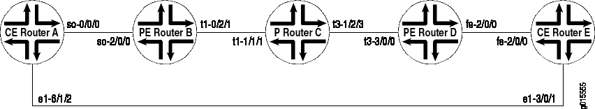
In this topology, CE Router A and CE Router E are in the same AS (AS200). They use EBGP to exchange routes with their respective provider edge (PE) routers, PE Router B and PE Router D. The two CE routers have a back connection.
The following sections describe how to configure the route origin for a group of VPNs:
- Configuring the Site of Origin Community on CE Router A
- Configuring the Community on CE Router A
- Applying the Policy Statement on CE Router A
- Configuring the Policy on PE Router D
- Configuring the Community on PE Router D
- Applying the Policy on PE Router D
Configuring the Site of Origin Community on CE Router A
The following section describes how to configure CE Router A to advertise routes with a site of origin community to PE Router B for this example.
In this example, direct routes are configured to be advertised, but any route can be configured.
Configure a policy to advertise routes with my-soo community on CE Router A as follows:
[edit]
policy-options {
    policy-statement export-to-my-isp {
        term a {
            from {
                protocol direct;
            }
            then {
                community add my-soo;
                accept;
            }
        }
    }
}
Configuring the Community on CE Router A
Configure the my-soo community on CE Router A as
follows:
[edit]
policy-options {
    community my-soo {
        members origin:100:1;
    }
}
Applying the Policy Statement on CE Router A
Apply the export-to-my-isp policy statement as an export policy to the EBGP peering on the CE Router A as follows:
[edit]
protocols {
    bgp {
        group my_isp {
            export export-to-my-isp;
        }
    }
}
When you issue the show route receive-protocol bgp detail command, you should see the following routes originated from PE
Router B with my-soo community:
user@host> show route receive-protocol bgp 10.12.99.2 detail
inet.0: 16 destinations, 16 routes (15 active, 0 holddown, 1 hidden)
inet.3: 2 destinations, 2 routes (2 active, 0 holddown, 0 hidden)
vpn_blue.inet.0: 8 destinations, 10 routes (8 active, 0 holddown, 0 hidden)
* 10.12.33.0/30 (2 entries, 1 announced)
     Nexthop: 10.12.99.2
     AS path: 100 I
     Communities: origin:100:1
  10.12.99.0/30 (2 entries, 1 announced)
     Nexthop: 10.12.99.2
     AS path: 100 I
     Communities: origin:100:1
* 10.255.71.177/32 (1 entry, 1 announced)
     Nexthop: 10.12.99.2
     AS path: 100 I
     Communities: origin:100:1
* 192.168.64.0/21 (1 entry, 1 announced)
     Nexthop: 10.12.99.2
     AS path: 100 I
     Communities: origin:100:1
iso.0: 1 destinations, 1 routes (1 active, 0 holddown, 0 hidden)
mpls.0: 8 destinations, 8 routes (8 active, 0 holddown, 0 hidden)
bgp.l3vpn.0: 4 destinations, 4 routes (4 active, 0 holddown, 0 hidden)
inet6.0: 2 destinations, 2 routes (2 active, 0 holddown, 0 hidden)
__juniper_private1__.inet6.0: 1 destinations, 1 routes (1 active, 0 holddown, 0
hidden)
Configuring the Policy on PE Router D
Configure a policy on PE Router D that prevents routes with my-soo community tagged by CE Router A from being advertised
to CE Router E as follows:
[edit]
policy-options {
    policy-statement soo-ce1-policy {
        term a {
            from {
                community my-soo;
                then {
                    reject;
                }
            }
        }
    }
}
Configuring the Community on PE Router D
Configure the community on PE Router D as follows:
[edit]
policy-options {
    community my-soo {
        members origin:100:1;
    }
}
Applying the Policy on PE Router D
To prevent routes learned from CE Router A from being advertised
to CE Router E (the two routers can communicate these routes directly),
apply the soo-ce1-policy policy statement as an export
policy to the PE Router D and CE Router E EBGP session vpn_blue.
View the EBGP session on PE Router D using the show routing-instances command.
user@host# show routing-instances
vpn_blue {
    instance-type vrf;
    interface fe-2/0/0.0;
    vrf-target target:100:200;
    protocols {
        bgp {
            group ce2 {
                advertise-peer-as;
                peer-as 100;
                neighbor 10.12.99.6;
            }
        }
    }
}
Apply the soo-ce1-policy policy statement as an export
policy to the PE Router D and CE Router E EBGP session vpn_blue as follows:
[edit routing-instances]
vpn_blue {
    protocols {
        bgp {
            group ce2{
                export soo-ce1-policy;
            }
        }
    }
}