Example: Configuring EVPN-MPLS Active-Standby Multihoming
This example shows how to configure Ethernet VPN (EVPN) with MPLS for multihomed customer edge (CE) devices in active-standby redundancy mode. The steps in this example set up:
-
An EVPN routing instance using the
virtual-switchrouting instance type -
Another EVPN routing instance using the
evpnrouting instance type -
A virtual routing and forwarding (VRF) routing instance using the
vrfrouting instance type as part of configuring integrated routing and bridging (IRB) interfaces.
We support active-standby multihoming in EVPN fabrics only with MPLS.
Please refer to EVPN-MPLS: Single-active multihoming support for a complete list of the products that support this feature.
Requirements
This example uses the following hardware and software components:
-
Four MX Series 5G Universal Routing Platforms with MPC interfaces only, where:
-
Two devices are configured as provider edge (PE) routers connected to a common multihomed customer site.
-
One device is configured as a remote PE router connected to a single-homed customer site.
-
-
Eight customer edge (CE) devices, where:
-
Two CE devices are multihomed.
-
Two CE devices are single-homed for each of the PE routers.
-
-
Junos OS Release 14.1 or later running on all the PE routers.
Note:Junos OS Release 14.1 and later releases are based on the EVPN
draft-ietf-l2vpn-evpn-03. Releases prior to 14.1, support the older version of the EVPN draft, causing interoperability issues when Junos OS Release 14.1 and a previous release are running.
Before you begin:
-
Configure the router interfaces.
-
Configure OSPF or any other IGP protocol.
-
Configure BGP.
-
Configure LDP.
-
Configure MPLS.
-
Configure RSVP MPLS LSP or GRE tunnels.
Overview and Topology
This EVPN solution on MX Series routers with MPC interfaces is extended to provide multihoming functionality with active-standby mode of operation. The multihoming functions include autodiscovery of Ethernet segments, Ethernet segment route construction, and Ethernet segment identifier (ESI) label assignment.
In some older Junos releases, the EVPN functionaliy support on MX Series Routers was limited to routers using MPC and MIC interfaces only. See Feature Explorer for platform and release support for any Junos OS feature.
The DPC support for EVPN is provided with the following considerations:
-
DPCs provide support for EVPN in the active-standby mode of operation including support for the following:
-
EVPN instance (EVI)
-
Virtual switch (VS)
-
Integrated routing and bridging (IRB) interfaces
-
-
DPCs intended for providing the EVPN active-standby support should be the CE device-facing line card. The PE device interfaces in the EVPN domain should use only MPC and MIC interfaces.
When configuring active-standby EVPN multihoming, be aware of the following limitations:
-
An interface or ESI can be attached to more than one EVI, with a maximum limit of 200 EVIs per ESI.
-
For an EVPN routing instance, only one logical interface per physical interface or ESI can be attached to an EVI.
-
For a virtual switch routing instance, only one logical interface per physical interface or ESI can be configured under a bridge domain.
-
All the PE routers in the network topology should be running Junos OS Release 14.1 or later, which are based on the EVPN
draft-ietf-l2vpn-evpn-03. Junos OS releases prior to 14.1 support the older version of the EVPN draft, causing interoperability issues when Junos OS Release 14.1 and a previous release are running.
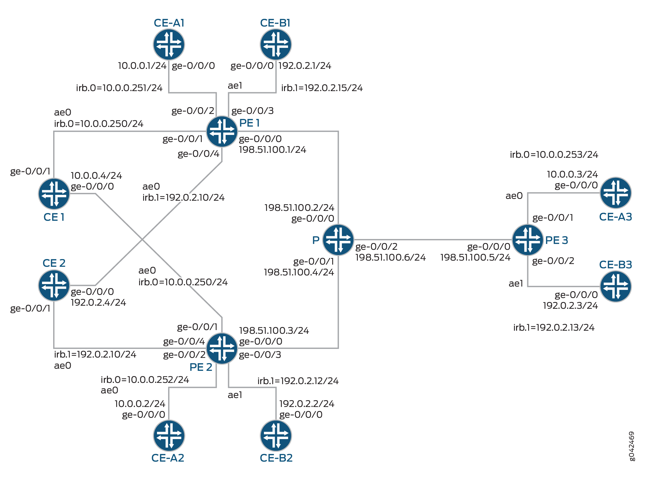
In Figure 1:
-
Routers PE1 and PE2 are provider edge (PE) routers connected to multihomed customer edge (CE) devices “Device CE1” and “Device CE1.”
-
Router PE3 is a remote PE router connected to a single-homed customer site.
-
Router P is the provider router connected to Routers PE1, PE2, and PE3.
-
There are three routing instances running in the topology—ALPHA, BETA, and DELTA—with the virtual switch, EVPN, and VRF type of routing instance, respectively.
-
All the PE routers are connected to one single-homed CE device each for the ALPHA and BETA routing instances.
-
Device CE1 belongs to the ALPHA routing instance, and Device CE2 belongs to the BETA routing instance.
For Router PE1, Device CE-A1 and Device CE-B1 are the single-homed CE devices for the routing instances ALPHA and BETA, respectively. In the same way, Device CE-A2 and Device CE-A3 belong to the ALPHA routing instance, and Device CE-B2 and Device CE-B3 belong to the BETA routing instances connected to Routers PE2 and PE3, respectively.
You can configure active-standby multihoming under any EVPN
routing-instance. We support both evpn and
virtual-switch instance types in active-standby EVPN multihoming. We
include configuration for the tenant VRF routing instance of type vrf to
illustrate the EVPN IRB functionality in addition to multihoming. The DELTA routing
instance configuration is not required for the active-standby EVPN multihoming feature to
work.
For simplicity and consistency of configuration, in this example we configure a route
target extended community for the EVPN instances and VRF instance using the
vrf-target statement at the [edit routing-instances
name] hierarchy level. With this statement, the device
automatically sets import and export routing policies based on the specified community. On
each of the PE devices, we configure corresponding routing instances with route target
values that match, so the PE devices can share routes using those implicit routing
policies. We don't need to explicitly configure import and export policies for route
sharing.
Configuration
CLI Quick Configuration
To quickly configure this example, copy the following commands, paste them into a text file, remove any line breaks, change any details necessary to match your network configuration, and then copy and paste the commands into the CLI at the [edit] hierarchy level.
CE1
>set chassis aggregated-devices ethernet device-count 1
set interfaces ge-0/0/0 gigether-options 802.3ad ae0
set interfaces ge-0/0/1 gigether-options 802.3ad ae0
set interfaces ae0 vlan-tagging
set interfaces ae0 mac 00:00:00:00:00:04
set interfaces ae0 unit 0 vlan-id 100
set interfaces ae0 unit 0 family inet address 10.0.0.4/24
set routing-options static route 0.0.0.0/0 next-hop 10.0.0.250
CE-A1
set chassis aggregated-devices ethernet device-count 1
set interfaces ge-0/0/0 gigether-options 802.3ad ae0
set interfaces ae0 vlan-tagging
set interfaces ae0 mac 00:00:00:00:00:01
set interfaces ae0 unit 0 vlan-id 100
set interfaces ae0 unit 0 family inet address 10.0.0.1/24
set routing-options static route 0.0.0.0/0 next-hop 10.0.0.251
CE-A2
set chassis aggregated-devices ethernet device-count 1
set interfaces ge-0/0/0 gigether-options 802.3ad ae0
set interfaces ae0 vlan-tagging
set interfaces ae0 mac 00:00:00:00:00:02
set interfaces ae0 unit 0 vlan-id 100
set interfaces ae0 unit 0 family inet address 10.0.0.2/24
set routing-options static route 0.0.0.0/0 next-hop 10.0.0.252
CE-A3
set chassis aggregated-devices ethernet device-count 1
set interfaces ge-0/0/0 gigether-options 802.3ad ae0
set interfaces ae0 vlan-tagging
set interfaces ae0 mac 00:00:00:00:00:03
set interfaces ae0 unit 0 vlan-id 100
set interfaces ae0 unit 0 family inet address 10.0.0.3/24
set routing-options static route 0.0.0.0/0 next-hop 10.0.0.253
CE2
set chassis aggregated-devices ethernet device-count 1
set interfaces ge-0/0/0 gigether-options 802.3ad ae0
set interfaces ge-0/0/1 gigether-options 802.3ad ae0
set interfaces ae0 vlan-tagging
set interfaces ae0 mac 00:00:00:00:00:04
set interfaces ae0 unit 0 vlan-id 300
set interfaces ae0 unit 0 family inet address 192.0.2.4/24
set routing-options static route 0.0.0.0/0 next-hop 192.0.2.10
CE-B1
set chassis aggregated-devices ethernet device-count 1
set interfaces ge-0/0/0 gigether-options 802.3ad ae0
set interfaces ae0 vlan-tagging
set interfaces ae0 mac 00:00:00:00:00:01
set interfaces ae0 unit 0 vlan-id 300
set interfaces ae0 unit 0 family inet address 192.0.2.1/24
set routing-options static route 0.0.0.0/0 next-hop 192.0.2.15
CE-B2
set chassis aggregated-devices ethernet device-count 1
set interfaces ge-0/0/0 gigether-options 802.3ad ae0
set interfaces ae0 vlan-tagging
set interfaces ae0 mac 00:00:00:00:00:02
set interfaces ae0 unit 0 vlan-id 300
set interfaces ae0 unit 0 family inet address 192.0.2.4/24
set routing-options static route 0.0.0.0/0 next-hop 192.0.2.12
CE-B3
set chassis aggregated-devices ethernet device-count 1
set interfaces ge-0/0/0 gigether-options 802.3ad ae0
set interfaces ae0 vlan-tagging
set interfaces ae0 mac 00:00:00:00:00:03
set interfaces ae0 unit 0 vlan-id 300
set interfaces ae0 unit 0 family inet address 192.0.2.3/24
set routing-options static route 0.0.0.0/0 next-hop 192.0.2.13
PE1
set interfaces ge-0/0/0 unit 0 family inet address 198.51.100.1/24
set interfaces ge-0/0/0 unit 0 family mpls
set interfaces ge-0/0/1 gigether-options 802.3ad ae0
set interfaces ge-0/0/2 vlan-tagging
set interfaces ge-0/0/2 encapsulation flexible-ethernet-services
set interfaces ge-0/0/2 unit 0 encapsulation vlan-bridge
set interfaces ge-0/0/2 unit 0 vlan-id 100
set interfaces ge-0/0/3 gigether-options 802.3ad ae1
set interfaces ge-0/0/4 vlan-tagging
set interfaces ge-0/0/4 encapsulation flexible-ethernet-services
set interfaces ge-0/0/4 esi 00:22:44:66:88:00:22:44:66:88
set interfaces ge-0/0/4 esi single-active
set interfaces ge-0/0/4 unit 0 encapsulation vlan-bridge
set interfaces ge-0/0/4 unit 0 vlan-id 300
set interfaces ae0 vlan-tagging
set interfaces ae0 encapsulation flexible-ethernet-services
set interfaces ae0 esi 00:11:22:33:44:55:66:77:88:99
set interfaces ae0 esi single-active
set interfaces ae0 unit 0 encapsulation vlan-bridge
set interfaces ae0 unit 0 vlan-id 100
set interfaces ae1 vlan-tagging
set interfaces ae1 encapsulation flexible-ethernet-services
set interfaces ae1 unit 0 encapsulation vlan-bridge
set interfaces ae1 unit 0 vlan-id 300
set interfaces irb unit 0 family inet address 10.0.0.250/24
set interfaces irb unit 0 family inet address 10.0.0.251/24
set interfaces irb unit 0 mac 00:11:22:33:44:55
set interfaces irb unit 1 family inet address 192.0.2.10/24
set interfaces irb unit 1 family inet address 192.0.2.15/24
set interfaces irb unit 1 mac 00:22:44:66:88:00
set interfaces lo0 unit 0 family inet address 10.255.0.1/32 primary
set interfaces lo0 unit 0 family inet address 10.255.0.1/32 preferred
set routing-options router-id 10.255.0.1
set routing-options autonomous-system 100
set routing-options forwarding-table chained-composite-next-hop ingress evpn
set protocols mpls interface lo0.0
set protocols mpls interface ge-0/0/0.0
set protocols bgp group EVPN-PE type internal
set protocols bgp group EVPN-PE local-address 10.255.0.1
set protocols bgp group EVPN-PE family evpn signaling
set protocols bgp group EVPN-PE neighbor 10.255.0.2
set protocols bgp group EVPN-PE neighbor 10.255.0.3
set protocols ospf area 0.0.0.0 interface lo0.0 passive
set protocols ospf area 0.0.0.0 interface ge-0/0/0.0
set protocols ldp interface ge-0/0/0.0
set protocols ldp interface lo0.0
set routing-instances ALPHA instance-type virtual-switch
set routing-instances ALPHA route-distinguisher 10.255.0.1:100
set routing-instances ALPHA vrf-target target:100:100
set routing-instances ALPHA protocols evpn extended-vlan-list 100
set routing-instances ALPHA bridge-domains ONE domain-type bridge
set routing-instances ALPHA bridge-domains ONE vlan-id 100
set routing-instances ALPHA bridge-domains ONE interface ae0.0
set routing-instances ALPHA bridge-domains ONE interface ge-0/0/2.0
set routing-instances ALPHA bridge-domains ONE routing-interface irb.0
set routing-instances BETA instance-type evpn
set routing-instances BETA vlan-id 300
set routing-instances BETA interface ge-0/0/4.0
set routing-instances BETA interface ae1.0
set routing-instances BETA routing-interface irb.1
set routing-instances BETA route-distinguisher 10.255.0.1:300
set routing-instances BETA vrf-target target:300:300
set routing-instances DELTA instance-type vrf
set routing-instances DELTA interface irb.0
set routing-instances DELTA interface irb.1
set routing-instances DELTA route-distinguisher 10.255.0.1:200
set routing-instances DELTA vrf-target target:200:200
set routing-instances DELTA vrf-table-label
PE2
set interfaces ge-0/0/0 unit 0 family inet address 198.51.100.3/24
set interfaces ge-0/0/0 unit 0 family mpls
set interfaces ge-0/0/1 gigether-options 802.3ad ae0
set interfaces ge-0/0/2 vlan-tagging
set interfaces ge-0/0/2 encapsulation flexible-ethernet-services
set interfaces ge-0/0/2 unit 0 encapsulation vlan-bridge
set interfaces ge-0/0/2 unit 0 vlan-id 100
set interfaces ge-0/0/3 gigether-options 802.3ad ae1
set interfaces ge-0/0/4 vlan-tagging
set interfaces ge-0/0/4 encapsulation flexible-ethernet-services
set interfaces ge-0/0/4 esi 00:22:44:66:88:00:22:44:66:88
set interfaces ge-0/0/4 esi single-active
set interfaces ge-0/0/4 unit 0 encapsulation vlan-bridge
set interfaces ge-0/0/4 unit 0 vlan-id 300
set interfaces ae0 vlan-tagging
set interfaces ae0 encapsulation flexible-ethernet-services
set interfaces ae0 esi 00:11:22:33:44:55:66:77:88:99
set interfaces ae0 esi single-active
set interfaces ae0 unit 0 encapsulation vlan-bridge
set interfaces ae0 unit 0 vlan-id 100
set interfaces ae1 vlan-tagging
set interfaces ae1 encapsulation flexible-ethernet-services
set interfaces ae1 unit 0 encapsulation vlan-bridge
set interfaces ae1 unit 0 vlan-id 300
set interfaces irb unit 0 family inet address 10.0.0.250/24
set interfaces irb unit 0 family inet address 10.0.0.252/24
set interfaces irb unit 0 mac 00:11:22:33:44:55
set interfaces irb unit 1 family inet address 192.0.2.10/24
set interfaces irb unit 1 family inet address 192.0.2.12/24
set interfaces irb unit 1 mac 00:22:44:66:88:00
set interfaces lo0 unit 0 family inet address 10.255.0.2/32 primary
set interfaces lo0 unit 0 family inet address 10.255.0.2/32 preferred
set routing-options router-id 10.255.0.2
set routing-options autonomous-system 100
set routing-options forwarding-table chained-composite-next-hop ingress evpn
set protocols mpls interface lo0.0
set protocols mpls interface ge-0/0/0.0
set protocols bgp group EVPN-PE type internal
set protocols bgp group EVPN-PE local-address 10.255.0.2
set protocols bgp group EVPN-PE family evpn signaling
set protocols bgp group EVPN-PE neighbor 10.255.0.1
set protocols bgp group EVPN-PE neighbor 10.255.0.3
set protocols ospf area 0.0.0.0 interface lo0.0 passive
set protocols ospf area 0.0.0.0 interface ge-0/0/0.0
set protocols ldp interface ge-0/0/0.0
set protocols ldp interface lo0.0
set routing-instances ALPHA instance-type virtual-switch
set routing-instances ALPHA route-distinguisher 10.255.0.2:100
set routing-instances ALPHA vrf-target target:100:100
set routing-instances ALPHA protocols evpn extended-vlan-list 100
set routing-instances ALPHA bridge-domains ONE domain-type bridge
set routing-instances ALPHA bridge-domains ONE vlan-id 100
set routing-instances ALPHA bridge-domains ONE interface ae0.0
set routing-instances ALPHA bridge-domains ONE interface ge-0/0/2.0
set routing-instances ALPHA bridge-domains ONE routing-interface irb.0
set routing-instances BETA instance-type evpn
set routing-instances BETA vlan-id 300
set routing-instances BETA interface ge-0/0/4.0
set routing-instances BETA interface ae1.0
set routing-instances BETA routing-interface irb.1
set routing-instances BETA route-distinguisher 10.255.0.2:300
set routing-instances BETA vrf-target target:300:300
set routing-instances DELTA instance-type vrf
set routing-instances DELTA interface irb.0
set routing-instances DELTA interface irb.1
set routing-instances DELTA route-distinguisher 10.255.0.2:200
set routing-instances DELTA vrf-target target:200:200
set routing-instances DELTA vrf-table-label
PE3
set interfaces ge-0/0/0 unit 0 family inet address 198.51.100.5/24
set interfaces ge-0/0/0 unit 0 family mpls
set interfaces ge-0/0/1 gigether-options 802.3ad ae0
set interfaces ge-0/0/2 gigether-options 802.3ad ae1
set interfaces ae0 vlan-tagging
set interfaces ae0 encapsulation flexible-ethernet-services
set interfaces ae0 unit 0 encapsulation vlan-bridge
set interfaces ae0 unit 0 vlan-id 100
set interfaces ae1 vlan-tagging
set interfaces ae1 encapsulation flexible-ethernet-services
set interfaces ae1 unit 0 encapsulation vlan-bridge
set interfaces ae1 unit 0 vlan-id 300
set interfaces irb unit 0 family inet address 10.0.0.253/24
set interfaces irb unit 1 family inet address 192.0.2.13/24
set interfaces lo0 unit 0 family inet address 10.255.0.3/32 primary
set interfaces lo0 unit 0 family inet address 10.255.0.3/32 preferred
set routing-options router-id 10.255.0.3
set routing-options autonomous-system 100
set routing-options forwarding-table chained-composite-next-hop ingress evpn
set protocols mpls interface lo0.0
set protocols mpls interface ge-0/0/0.0
set protocols bgp group EVPN-PE type internal
set protocols bgp group EVPN-PE local-address 10.255.0.3
set protocols bgp group EVPN-PE family evpn signaling
set protocols bgp group EVPN-PE neighbor 10.255.0.1
set protocols bgp group EVPN-PE neighbor 10.255.0.2
set protocols ospf area 0.0.0.0 interface lo0.0 passive
set protocols ospf area 0.0.0.0 interface ge-0/0/0.0
set protocols ldp interface ge-0/0/0.0
set protocols ldp interface lo0.0
set routing-instances ALPHA instance-type virtual-switch
set routing-instances ALPHA route-distinguisher 10.255.0.3:100
set routing-instances ALPHA vrf-target target:100:100
set routing-instances ALPHA protocols evpn extended-vlan-list 100
set routing-instances ALPHA bridge-domains ONE domain-type bridge
set routing-instances ALPHA bridge-domains ONE vlan-id 100
set routing-instances ALPHA bridge-domains ONE interface ae0.0
set routing-instances ALPHA bridge-domains ONE routing-interface irb.0
set routing-instances BETA instance-type evpn
set routing-instances BETA vlan-id 300
set routing-instances BETA interface ae1.0
set routing-instances BETA routing-interface irb.1
set routing-instances BETA route-distinguisher 10.255.0.3:300
set routing-instances BETA vrf-target target:300:300
set routing-instances DELTA instance-type vrf
set routing-instances DELTA interface irb.0
set routing-instances DELTA interface irb.1
set routing-instances DELTA route-distinguisher 10.255.0.3:200
set routing-instances DELTA vrf-target target:200:200
set routing-instances DELTA vrf-table-label
P
set interfaces ge-0/0/0 unit 0 family inet address 198.51.100.2/24
set interfaces ge-0/0/0 unit 0 family mpls
set interfaces ge-0/0/1 unit 0 family inet address 198.51.100.4/24
set interfaces ge-0/0/1 unit 0 family mpls
set interfaces ge-0/0/2 unit 0 family inet address 198.51.100.6/24
set interfaces ge-0/0/2 unit 0 family mpls
set interfaces lo0 unit 0 family inet address 10.255.0.4/32 primary
set interfaces lo0 unit 0 family inet address 10.255.0.4/32 preferred
set routing-options router-id 10.255.0.4
set protocols mpls interface lo0.0
set protocols mpls interface ge-0/0/0.0
set protocols mpls interface ge-0/0/1.0
set protocols mpls interface ge-0/0/2.0
set protocols ospf area 0.0.0.0 interface lo0.0 passive
set protocols ospf area 0.0.0.0 interface ge-0/0/1.0
set protocols ospf area 0.0.0.0 interface ge-0/0/2.0
set protocols ospf area 0.0.0.0 interface ge-0/0/0.0
set protocols ldp interface ge-0/0/0.0
set protocols ldp interface ge-0/0/1.0
set protocols ldp interface ge-0/0/2.0
set protocols ldp interface lo0.0
Procedure
Step-by-Step Procedure
The following example requires you to navigate various levels in the configuration hierarchy. For information about navigating the CLI, see Using the CLI Editor in Configuration Mode.
To configure Router PE1:
Repeat this procedure for Router PE2 after modifying the appropriate interface names, addresses, and other parameters.
-
Configure Router PE1 interfaces.
[edit interfaces]user@PE1# set ge-0/0/0 unit 0 family inet address 198.51.100.1/24 user@PE1# set ge-0/0/0 unit 0 family mpls user@PE1# set ge-0/0/1 gigether-options 802.3ad ae0 user@PE1# set ge-0/0/2 vlan-tagging user@PE1# set ge-0/0/2 encapsulation flexible-ethernet-services user@PE1# set ge-0/0/2 unit 0 encapsulation vlan-bridge user@PE1# set ge-0/0/2 unit 0 vlan-id 100 user@PE1# set ge-0/0/3 gigether-options 802.3ad ae1 user@PE1# set ge-0/0/4 vlan-tagging user@PE1# set ge-0/0/4 encapsulation flexible-ethernet-services user@PE1# set ge-0/0/4 esi 00:22:44:66:88:00:22:44:66:88 user@PE1# set ge-0/0/4 esi single-active user@PE1# set ge-0/0/4 unit 0 encapsulation vlan-bridge user@PE1# set ge-0/0/4 unit 0 vlan-id 300 user@PE1# set ae0 vlan-tagging user@PE1# set ae0 encapsulation flexible-ethernet-services user@PE1# set ae0 esi 00:11:22:33:44:55:66:77:88:99 user@PE1# set ae0 esi single-active user@PE1# set ae0 unit 0 encapsulation vlan-bridge user@PE1# set ae0 unit 0 vlan-id 100 user@PE1# set ae1 vlan-tagging user@PE1# set ae1 encapsulation flexible-ethernet-services user@PE1# set ae1 unit 0 encapsulation vlan-bridge user@PE1# set ae1 unit 0 vlan-id 300 user@PE1# set irb unit 0 family inet address 10.0.0.250/24 user@PE1# set irb unit 0 family inet address 10.0.0.251/24 user@PE1# set irb unit 0 mac 00:11:22:33:44:55 user@PE1# set irb unit 1 family inet address 192.0.2.10/24 user@PE1# set irb unit 1 family inet address 192.0.2.15/24 user@PE1# set irb unit 1 mac 00:22:44:66:88:00 user@PE1# set lo0 unit 0 family inet address 10.255.0.1/32 primary user@PE1# set lo0 unit 0 family inet address 10.255.0.1/32 preferred -
Configure the loopback address of Router PE1 as the router ID.
[edit routing-options]user@PE1# set router-id 10.255.0.1 -
Set the autonomous system number for Router PE1.
[edit routing-options]user@PE1# set autonomous-system 100 -
Enable chained composite next hop for the EVPN.
[edit routing-options]user@PE1# set forwarding-table chained-composite-next-hop ingress evpn -
Enable MPLS on the loopback interface of Router PE1 and the interface connecting PE1 to Router P.
[edit protocols]user@PE1# set mpls interface lo0.0 user@PE1# set mpls interface ge-0/0/0.0 -
Configure the BGP group for Router PE1.
[edit protocols]user@PE1# set bgp group EVPN-PE type internal -
Assign local and neighbor addresses to the EVPN-PE BGP group for Router PE1 to peer with Routers PE2 and PE3.
[edit protocols]user@PE1# set bgp group EVPN-PE local-address 10.255.0.1 user@PE1# set bgp group EVPN-PE neighbor 10.255.0.2 user@PE1# set bgp group EVPN-PE neighbor 10.255.0.3 -
Include the EVPN signaling Network Layer Reachability Information (NLRI) to the EVPN-PE group.
[edit protocols]user@PE1# set bgp group EVPN-PE family evpn signaling -
Configure OSPF on the loopback interface of Router PE1 and the interface connecting PE1 to Router P.
[edit protocols]user@PE1# set ospf area 0.0.0.0 interface lo0.0 passive user@PE1# set ospf area 0.0.0.0 interface ge-0/0/0.0 -
Enable LDP on the loopback interface of Router PE1 and the interface connecting PE1 to Router P.
[edit protocols]user@PE1# set ldp interface lo0.0 user@PE1# set ldp interface ge-0/0/0.0 -
Configure the virtual switch routing instance – ALPHA.
[edit routing-instances]
user@PE1# set ALPHA instance-type virtual-switch
-
Configure the extended VLAN list for the ALPHA routing instance.
[edit routing-instances]
user@PE1# set ALPHA protocols evpn extended-vlan-list 100
-
Set the type for the bridging domain in the ALPHA routing instance.
[edit routing-instances]
user@PE1# set ALPHA bridge-domains ONE domain-type bridge
-
Set the VLAN for the bridging domain in the ALPHA routing instance.
[edit routing-instances]
user@PE1# set ALPHA bridge-domains ONE vlan-id 100
-
Configure the interface names for the ALPHA routing instance.
[edit routing-instances]
user@PE1# set ALPHA bridge-domains ONE interface ae0.0
user@PE1# set ALPHA bridge-domains ONE interface ge-0/0/2.0
user@PE1# set ALPHA bridge-domains ONE routing-interface irb.0
-
Configure the route distinguisher for the ALPHA routing instance.
[edit routing-instances]
user@PE1# set ALPHA route-distinguisher 10.255.0.1:100
-
Configure the VPN routing and forwarding (VRF) target community for the ALPHA routing instance.
[edit routing-instances]
user@PE1# set ALPHA vrf-target target:100:100
-
Configure the EVPN routing instance – BETA.
[edit routing-instances]
user@PE1# set BETA instance-type evpn
-
Set the VLAN identifier for the bridging domain in the BETA routing instance.
[edit routing-instances]
user@PE1# set BETA vlan-id 300
-
Configure the interface names for the BETA routing instance.
[edit routing-instances]
user@PE1# set BETA interface ge-0/0/4.0
user@PE1# set BETA interface ae1.0
user@PE1# set BETA routing-interface irb.1
-
Configure the route distinguisher for the BETA routing instance.
[edit routing-instances]
user@PE1# set BETA route-distinguisher 10.255.0.1:300
-
Configure the VPN routing and forwarding (VRF) target community for the BETA routing instance.
[edit routing-instances]
user@PE1# set BETA vrf-target target:300:300
-
Configure the VRF routing instance – DELTA.
[edit routing-instances]
user@PE1# set DELTA instance-type vrf
-
Configure the interface names for the DELTA routing instance.
[edit routing-instances]
user@PE1# set DELTA interface irb.0
user@PE1# set DELTA interface irb.1
-
Configure the route distinguisher for the DELTA routing instance.
[edit routing-instances]
user@PE1# set DELTA route-distinguisher 10.255.0.1:200
-
Configure the VPN routing and forwarding (VRF) target community for the DELTA routing instance.
[edit routing-instances]
user@PE1# set DELTA vrf-target target:200:200
user@PE1# set DELTA vrf-table-label
Results
From configuration mode, confirm your configuration by entering the show interfaces, show routing-options, show protocols, and show routing-instances commands. If the output does not display the intended configuration, repeat the instructions in this example to correct the configuration.
user@PE1#

                  show interfaces


ge-0/0/0 {
    unit 0 {
        family inet {
            address 198.51.100.1/24;
        }
        family mpls;
    }
}
ge-0/0/1 {
    gigether-options {
        802.3ad ae0;
    }
}
ge-0/0/2 {
    vlan-tagging;
    encapsulation flexible-ethernet-services;
    unit 0 {
        encapsulation vlan-bridge;
        vlan-id 100;
    }
}
ge-0/0/3 {
    gigether-options {
        802.3ad ae1;
    }
}
ge-0/0/4 {
    vlan-tagging;
    encapsulation flexible-ethernet-services;
    esi {
        00:22:44:66:88:00:22:44:66:88;
        single-active;
    }
    unit 0 {
        encapsulation vlan-bridge;
        vlan-id 300;
    }
}
ae0 {
    vlan-tagging;
    encapsulation flexible-ethernet-services;
    esi {
        00:11:22:33:44:55:66:77:88:99;
        single-active;
    }
    unit 0 {
        encapsulation vlan-bridge;
        vlan-id 100;
    }
}
ae1 {
    vlan-tagging;
    encapsulation flexible-ethernet-services;
    unit 0 {
        encapsulation vlan-bridge;
        vlan-id 300;
    }
}
irb {
    unit 0 {
        family inet {
            address 10.0.0.250/24;
            address 10.0.0.251/24;
        }
        mac 00:11:22:33:44:55;
    }
    unit 1 {
        family inet {
            address 192.0.2.10/24;
            address 192.0.2.15/24;
        }
        mac 00:22:44:66:88:00;
    }
}
lo0 {
    unit 0 {
        family inet {
            address 10.255.0.1/32 {
                primary;
                preferred;
            }
        }
    }
}
user@PE1#

                  show routing-options


router-id 10.255.0.1;
autonomous-system 100;
forwarding-table {
    chained-composite-next-hop {
        ingress {
            evpn;
        }
    }
}
user@PE1#

                  show protocols


mpls {
    interface lo0.0;
    interface ge-0/0/0.0;
}
bgp {
    group EVPN-PE {
        type internal;
        local-address 10.255.0.1;
        family evpn {
            signaling;
        }
        neighbor 10.255.0.2;
        neighbor 10.255.0.3;
    }
}
ospf {
    area 0.0.0.0 {
        interface lo0.0 {
            passive;
        }
        interface ge-0/0/0.0;
    }
}
ldp {
    interface ge-0/0/0.0;
    interface lo0.0;
}
user@PE1#

                  show routing-instances


ALPHA {
    instance-type virtual-switch;
    route-distinguisher 10.255.0.1:100;
    vrf-target target:100:100;
    protocols {
        evpn {
            extended-vlan-list 100;
        }
    }
    bridge-domains {
        ONE {
            domain-type bridge;
            vlan-id 100;
            interface ae0.0;
            interface ge-0/0/2.0;
            routing-interface irb.0;
        }
    }
}
BETA {
    instance-type evpn;
    vlan-id 300;
    interface ge-0/0/4.0;
    interface ae1.0;
    routing-interface irb.1;
    route-distinguisher 10.255.0.1:300;
    vrf-target target:300:300;
}
DELTA {
    instance-type vrf;
    interface irb.0;
    interface irb.1;
    route-distinguisher 10.255.0.1:200;
    vrf-target target:200:200;
    vrf-table-label;
}
Verification
Confirm that the configuration is working properly in the following different areas on all the PE routers, where Router PE1 is the designated forwarder (DF), Router PE2 is the non-DF, and Router PE3 is the remote PE:
-
EVPN routing instance configuration
-
EVPN multihoming routes
-
DF election process
-
IRB and virtual switch routing instance configuration
-
Host route entries
- Verifying the EVPN Instance Status
- Verifying the Autodiscovery Routes per Ethernet Segment
- Verifying the Ethernet Segment Route
- Verifying the DF Status
- Verifying the BDF Status
- Verifying Remote IRB MAC
- Verifying Remote IRB and Host IP
- Verifying ARP Table
- Verifying Bridge ARP Table
- Verifying Bridge MAC Table
Verifying the EVPN Instance Status
Purpose
Verify the EVPN routing instances and their status.
Action
Router PE1
From operational mode, run the show evpn instance extensive command.
user@PE1> show evpn instance extensive
Instance: ALPHA
  Route Distinguisher: 10.255.0.1:100
  Per-instance MAC route label: 300144
  Per-instance multicast route label: 300160
  MAC database status                Local  Remote
    Total MAC addresses:                 3       4
    Default gateway MAC addresses:       1       2
  Number of local interfaces: 2 (2 up)
    Interface name  ESI                            Mode             SH label
    ae0.0           00:11:22:33:44:55:66:77:88:99  single-active
    ge-0/0/2.0      00:00:00:00:00:00:00:00:00:00  single-homed
  Number of IRB interfaces: 1 (1 up)
    Interface name  L3 context
    irb.0           DELTA
  Number of neighbors: 2
    10.255.0.2
      Received routes
        MAC address advertisement:              2
        MAC+IP address advertisement:           3
        Inclusive multicast:                    1
        Ethernet auto-discovery:                1
    10.255.0.3
      Received routes
        MAC address advertisement:              2
        MAC+IP address advertisement:           2
        Inclusive multicast:                    1
        Ethernet auto-discovery:                0
  Number of ethernet segments: 1
    ESI: 00:11:22:33:44:55:66:77:88:99
      Designated forwarder: 10.255.0.1
      Backup forwarder: 10.255.0.2

Instance: BETA
  Route Distinguisher: 10.255.0.1:300
  VLAN ID: 300
  Per-instance MAC route label: 300176
  Per-instance multicast route label: 300192
  MAC database status                Local  Remote
    Total MAC addresses:                 3       4
    Default gateway MAC addresses:       1       2
  Number of local interfaces: 2 (2 up)
    Interface name  ESI                            Mode             SH label
    ae1.0           00:00:00:00:00:00:00:00:00:00  single-homed
    ge-0/0/4.0      00:22:44:66:88:00:22:44:66:88  single-active
  Number of IRB interfaces: 1 (1 up)
    Interface name  L3 context
    irb.1           DELTA
  Number of neighbors: 2
    10.255.0.2
      Received routes
        MAC address advertisement:              2
        MAC+IP address advertisement:           3
        Inclusive multicast:                    1
        Ethernet auto-discovery:                1
    10.255.0.3
      Received routes
        MAC address advertisement:              2
        MAC+IP address advertisement:           2
        Inclusive multicast:                    1
        Ethernet auto-discovery:                0
  Number of ethernet segments: 1
    ESI: 00:22:44:66:88:00:22:44:66:88
      Designated forwarder: 10.255.0.1
      Backup forwarder: 10.255.0.2

Instance: __default_evpn__
  Route Distinguisher: 10.255.0.1:0
  VLAN ID: 0
  Per-instance MAC route label: 300208
  Per-instance multicast route label: 300224
  MAC database status                Local  Remote
    Total MAC addresses:                 0       0
    Default gateway MAC addresses:       0       0
  Number of local interfaces: 0 (0 up)
  Number of IRB interfaces: 0 (0 up)
  Number of neighbors: 1
    10.255.0.2
      Received routes
        Ethernet auto-discovery:                0
        Ethernet Segment:                       2
  Number of ethernet segments: 0
Router PE2
From operational mode, run the show evpn instance extensive command.
user@PE2> show evpn instance extensive
Instance: ALPHA
  Route Distinguisher: 10.255.0.2:100
  Per-instance MAC route label: 300208
  Per-instance multicast route label: 300224
  MAC database status                Local  Remote
    Total MAC addresses:                 2       5
    Default gateway MAC addresses:       1       2
  Number of local interfaces: 2 (2 up)
    Interface name  ESI                            Mode             SH label
    ae0.0           00:11:22:33:44:55:66:77:88:99  single-active
    ge-0/0/2.0      00:00:00:00:00:00:00:00:00:00  single-homed
  Number of IRB interfaces: 1 (1 up)
    Interface name  L3 context
    irb.0           DELTA
  Number of neighbors: 2
    10.255.0.1
      Received routes
        MAC address advertisement:              3
        MAC+IP address advertisement:           4
        Inclusive multicast:                    1
        Ethernet auto-discovery:                1
    10.255.0.3
      Received routes
        MAC address advertisement:              2
        MAC+IP address advertisement:           2
        Inclusive multicast:                    1
        Ethernet auto-discovery:                0
  Number of ethernet segments: 1
    ESI: 00:11:22:33:44:55:66:77:88:99
      Designated forwarder: 10.255.0.1
      Backup forwarder: 10.255.0.2

Instance: BETA
  Route Distinguisher: 10.255.0.2:300
  VLAN ID: 300
  Per-instance MAC route label: 300240
  Per-instance multicast route label: 300256
  MAC database status                Local  Remote
    Total MAC addresses:                 2       5
    Default gateway MAC addresses:       1       2
  Number of local interfaces: 2 (2 up)
    Interface name  ESI                            Mode             SH label
    ae1.0           00:00:00:00:00:00:00:00:00:00  single-homed
    ge-0/0/4.0      00:22:44:66:88:00:22:44:66:88  single-active
  Number of IRB interfaces: 1 (1 up)
    Interface name  L3 context
    irb.1           DELTA
  Number of neighbors: 2
    10.255.0.1
      Received routes
        MAC address advertisement:              3
        MAC+IP address advertisement:           4
        Inclusive multicast:                    1
        Ethernet auto-discovery:                1
    10.255.0.3
      Received routes
        MAC address advertisement:              2
        MAC+IP address advertisement:           2
        Inclusive multicast:                    1
        Ethernet auto-discovery:                0
  Number of ethernet segments: 1
    ESI: 00:22:44:66:88:00:22:44:66:88
      Designated forwarder: 10.255.0.1
      Backup forwarder: 10.255.0.2

Instance: __default_evpn__
  Route Distinguisher: 10.255.0.2:0
  VLAN ID: 0
  Per-instance MAC route label: 300272
  Per-instance multicast route label: 300288
  MAC database status                Local  Remote
    Total MAC addresses:                 0       0
    Default gateway MAC addresses:       0       0
  Number of local interfaces: 0 (0 up)
  Number of IRB interfaces: 0 (0 up)
  Number of neighbors: 1
    10.255.0.1
      Received routes
        Ethernet auto-discovery:                0
        Ethernet Segment:                       2
  Number of ethernet segments: 0
Router PE3
From operational mode, run the show evpn instance extensive command.
user@PE3> show evpn instance extensive
Instance: ALPHA
  Route Distinguisher: 10.255.0.3:100
  Per-instance MAC route label: 299776
  Per-instance multicast route label: 299792
  MAC database status                Local  Remote
    Total MAC addresses:                 2       4
    Default gateway MAC addresses:       1       1
  Number of local interfaces: 1 (1 up)
    Interface name  ESI                            Mode             SH label
    ae0.0           00:00:00:00:00:00:00:00:00:00  single-homed
  Number of IRB interfaces: 1 (1 up)
    Interface name  L3 context
    irb.0           DELTA
  Number of neighbors: 2
    10.255.0.1
      Received routes
        MAC address advertisement:              3
        MAC+IP address advertisement:           4
        Inclusive multicast:                    1
        Ethernet auto-discovery:                1
    10.255.0.2
      Received routes
        MAC address advertisement:              2
        MAC+IP address advertisement:           3
        Inclusive multicast:                    1
        Ethernet auto-discovery:                1
  Number of ethernet segments: 0

Instance: BETA
  Route Distinguisher: 10.255.0.3:300
  VLAN ID: 300
  Per-instance MAC route label: 299808
  Per-instance multicast route label: 299824
  MAC database status                Local  Remote
    Total MAC addresses:                 2       4
    Default gateway MAC addresses:       1       1
  Number of local interfaces: 1 (1 up)
    Interface name  ESI                            Mode             SH label
    ae1.0           00:00:00:00:00:00:00:00:00:00  single-homed
  Number of IRB interfaces: 1 (1 up)
    Interface name  L3 context
    irb.1           DELTA
  Number of neighbors: 2
    10.255.0.1
      Received routes
        MAC address advertisement:              3
        MAC+IP address advertisement:           4
        Inclusive multicast:                    1
        Ethernet auto-discovery:                1
    10.255.0.2
      Received routes
        MAC address advertisement:              2
        MAC+IP address advertisement:           3
        Inclusive multicast:                    1
        Ethernet auto-discovery:                1
  Number of ethernet segments: 0

Instance: __default_evpn__
  Route Distinguisher: 10.255.0.3:0
  VLAN ID: 0
  Per-instance MAC route label: 299840
  Per-instance multicast route label: 299856
  MAC database status                Local  Remote
    Total MAC addresses:                 0       0
    Default gateway MAC addresses:       0       0
  Number of local interfaces: 0 (0 up)
  Number of IRB interfaces: 0 (0 up)
  Number of neighbors: 0
  Number of ethernet segments: 0
Meaning
The output provides the following information:
-
List of EVPN and virtual switch routing instances.
-
Mode of operation of each interface
-
Neighbors of each routing instance.
-
Number of different routes received from each neighbor.
-
ESI attached to each routing instance.
-
Number of Ethernet segments on each routing instance.
-
DF election roles for each ESI in an EVI.
-
VLAN ID and MAC labels for each routing instance.
-
IRB interface details
-
Number of default gateway MAC addresses received for the virtual switch routing instance (ALPHA).
Verifying the Autodiscovery Routes per Ethernet Segment
Purpose
Verify that the autodiscovery routes per Ethernet segment are received.
Action
Router PE1
From operational mode, run the show route table ALPHA.evpn.0 command.
user@PE1> show route table ALPHA.evpn.0
ALPHA.evpn.0: 20 destinations, 20 routes (20 active, 0 holddown, 0 hidden)
+ = Active Route, - = Last Active, * = Both

1:10.255.0.2:0::112233445566778899::0/304
                   *[BGP/170] 2d 23:51:27, localpref 100, from 10.255.0.2
                      AS path: I, validation-state: unverified
                    > to 198.51.100.2 via ge-0/0/0.0, Push 299808
2:10.255.0.1:100::100::00:00:00:00:00:01/304
                   *[EVPN/170] 2d 23:52:22
                      Indirect
2:10.255.0.1:100::100::00:00:00:00:00:04/304
                   *[EVPN/170] 2d 23:52:24
                      Indirect
2:10.255.0.1:100::100::00:11:22:33:44:55/304
                   *[EVPN/170] 2d 23:53:32
                      Indirect
2:10.255.0.2:100::100::00:00:00:00:00:02/304
                   *[BGP/170] 2d 23:51:27, localpref 100, from 10.255.0.2
                      AS path: I, validation-state: unverified
                    > to 198.51.100.2 via ge-0/0/0.0, Push 299808
2:10.255.0.2:100::100::00:11:22:33:44:55/304
                   *[BGP/170] 2d 23:51:27, localpref 100, from 10.255.0.2
                      AS path: I, validation-state: unverified
                    > to 198.51.100.2 via ge-0/0/0.0, Push 299808
2:10.255.0.3:100::100::00:00:00:00:00:03/304
                   *[BGP/170] 2d 23:39:04, localpref 100, from 10.255.0.3
                      AS path: I, validation-state: unverified
                    > to 198.51.100.2 via ge-0/0/0.0, Push 299824
2:10.255.0.3:100::100::00:05:86:71:b3:f0/304
                   *[BGP/170] 2d 23:39:24, localpref 100, from 10.255.0.3
                      AS path: I, validation-state: unverified
                    > to 198.51.100.2 via ge-0/0/0.0, Push 299824
2:10.255.0.1:100::100::00:00:00:00:00:01::10.0.0.1/304
                   *[EVPN/170] 2d 23:52:22
                      Indirect
2:10.255.0.1:100::100::00:00:00:00:00:04::10.0.0.4/304
                   *[EVPN/170] 2d 23:52:24
                      Indirect
2:10.255.0.1:100::100::00:11:22:33:44:55::10.0.0.250/304
                   *[EVPN/170] 2d 23:53:32
                      Indirect
2:10.255.0.1:100::100::00:11:22:33:44:55::10.0.0.251/304
                   *[EVPN/170] 2d 23:53:32
                      Indirect
2:10.255.0.2:100::100::00:00:00:00:00:02::10.0.0.2/304
                   *[BGP/170] 2d 23:51:27, localpref 100, from 10.255.0.2
                      AS path: I, validation-state: unverified
                    > to 198.51.100.2 via ge-0/0/0.0, Push 299808
2:10.255.0.2:100::100::00:11:22:33:44:55::10.0.0.250/304
                   *[BGP/170] 2d 23:51:27, localpref 100, from 10.255.0.2
                      AS path: I, validation-state: unverified
                    > to 198.51.100.2 via ge-0/0/0.0, Push 299808
2:10.255.0.2:100::100::00:11:22:33:44:55::10.0.0.252/304
                   *[BGP/170] 2d 23:51:27, localpref 100, from 10.255.0.2
                      AS path: I, validation-state: unverified
                    > to 198.51.100.2 via ge-0/0/0.0, Push 299808
2:10.255.0.3:100::100::00:00:00:00:00:03::10.0.0.3/304
                   *[BGP/170] 2d 23:39:04, localpref 100, from 10.255.0.3
                      AS path: I, validation-state: unverified
                    > to 198.51.100.2 via ge-0/0/0.0, Push 299824
2:10.255.0.3:100::100::00:05:86:71:b3:f0::10.0.0.253/304
                   *[BGP/170] 2d 23:39:24, localpref 100, from 10.255.0.3
                      AS path: I, validation-state: unverified
                    > to 198.51.100.2 via ge-0/0/0.0, Push 299824
3:10.255.0.1:100::100::10.255.0.1/304
                   *[EVPN/170] 2d 23:52:33
                      Indirect
3:10.255.0.2:100::100::10.255.0.2/304
                   *[BGP/170] 2d 23:51:27, localpref 100, from 10.255.0.2
                      AS path: I, validation-state: unverified
                    > to 198.51.100.2 via ge-0/0/0.0, Push 299808
3:10.255.0.3:100::100::10.255.0.3/304
                   *[BGP/170] 2d 23:39:24, localpref 100, from 10.255.0.3
                      AS path: I, validation-state: unverified
                    > to 198.51.100.2 via ge-0/0/0.0, Push 299824
Router PE2
From operational mode, run the show route table ALPHA.evpn.0 command.
user@PE2> show show route table ALPHA.evpn.0
ALPHA.evpn.0: 20 destinations, 20 routes (20 active, 0 holddown, 0 hidden)
+ = Active Route, - = Last Active, * = Both

1:10.255.0.1:0::112233445566778899::0/304
                   *[BGP/170] 10:46:04, localpref 100, from 10.255.0.1
                      AS path: I, validation-state: unverified
                    > to 198.51.100.4 via ge-0/0/0.0, Push 299776
2:10.255.0.1:100::100::00:00:00:00:00:01/304
                   *[BGP/170] 10:43:51, localpref 100, from 10.255.0.1
                      AS path: I, validation-state: unverified
                    > to 198.51.100.4 via ge-0/0/0.0, Push 299776
2:10.255.0.1:100::100::00:00:00:00:00:04/304
                   *[BGP/170] 10:45:06, localpref 100, from 10.255.0.1
                      AS path: I, validation-state: unverified
                    > to 198.51.100.4 via ge-0/0/0.0, Push 299776
2:10.255.0.1:100::100::00:11:22:33:44:55/304
                   *[BGP/170] 10:46:04, localpref 100, from 10.255.0.1
                      AS path: I, validation-state: unverified
                    > to 198.51.100.4 via ge-0/0/0.0, Push 299776
2:10.255.0.2:100::100::00:00:00:00:00:02/304
                   *[EVPN/170] 10:43:48
                      Indirect
2:10.255.0.2:100::100::00:11:22:33:44:55/304
                   *[EVPN/170] 10:46:04
                      Indirect
2:10.255.0.3:100::100::00:00:00:00:00:03/304
                   *[BGP/170] 10:46:04, localpref 100, from 10.255.0.3
                      AS path: I, validation-state: unverified
                    > to 198.51.100.4 via ge-0/0/0.0, Push 299792
2:10.255.0.3:100::100::00:05:86:71:79:f0/304
                   *[BGP/170] 10:46:04, localpref 100, from 10.255.0.3
                      AS path: I, validation-state: unverified
                    > to 198.51.100.4 via ge-0/0/0.0, Push 299792
2:10.255.0.1:100::100::00:00:00:00:00:01::10.0.0.1/304
                   *[BGP/170] 10:41:52, localpref 100, from 10.255.0.1
                      AS path: I, validation-state: unverified
                    > to 198.51.100.4 via ge-0/0/0.0, Push 299776
2:10.255.0.1:100::100::00:00:00:00:00:04::10.0.0.4/304
                   *[BGP/170] 10:45:06, localpref 100, from 10.255.0.1
                      AS path: I, validation-state: unverified
                    > to 198.51.100.4 via ge-0/0/0.0, Push 299776
2:10.255.0.1:100::100::00:11:22:33:44:55::10.0.0.250/304
                   *[BGP/170] 10:46:04, localpref 100, from 10.255.0.1
                      AS path: I, validation-state: unverified
                    > to 198.51.100.4 via ge-0/0/0.0, Push 299776
2:10.255.0.1:100::100::00:11:22:33:44:55::10.0.0.251/304
                   *[BGP/170] 10:46:04, localpref 100, from 10.255.0.1
                      AS path: I, validation-state: unverified
                    > to 198.51.100.4 via ge-0/0/0.0, Push 299776
2:10.255.0.2:100::100::00:00:00:00:00:02::10.0.0.2/304
                   *[EVPN/170] 10:40:25
                      Indirect
2:10.255.0.2:100::100::00:11:22:33:44:55::10.0.0.250/304
                   *[EVPN/170] 10:46:04
                      Indirect
2:10.255.0.2:100::100::00:11:22:33:44:55::10.0.0.252/304
                   *[EVPN/170] 10:46:04
                      Indirect
2:10.255.0.3:100::100::00:00:00:00:00:03::10.0.0.3/304
                   *[BGP/170] 10:46:04, localpref 100, from 10.255.0.3
                      AS path: I, validation-state: unverified
                    > to 198.51.100.4 via ge-0/0/0.0, Push 299792
2:10.255.0.3:100::100::00:05:86:71:79:f0::10.0.0.253/304
                   *[BGP/170] 10:46:04, localpref 100, from 10.255.0.3
                      AS path: I, validation-state: unverified
                    > to 198.51.100.4 via ge-0/0/0.0, Push 299792
3:10.255.0.1:100::100::10.255.0.1/304
                   *[BGP/170] 10:46:04, localpref 100, from 10.255.0.1
                      AS path: I, validation-state: unverified
                    > to 198.51.100.4 via ge-0/0/0.0, Push 299776
3:10.255.0.2:100::100::10.255.0.2/304
                   *[EVPN/170] 10:46:04
                      Indirect
3:10.255.0.3:100::100::10.255.0.3/304
                   *[BGP/170] 10:46:04, localpref 100, from 10.255.0.3
                      AS path: I, validation-state: unverified
                    > to 198.51.100.4 via ge-0/0/0.0, Push 299792
Router PE3
From operational mode, run the show route table ALPHA.evpn.0 command.
user@PE3> show route table ALPHA.evpn.0
ALPHA.evpn.0: 21 destinations, 21 routes (21 active, 0 holddown, 0 hidden)
+ = Active Route, - = Last Active, * = Both

1:10.255.0.1:0::112233445566778899::0/304
                   *[BGP/170] 10:47:43, localpref 100, from 10.255.0.1
                      AS path: I, validation-state: unverified
                    > to 198.51.100.6 via ge-0/0/0.0, Push 299776
1:10.255.0.2:0::112233445566778899::0/304
                   *[BGP/170] 10:47:34, localpref 100, from 10.255.0.2
                      AS path: I, validation-state: unverified
                    > to 198.51.100.6 via ge-0/0/0.0, Push 299808
2:10.255.0.1:100::100::00:00:00:00:00:01/304
                   *[BGP/170] 10:45:21, localpref 100, from 10.255.0.1
                      AS path: I, validation-state: unverified
                    > to 198.51.100.6 via ge-0/0/0.0, Push 299776
2:10.255.0.1:100::100::00:00:00:00:00:04/304
                   *[BGP/170] 10:46:36, localpref 100, from 10.255.0.1
                      AS path: I, validation-state: unverified
                    > to 198.51.100.6 via ge-0/0/0.0, Push 299776
2:10.255.0.1:100::100::00:11:22:33:44:55/304
                   *[BGP/170] 10:47:43, localpref 100, from 10.255.0.1
                      AS path: I, validation-state: unverified
                    > to 198.51.100.6 via ge-0/0/0.0, Push 299776
2:10.255.0.2:100::100::00:00:00:00:00:02/304
                   *[BGP/170] 10:45:18, localpref 100, from 10.255.0.2
                      AS path: I, validation-state: unverified
                    > to 198.51.100.6 via ge-0/0/0.0, Push 299808
2:10.255.0.2:100::100::00:11:22:33:44:55/304
                   *[BGP/170] 10:47:34, localpref 100, from 10.255.0.2
                      AS path: I, validation-state: unverified
                    > to 198.51.100.6 via ge-0/0/0.0, Push 299808
2:10.255.0.3:100::100::00:00:00:00:00:03/304
                   *[EVPN/170] 10:59:05
                      Indirect
2:10.255.0.3:100::100::00:05:86:71:79:f0/304
                   *[EVPN/170] 11:00:23
                      Indirect
2:10.255.0.1:100::100::00:00:00:00:00:01::10.0.0.1/304
                   *[BGP/170] 10:43:22, localpref 100, from 10.255.0.1
                      AS path: I, validation-state: unverified
                    > to 198.51.100.6 via ge-0/0/0.0, Push 299776
2:10.255.0.1:100::100::00:00:00:00:00:04::10.0.0.4/304
                   *[BGP/170] 10:46:36, localpref 100, from 10.255.0.1
                      AS path: I, validation-state: unverified
                    > to 198.51.100.6 via ge-0/0/0.0, Push 299776
2:10.255.0.1:100::100::00:11:22:33:44:55::10.0.0.250/304
                   *[BGP/170] 10:47:43, localpref 100, from 10.255.0.1
                      AS path: I, validation-state: unverified
                    > to 198.51.100.6 via ge-0/0/0.0, Push 299776
2:10.255.0.1:100::100::00:11:22:33:44:55::10.0.0.251/304
                   *[BGP/170] 10:47:43, localpref 100, from 10.255.0.1
                      AS path: I, validation-state: unverified
                    > to 198.51.100.6 via ge-0/0/0.0, Push 299776
2:10.255.0.2:100::100::00:00:00:00:00:02::10.0.0.2/304
                   *[BGP/170] 10:41:55, localpref 100, from 10.255.0.2
                      AS path: I, validation-state: unverified
                    > to 198.51.100.6 via ge-0/0/0.0, Push 299808
2:10.255.0.2:100::100::00:11:22:33:44:55::10.0.0.250/304
                   *[BGP/170] 10:47:34, localpref 100, from 10.255.0.2
                      AS path: I, validation-state: unverified
                    > to 198.51.100.6 via ge-0/0/0.0, Push 299808
2:10.255.0.2:100::100::00:11:22:33:44:55::10.0.0.252/304
                   *[BGP/170] 10:47:34, localpref 100, from 10.255.0.2
                      AS path: I, validation-state: unverified
                    > to 198.51.100.6 via ge-0/0/0.0, Push 299808
2:10.255.0.3:100::100::00:00:00:00:00:03::10.0.0.3/304
                   *[EVPN/170] 10:59:05
                      Indirect
2:10.255.0.3:100::100::00:05:86:71:79:f0::10.0.0.253/304
                   *[EVPN/170] 11:00:23
                      Indirect
3:10.255.0.1:100::100::10.255.0.1/304
                   *[BGP/170] 10:47:43, localpref 100, from 10.255.0.1
                      AS path: I, validation-state: unverified
                    > to 198.51.100.6 via ge-0/0/0.0, Push 299776
3:10.255.0.2:100::100::10.255.0.2/304
                   *[BGP/170] 10:47:34, localpref 100, from 10.255.0.2
                      AS path: I, validation-state: unverified
                    > to 198.51.100.6 via ge-0/0/0.0, Push 299808
3:10.255.0.3:100::100::10.255.0.3/304
                   *[EVPN/170] 10:59:40
                      Indirect
Meaning
The remote type 1 autodiscovery route is received for the ESI attached to Router PE2, which is the other PE router connected to the multihomed CE device.
Verifying the Ethernet Segment Route
Purpose
Verify that the local and advertised autodiscovery routes per Ethernet segment and the Ethernet segment routes are received.
Action
Router PE1
From operational mode, run the show route table __default_evpn__.evpn.0 command.
user@PE1> show route table __default_evpn__.evpn.0
__default_evpn__.evpn.0: 6 destinations, 6 routes (6 active, 0 holddown, 0 hidden)
+ = Active Route, - = Last Active, * = Both

1:10.255.0.1:0::112233445566778899::0/304
                   *[EVPN/170] 3d 00:00:31
                      Indirect
1:10.255.0.1:0::224466880022446688::0/304
                   *[EVPN/170] 3d 00:00:31
                      Indirect
4:10.255.0.1:0::112233445566778899:10.255.0.1/304
                   *[EVPN/170] 3d 00:00:31
                      Indirect
4:10.255.0.1:0::224466880022446688:10.255.0.1/304
                   *[EVPN/170] 3d 00:00:31
                      Indirect
4:10.255.0.2:0::112233445566778899:10.255.0.2/304
                   *[BGP/170] 3d 00:00:20, localpref 100, from 10.255.0.2
                      AS path: I, validation-state: unverified
                    > to 198.51.100.2 via ge-0/0/0.0, Push 299808
4:10.255.0.2:0::224466880022446688:10.255.0.2/304
                   *[BGP/170] 3d 00:00:20, localpref 100, from 10.255.0.2
                      AS path: I, validation-state: unverified
                    > to 198.51.100.2 via ge-0/0/0.0, Push 299808
Router PE2
From operational mode, run the show route table __default_evpn__.evpn.0 command.
user@PE2> show route table __default_evpn__.evpn.0
__default_evpn__.evpn.0: 6 destinations, 6 routes (6 active, 0 holddown, 0 hidden)
+ = Active Route, - = Last Active, * = Both

1:10.255.0.2:0::112233445566778899::0/304
                   *[EVPN/170] 10:49:26
                      Indirect
1:10.255.0.2:0::224466880022446688::0/304
                   *[EVPN/170] 10:49:26
                      Indirect
4:10.255.0.1:0::112233445566778899:10.255.0.1/304
                   *[BGP/170] 10:49:26, localpref 100, from 10.255.0.1
                      AS path: I, validation-state: unverified
                    > to 198.51.100.4 via ge-0/0/0.0, Push 299776
4:10.255.0.1:0::224466880022446688:10.255.0.1/304
                   *[BGP/170] 10:49:26, localpref 100, from 10.255.0.1
                      AS path: I, validation-state: unverified
                    > to 198.51.100.4 via ge-0/0/0.0, Push 299776
4:10.255.0.2:0::112233445566778899:10.255.0.2/304
                   *[EVPN/170] 10:49:26
                      Indirect
4:10.255.0.2:0::224466880022446688:10.255.0.2/304
                   *[EVPN/170] 10:49:26
                      Indirect
Meaning
The output displays the local and remote type 1 (autodiscovery) and type 4 (Ethernet segment) routes:
-
1:10.255.0.1:0::112233445566778899::0/304—Autodiscovery route per Ethernet segment for each local ESI attached to Router PE1 and Router PE2. -
4:10.255.0.1:0::112233445566778899:10.255.0.1/304—Ethernet segment route for each local ESI attached to Router PE1 and Router PE2. -
4:10.255.0.2:0::112233445566778899:10.255.0.2/304—Remote Ethernet segment route from Router PE2.
Verifying the DF Status
Purpose
Confirm which PE router is the designated forwarder (DF).
Action
From operational mode, run the show evpn instance ALPHA esi esi designated-forwarder command.
user@PE1> show evpn instance ALPHA esi 00:11:22:33:44:55:66:77:88:99
designated-forwarder
Instance: ALPHA
  Number of ethernet segments: 1
    ESI: 00:11:22:33:44:55:66:77:88:99
      Designated forwarder: 10.255.0.1
Meaning
Router PE1 is the DF for the ALPHA routing instance.
Verifying the BDF Status
Purpose
Confirm which PE router is the backup designated forwarder (BDF).
Action
From operational mode, run the show evpn instance ALPHA esi esi backup-forwarder command.
user@PE1> show evpn instance ALPHA esi 00:11:22:33:44:55:66:77:88:99
backup-forwarder
Instance: ALPHA
  Number of ethernet segments: 1
    ESI: 00:11:22:33:44:55:66:77:88:99
      Backup forwarder: 10.255.0.2
Meaning
Router PE2 is the BDF for the ALPHA routing instance.
Verifying Remote IRB MAC
Purpose
Verify that the remote gateway MAC addresses are synchronized among all the PE routers.
Action
Router PE1
From operational mode, run the show bridge evpn peer-gateway-mac command.
user@PE1> show bridge evpn peer-gateway-mac
Routing instance : ALPHA
 Bridging domain : ONE, VLAN : 100
  Installed GW MAC addresses:
  00:05:86:71:79:f0
Router PE2
From operational mode, run the show bridge evpn peer-gateway-mac command.
user@PE2> show bridge evpn peer-gateway-mac
Routing instance : ALPHA
 Bridging domain : ONE, VLAN : 100
  Installed GW MAC addresses:
  00:05:86:71:79:f0
Router PE3
From operational mode, run the show bridge evpn peer-gateway-mac command.
user@PE2> show bridge evpn peer-gateway-mac
Routing instance : ALPHA
 Bridging domain : ONE, VLAN : 100
  Installed GW MAC addresses:
  00:11:22:33:44:55
Meaning
The remote gateway MAC addresses are synchronized:
-
Router PE3 gateway MAC is installed in Routers PE1 and PE2 peer-gateway-mac table.
-
Routers PE1 and PE2 gateway MAC addresses are installed in Router PE3 peer-gateway-mac table.
Verifying Remote IRB and Host IP
Purpose
Verify that the remote IRB IP and the host IP are received.
Action
Router PE1
From operational mode, run the show route table DELTA command.
user@PE1> show route table DELTA
DELTA.inet.0: 16 destinations, 18 routes (16 active, 0 holddown, 0 hidden)
+ = Active Route, - = Last Active, * = Both

10.0.0.0/24        *[Direct/0] 11:25:54
                    > via irb.0
                    [Direct/0] 11:25:54
                    > via irb.0
10.0.0.1/32        *[EVPN/7] 11:21:33
                    > via irb.0
10.0.0.2/32        *[EVPN/7] 11:20:06, metric2 1
                    > to 198.51.100.2 via ge-0/0/0.0, Push 300208, Push 299808(top)
10.0.0.3/32        *[EVPN/7] 11:25:54, metric2 1
                    > to 198.51.100.2 via ge-0/0/0.0, Push 299776, Push 299792(top)
10.0.0.4/32        *[EVPN/7] 11:24:47
                    > via irb.0
10.0.0.250/32      *[Local/0] 11:38:29
                      Local via irb.0
10.0.0.251/32      *[Local/0] 11:38:29
                      Local via irb.0
10.0.0.253/32      *[EVPN/7] 11:25:54, metric2 1
                    > to 198.51.100.2 via ge-0/0/0.0, Push 299776, Push 299792(top)
192.0.2.0/24        *[Direct/0] 11:25:55
                    > via irb.1
                    [Direct/0] 11:25:55
                    > via irb.1
192.0.2.1/24        *[EVPN/7] 11:21:20
                    > via irb.1
192.0.2.2/24        *[EVPN/7] 11:19:54, metric2 1
                    > to 198.51.100.2 via ge-0/0/0.0, Push 300240, Push 299808(top)
192.0.2.3/24       *[EVPN/7] 11:25:54, metric2 1
                    > to 198.51.100.2 via ge-0/0/0.0, Push 299808, Push 299792(top)
192.0.2.4/24        *[EVPN/7] 11:24:40
                    > via irb.1
192.0.2.10/24      *[Local/0] 11:38:29
                      Local via irb.1
192.0.2.15/24      *[Local/0] 11:38:29
                      Local via irb.1
192.0.2.13/24      *[EVPN/7] 11:25:54, metric2 1
                    > to 198.51.100.2 via ge-0/0/0.0, Push 299808, Push 299792(top)
Router PE2
From operational mode, run the show route table DELTA command.
user@PE2> show route table DELTA
DELTA.inet.0: 16 destinations, 18 routes (16 active, 0 holddown, 0 hidden)
+ = Active Route, - = Last Active, * = Both

10.0.0.0/24        *[Direct/0] 11:30:02
                    > via irb.0
                    [Direct/0] 11:30:02
                    > via irb.0
10.0.0.1/32        *[EVPN/7] 11:25:50, metric2 1
                    > to 198.51.100.4 via ge-0/0/0.0, Push 300144, Push 299776(top)
10.0.0.2/32        *[EVPN/7] 11:24:23
                    > via irb.0
10.0.0.3/32        *[EVPN/7] 11:30:02, metric2 1
                    > to 198.51.100.4 via ge-0/0/0.0, Push 299776, Push 299792(top)
10.0.0.4/32        *[EVPN/7] 11:29:04, metric2 1
                    > to 198.51.100.4 via ge-0/0/0.0, Push 300144, Push 299776(top)
10.0.0.250/32      *[Local/0] 11:42:33
                      Local via irb.0
10.0.0.252/32      *[Local/0] 11:42:33
                      Local via irb.0
10.0.0.253/32      *[EVPN/7] 11:30:02, metric2 1
                    > to 198.51.100.4 via ge-0/0/0.0, Push 299776, Push 299792(top)
192.0.2.0/24        *[Direct/0] 11:30:02
                    > via irb.1
                    [Direct/0] 11:30:02
                    > via irb.1
192.0.2.1/24        *[EVPN/7] 11:25:37, metric2 1
                    > to 198.51.100.4 via ge-0/0/0.0, Push 300176, Push 299776(top)
192.0.2.2/24        *[EVPN/7] 11:24:11
                    > via irb.1
192.0.2.3/24       *[EVPN/7] 11:30:02, metric2 1
                    > to 198.51.100.4 via ge-0/0/0.0, Push 299808, Push 299792(top)
192.0.2.4/24        *[EVPN/7] 11:28:57, metric2 1
                    > to 198.51.100.4 via ge-0/0/0.0, Push 300176, Push 299776(top)
192.0.2.10/24      *[Local/0] 11:42:33
                      Local via irb.1
192.0.2.12/24      *[Local/0] 11:42:33
                      Local via irb.1
192.0.2.13/24      *[EVPN/7] 11:30:02, metric2 1
                    > to 198.51.100.4 via ge-0/0/0.0, Push 299808, Push 299792(top)
Router PE3
From operational mode, run the show route table DELTA command.
user@PE3> show route table DELTA
DELTA.inet.0: 16 destinations, 16 routes (16 active, 0 holddown, 0 hidden)
+ = Active Route, - = Last Active, * = Both

10.0.0.0/24        *[Direct/0] 11:42:15
                    > via irb.0
10.0.0.1/32        *[EVPN/7] 11:25:56, metric2 1
                    > to 198.51.100.6 via ge-0/0/0.0, Push 300144, Push 299776(top)
10.0.0.2/32        *[EVPN/7] 11:24:29, metric2 1
                    > to 198.51.100.6 via ge-0/0/0.0, Push 300208, Push 299808(top)
10.0.0.3/32        *[EVPN/7] 11:41:39
                    > via irb.0
10.0.0.4/32        *[EVPN/7] 11:29:10, metric2 1
                    > to 198.51.100.6 via ge-0/0/0.0, Push 300144, Push 299776(top)
10.0.0.250/32      *[EVPN/7] 11:30:08, metric2 1
                    > to 198.51.100.6 via ge-0/0/0.0, Push 300208, Push 299808(top)
10.0.0.252/32      *[EVPN/7] 11:30:08, metric2 1
                    > to 198.51.100.6 via ge-0/0/0.0, Push 300208, Push 299808(top)
10.0.0.253/32      *[Local/0] 11:42:57
                      Local via irb.0
192.0.2.0/24        *[Direct/0] 11:42:15
                    > via irb.1
192.0.2.1/24        *[EVPN/7] 11:25:43, metric2 1
                    > to 198.51.100.6 via ge-0/0/0.0, Push 300176, Push 299776(top)
192.0.2.2/24        *[EVPN/7] 11:24:17, metric2 1
                    > to 198.51.100.6 via ge-0/0/0.0, Push 300240, Push 299808(top)
192.0.2.3/24       *[EVPN/7] 11:42:04
                    > via irb.1
192.0.2.4/24        *[EVPN/7] 11:29:03, metric2 1
                    > to 198.51.100.6 via ge-0/0/0.0, Push 300176, Push 299776(top)
192.0.2.10/24      *[EVPN/7] 11:30:08, metric2 1
                    > to 198.51.100.6 via ge-0/0/0.0, Push 300240, Push 299808(top)
192.0.2.12/24      *[EVPN/7] 11:30:08, metric2 1
                    > to 198.51.100.6 via ge-0/0/0.0, Push 300240, Push 299808(top)
192.0.2.13/24      *[Local/0] 11:42:57
                      Local via irb.1
Meaning
The output displays the local and remote IRB interfaces. It also displays the local and remote hosts that are installed in the VRF table:
On Router PE1:
-
10.0.0.1/32—Local host in the virtual switch routing instance. -
10.0.0.2/32and10.0.0.3/32—Remote host in the virtual switch routing instance. -
10.0.0.250/32—Local IRB in the virtual switch routing instance. -
10.0.0.253/32—Remote IRB in the virtual switch routing instance.
Verifying ARP Table
Purpose
Verify the ARP table entries.
Action
Router PE1
From operational mode, run the show evpn arp-table command.
user@PE1> show evpn arp-table
INET                MAC                Logical       Routing      Bridging
address             address            interface     instance     domain
192.0.2.1            00:00:00:00:00:01  irb.1         BETA         __BETA__
192.0.2.4            00:00:00:00:00:04  irb.1         BETA         __BETA__
Router PE2
From operational mode, run the show evpn arp-table command.
user@PE2> show evpn arp-table
INET                MAC                Logical       Routing      Bridging
address             address            interface     instance     domain
192.0.2.2            00:00:00:00:00:02  irb.1         BETA         __BETA__
Router PE3
From operational mode, run the show evpn arp-table command.
user@PE3> show evpn arp-table
INET                MAC                Logical       Routing      Bridging
address             address            interface     instance     domain
192.0.2.3            00:00:00:00:00:03  irb.1         BETA         __BETA__
Meaning
The EVPN instance and ARP are synchronized with the host MAC and IP address for local hosts.
Verifying Bridge ARP Table
Purpose
Verify the bridge ARP table entries.
Action
Router PE1
From operational mode, run the show bridge evpn arp-table command.
user@PE3> show bridge evpn arp-table
INET                MAC                Logical       Routing      Bridging
address             address            interface     instance     domain
10.0.0.1            00:00:00:00:00:01  irb.0         ALPHA        ONE
10.0.0.4            00:00:00:00:00:04  irb.0         ALPHA        ONE
Router PE2
From operational mode, run the show bridge evpn arp-table command.
user@PE3> show bridge evpn arp-table
INET                MAC                Logical       Routing      Bridging
address             address            interface     instance     domain
10.0.0.2            00:00:00:00:00:02  irb.0         ALPHA        ONE
Router PE3
From operational mode, run the show bridge evpn arp-table command.
user@PE3> show bridge evpn arp-table
INET                MAC                Logical       Routing      Bridging
address             address            interface     instance     domain
10.0.0.3            00:00:00:00:00:03  irb.0         ALPHA        ONE
Meaning
The virtual switch instance and ARP are synchronized with the local host MAC and IP address.
Verifying Bridge MAC Table
Purpose
Verify the bridge MAC table entries.
Action
Router PE1
From operational mode, run the show bridge mac-table command.
user@PE1> show bridge mac-table
MAC flags (S -static MAC, D -dynamic MAC, L -locally learned, C -Control MAC
           SE -Statistics enabled, NM -Non configured MAC, R -Remote PE MAC)

Routing instance : ALPHA
 Bridging domain : ONE, VLAN : 100
   MAC                 MAC      Logical          NH     RTR
   address             flags    interface        Index  ID
   00:00:00:00:00:01   D        ge-0/0/2.0
   00:00:00:00:00:02   DC                        1048583 1048583
   00:00:00:00:00:03   DC                        1048574 1048574
   00:00:00:00:00:04   D        ae0.0
Router PE2
From operational mode, run the show bridge mac-table command.
user@PE2> show bridge mac-table
MAC flags (S -static MAC, D -dynamic MAC, L -locally learned, C -Control MAC
           SE -Statistics enabled, NM -Non configured MAC, R -Remote PE MAC)

Routing instance : ALPHA
 Bridging domain : ONE, VLAN : 100
   MAC                 MAC      Logical          NH     RTR
   address             flags    interface        Index  ID
   00:00:00:00:00:01   DC                        1048577 1048577
   00:00:00:00:00:02   D        ge-0/0/2.0
   00:00:00:00:00:03   DC                        1048578 1048578
   00:00:00:00:00:04   DC                        1048577 1048577
Router PE3
From operational mode, run the show bridge mac-table command.
user@PE3> show bridge mac-table
MAC flags (S -static MAC, D -dynamic MAC, L -locally learned, C -Control MAC
           SE -Statistics enabled, NM -Non configured MAC, R -Remote PE MAC)

Routing instance : ALPHA
 Bridging domain : ONE, VLAN : 100
   MAC                 MAC      Logical          NH     RTR
   address             flags    interface        Index  ID
   00:00:00:00:00:01   DC                        1048575 1048575
   00:00:00:00:00:02   DC                        1048582 1048582
   00:00:00:00:00:03   D        ae0.0
   00:00:00:00:00:04   DC                        1048575 1048575
Meaning
The virtual switch instance installed local and remote host MAC addresses in the bridge MAC table.