Example: Configure an EVPN-VXLAN Centrally-Routed Bridging Fabric Using MX Routers as Spines
This example shows how to configure EVPN and VXLAN on an IP fabric to support optimal forwarding of Ethernet frames, provide network segmentation on a broad scale, enable control plane-based MAC learning, and many other advantages. This example is based on a centrally-routed with bridging (CRB) EVPN architecture in a 5-stage Clos fabric.
In the CRB architecture IRB interfaces provide Layer 3 connectivity to servers and VMS that belong to different VLANs and networks. These IRB interfaces serve as the default gateway for inter-VLAN traffic within a fabric, and also for destinations that are remote to the fabric, for example, in the case of Data Center Interconnect (DCI). In a CRB design you define the IRB interfaces on the spine devices only. Such a design is therefore referred to as being centrally routed, as all routing occurs on the spines.
For an example of an edge-routed bridging (ERB) design, see Example: Configuring an EVPN-VXLAN Edge-Routed Bridging Fabric with an Anycast Gateway
For background information on EVPN-VXLAN technology and supported architectures, see EVPN Primer.
Requirements
The original example used the following hardware and software components:
-
Two Juniper Networks MX Series routers to act as IP gateways for the EVPN overlay
-
Four Juniper Networks QFX5100 switches. Two of these switches act as PE devices in the EVPN topology, and the other two switches act as pure IP transport for the underlay.
-
Junos OS Release 16.1 or later.
- Updated and re-validated using Junos OS Release 21.3R1.9
-
Starting with Junos OS Release 17.3R1, EVPN-VXLAN is also supported on EX9200 switches. Previously, only MPLS encapsulation was supported. In this example, the EX9200 switch would function as an IP gateway for the EVPN overlay. There are some configuration differences between MX Series routers and EX9200 switches. The configuration section later in this topic has more information about the configuration that is specific to an EX9200.
- See the hardware summary for a list of supported platforms.
Overview
Ethernet VPNs (EVPNs) enable you to connect groups of dispersed customer sites using Layer 2 virtual bridges, and Virtual Extensible LANs (VXLANs) enable you to stretch Layer 2 connection over an intervening Layer 3 network, while providing network segmentation like a VLAN, but without the scaling limitation of traditional VLANs. EVPN with VXLAN encapsulation handles Layer 2 connectivity at the scale required by cloud service providers, and replaces limiting protocols like STP, freeing up your Layer 3 network to use more robust routing protocols.
This example configuration shows how to configure EVPN with VXLAN encapsulation. In this example, the MX Series routers are named Core-1 and Core-2. The QFX5100 switches are named Leaf-1, Leaf-2, Spine-1, and Spine-2. The core routers act as IP gateways for the EVPN overlay, the leaf switches act as PE devices in the EVPN topology, and the spine switches act as pure IP transport for the underlay (also known as a "lean spine").
Topology
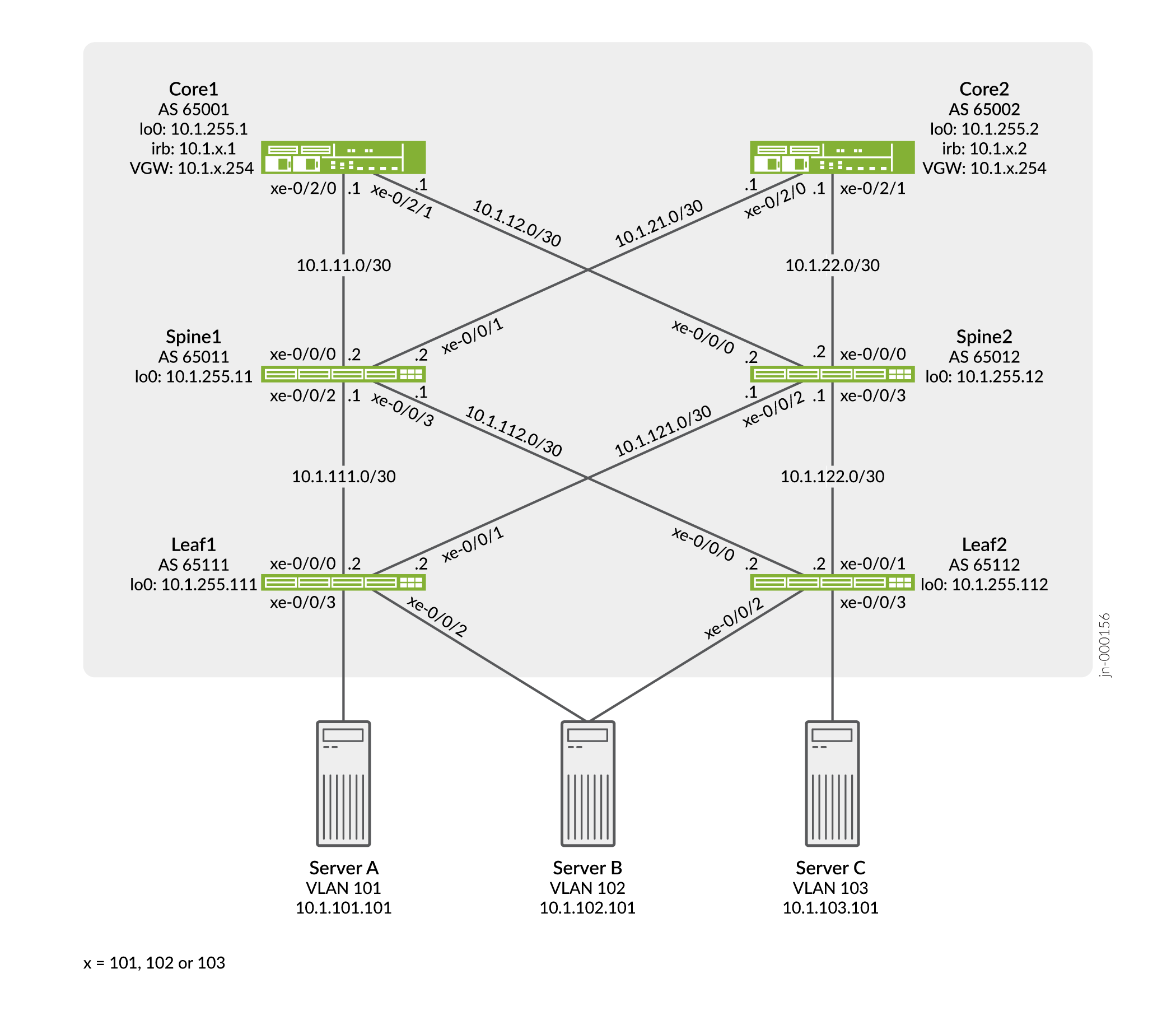
In our sample topology we demonstrate server access using both untagged and trunked (tagged) interfaces. A trunk interface uses explicit VLAN tagging. Both server A and C are configured for trunking while server B uses an untagged access interface to both leaves.
Configuration
CLI Quick Configuration
To quickly configure this example, copy the following commands, paste them into a
text file, remove any line breaks, change any details necessary to match your
network configuration, and then copy and paste the commands into the CLI at the
[edit] hierarchy level.
Leaf-1
set system host-name leaf-1
set chassis aggregated-devices ethernet device-count 2
set interfaces xe-0/0/0 unit 0 family inet address 10.1.111.2/30
set interfaces xe-0/0/1 unit 0 family inet address 10.1.121.2/30
set interfaces xe-0/0/2 ether-options 802.3ad ae0
set interfaces xe-0/0/3 unit 0 family ethernet-switching interface-mode trunk
set interfaces xe-0/0/3 unit 0 family ethernet-switching vlan members v101
set interfaces ae0 esi 00:01:01:01:01:01:01:01:01:01
set interfaces ae0 esi all-active
set interfaces ae0 aggregated-ether-options lacp active
set interfaces ae0 aggregated-ether-options lacp system-id 00:00:00:01:01:01
set interfaces ae0 unit 0 family ethernet-switching interface-mode access
set interfaces ae0 unit 0 family ethernet-switching vlan members v102
set interfaces lo0 unit 0 family inet address 10.1.255.111/32
set policy-options policy-statement lo0 from family inet
set policy-options policy-statement lo0 from protocol direct
set policy-options policy-statement lo0 from route-filter 0.0.0.0/0 prefix-length-range /32-/32
set policy-options policy-statement lo0 then accept
set policy-options policy-statement load-balance term 1 then load-balance per-packet
set policy-options policy-statement vrf-imp term t1 from community com101
set policy-options policy-statement vrf-imp term t1 then accept
set policy-options policy-statement vrf-imp term t2 from community com102
set policy-options policy-statement vrf-imp term t2 then accept
set policy-options policy-statement vrf-imp term t3 from community com103
set policy-options policy-statement vrf-imp term t3 then accept
set policy-options policy-statement vrf-imp term t5 then reject
set policy-options community com101 members target:65000:101
set policy-options community com102 members target:65000:102
set policy-options community com103 members target:65000:103
set routing-options router-id 10.1.255.111
set routing-options autonomous-system 65000
set routing-options forwarding-table export load-balance
set routing-options forwarding-table ecmp-fast-reroute
set protocols bgp group underlay type external
set protocols bgp group underlay export lo0
set protocols bgp group underlay local-as 65111
set protocols bgp group underlay multipath multiple-as
set protocols bgp group underlay neighbor 10.1.111.1 peer-as 65011
set protocols bgp group underlay neighbor 10.1.121.1 peer-as 65012
set protocols bgp group EVPN_VXLAN_CORE type internal
set protocols bgp group EVPN_VXLAN_CORE local-address 10.1.255.111
set protocols bgp group EVPN_VXLAN_CORE family evpn signaling
set protocols bgp group EVPN_VXLAN_CORE neighbor 10.1.255.1
set protocols bgp group EVPN_VXLAN_CORE neighbor 10.1.255.2
set protocols evpn encapsulation vxlan
set protocols evpn multicast-mode ingress-replication
set protocols evpn vni-options vni 101 vrf-target target:65000:101
set protocols evpn vni-options vni 102 vrf-target target:65000:102
set protocols evpn extended-vni-list 101
set protocols evpn extended-vni-list 102
set switch-options vtep-source-interface lo0.0
set switch-options route-distinguisher 10.1.255.111:1
set switch-options vrf-import vrf-imp
set switch-options vrf-target target:65000:1
set vlans v101 vlan-id 101
set vlans v101 vxlan vni 101
set vlans v102 vlan-id 102
set vlans v102 vxlan vni 102
Leaf-2
set system host-name leaf-2
set chassis aggregated-devices ethernet device-count 2
set interfaces xe-0/0/0 unit 0 family inet address 10.1.112.2/30
set interfaces xe-0/0/1 unit 0 family inet address 10.1.122.2/30
set interfaces xe-0/0/2 ether-options 802.3ad ae0
set interfaces xe-0/0/3 unit 0 family ethernet-switching interface-mode trunk
set interfaces xe-0/0/3 unit 0 family ethernet-switching vlan members v103
set interfaces ae0 esi 00:01:01:01:01:01:01:01:01:01
set interfaces ae0 esi all-active
set interfaces ae0 aggregated-ether-options lacp active
set interfaces ae0 aggregated-ether-options lacp system-id 00:00:00:01:01:01
set interfaces ae0 unit 0 family ethernet-switching interface-mode access
set interfaces ae0 unit 0 family ethernet-switching vlan members v102
set interfaces lo0 unit 0 family inet address 10.1.255.112/32
set policy-options policy-statement lo0 from family inet
set policy-options policy-statement lo0 from protocol direct
set policy-options policy-statement lo0 from route-filter 0.0.0.0/0 prefix-length-range /32-/32
set policy-options policy-statement lo0 then accept
set policy-options policy-statement load-balance term 1 then load-balance per-packet
set policy-options policy-statement vrf-imp term t1 from community com101
set policy-options policy-statement vrf-imp term t1 then accept
set policy-options policy-statement vrf-imp term t2 from community com102
set policy-options policy-statement vrf-imp term t2 then accept
set policy-options policy-statement vrf-imp term t3 from community com103
set policy-options policy-statement vrf-imp term t3 then accept
set policy-options policy-statement vrf-imp term t5 then reject
set policy-options community com101 members target:65000:101
set policy-options community com102 members target:65000:102
set policy-options community com103 members target:65000:103
set routing-options router-id 10.1.255.112
set routing-options autonomous-system 65000
set routing-options forwarding-table export load-balance
set routing-options forwarding-table ecmp-fast-reroute
set protocols bgp group underlay type external
set protocols bgp group underlay export lo0
set protocols bgp group underlay local-as 65112
set protocols bgp group underlay multipath multiple-as
set protocols bgp group underlay neighbor 10.1.112.1 peer-as 65011
set protocols bgp group underlay neighbor 10.1.122.1 peer-as 65012
set protocols bgp group EVPN_VXLAN_CORE type internal
set protocols bgp group EVPN_VXLAN_CORE local-address 10.1.255.112
set protocols bgp group EVPN_VXLAN_CORE family evpn signaling
set protocols bgp group EVPN_VXLAN_CORE neighbor 10.1.255.1
set protocols bgp group EVPN_VXLAN_CORE neighbor 10.1.255.2
set protocols evpn encapsulation vxlan
set protocols evpn multicast-mode ingress-replication
set protocols evpn vni-options vni 102 vrf-target target:65000:102
set protocols evpn vni-options vni 103 vrf-target target:65000:103
set protocols evpn extended-vni-list 102
set protocols evpn extended-vni-list 103
set switch-options vtep-source-interface lo0.0
set switch-options route-distinguisher 10.1.255.112:1
set switch-options vrf-import vrf-imp
set switch-options vrf-target target:65000:1
set vlans v102 vlan-id 102
set vlans v102 vxlan vni 102
set vlans v103 vlan-id 103
set vlans v103 vxlan vni 103
Spine-1
set system host-name spine-1
set interfaces xe-0/0/0 unit 0 family inet address 10.1.11.2/30
set interfaces xe-0/0/1 unit 0 family inet address 10.1.21.2/30
set interfaces xe-0/0/2 unit 0 family inet address 10.1.111.1/30
set interfaces xe-0/0/3 unit 0 family inet address 10.1.112.1/30
set interfaces lo0 unit 0 family inet address 10.1.255.11/32
set policy-options policy-statement lo0 from family inet
set policy-options policy-statement lo0 from protocol direct
set policy-options policy-statement lo0 from route-filter 0.0.0.0/0 prefix-length-range /32-/32
set policy-options policy-statement lo0 then accept
set policy-options policy-statement load-balance term 1 then load-balance per-packet
set routing-options router-id 10.1.255.11
set routing-options autonomous-system 65000
set routing-options forwarding-table export load-balance
set routing-options forwarding-table ecmp-fast-reroute
set protocols bgp group underlay type external
set protocols bgp group underlay export lo0
set protocols bgp group underlay local-as 65011
set protocols bgp group underlay multipath multiple-as
set protocols bgp group underlay neighbor 10.1.11.1 peer-as 65001
set protocols bgp group underlay neighbor 10.1.21.1 peer-as 65002
set protocols bgp group underlay neighbor 10.1.111.2 peer-as 65111
set protocols bgp group underlay neighbor 10.1.112.2 peer-as 65112
Spine-2
set system host-name spine-2
set interfaces xe-0/0/0 unit 0 family inet address 10.1.12.2/30
set interfaces xe-0/0/1 unit 0 family inet address 10.1.22.2/30
set interfaces xe-0/0/2 unit 0 family inet address 10.1.121.1/30
set interfaces xe-0/0/3 unit 0 family inet address 10.1.122.1/30
set interfaces lo0 unit 0 family inet address 10.1.255.12/32
set policy-options policy-statement lo0 from family inet
set policy-options policy-statement lo0 from protocol direct
set policy-options policy-statement lo0 from route-filter 0.0.0.0/0 prefix-length-range /32-/32
set policy-options policy-statement lo0 then accept
set policy-options policy-statement load-balance term 1 then load-balance per-packet
set routing-options router-id 10.1.255.12
set routing-options autonomous-system 65000
set routing-options forwarding-table export load-balance
set routing-options forwarding-table ecmp-fast-reroute
set protocols bgp group underlay type external
set protocols bgp group underlay export lo0
set protocols bgp group underlay local-as 65012
set protocols bgp group underlay multipath multiple-as
set protocols bgp group underlay neighbor 10.1.12.1 peer-as 65001
set protocols bgp group underlay neighbor 10.1.22.1 peer-as 65002
set protocols bgp group underlay neighbor 10.1.121.2 peer-as 65111
set protocols bgp group underlay neighbor 10.1.122.2 peer-as 65112
Core-1
set system host-name core-1
set interfaces xe-0/2/0 unit 0 family inet address 10.1.11.1/30
set interfaces xe-0/2/1 unit 0 family inet address 10.1.12.1/30
set interfaces irb unit 101 virtual-gateway-accept-data
set interfaces irb unit 101 family inet address 10.1.101.1/24 virtual-gateway-address 10.1.101.254
set interfaces irb unit 102 virtual-gateway-accept-data
set interfaces irb unit 102 family inet address 10.1.102.1/24 virtual-gateway-address 10.1.102.254
set interfaces irb unit 103 virtual-gateway-accept-data
set interfaces irb unit 103 family inet address 10.1.103.1/24 virtual-gateway-address 10.1.103.254
set interfaces lo0 unit 0 family inet address 10.1.255.1/32
set policy-options policy-statement VS_VLAN101_IMP term ESI from community comm-leaf
set policy-options policy-statement VS_VLAN101_IMP term ESI then accept
set policy-options policy-statement VS_VLAN101_IMP term VS_VLAN101 from community comm-VS_VLAN101
set policy-options policy-statement VS_VLAN101_IMP term VS_VLAN101 then accept
set policy-options policy-statement VS_VLAN102_IMP term ESI from community comm-leaf
set policy-options policy-statement VS_VLAN102_IMP term ESI then accept
set policy-options policy-statement VS_VLAN102_IMP term VS_VLAN102 from community comm-VS_VLAN102
set policy-options policy-statement VS_VLAN102_IMP term VS_VLAN102 then accept
set policy-options policy-statement VS_VLAN103_IMP term ESI from community comm-leaf
set policy-options policy-statement VS_VLAN103_IMP term ESI then accept
set policy-options policy-statement VS_VLAN103_IMP term VS_VLAN103 from community comm-VS_VLAN103
set policy-options policy-statement VS_VLAN103_IMP term VS_VLAN103 then accept
set policy-options policy-statement lo0 from family inet
set policy-options policy-statement lo0 from protocol direct
set policy-options policy-statement lo0 from route-filter 0.0.0.0/0 prefix-length-range /32-/32
set policy-options policy-statement lo0 then accept
set policy-options policy-statement load-balance term 1 then load-balance per-packet
set policy-options community comm-VS_VLAN101 members target:65000:101
set policy-options community comm-VS_VLAN102 members target:65000:102
set policy-options community comm-VS_VLAN103 members target:65000:103
set policy-options community comm-leaf members target:65000:1
set routing-instances VRF_Tenant_A instance-type vrf
set routing-instances VRF_Tenant_A interface irb.101
set routing-instances VRF_Tenant_A route-distinguisher 10.1.255.1:1010
set routing-instances VRF_Tenant_A vrf-target target:65000:101
set routing-instances VRF_Tenant_B instance-type vrf
set routing-instances VRF_Tenant_B interface irb.102
set routing-instances VRF_Tenant_B route-distinguisher 10.1.255.1:1020
set routing-instances VRF_Tenant_B vrf-target target:65000:102
set routing-instances VRF_Tenant_C instance-type vrf
set routing-instances VRF_Tenant_C interface irb.103
set routing-instances VRF_Tenant_C route-distinguisher 10.1.255.1:1030
set routing-instances VRF_Tenant_C vrf-target target:65000:103
set routing-instances VS_VLAN101 instance-type virtual-switch
set routing-instances VS_VLAN101 protocols evpn encapsulation vxlan
set routing-instances VS_VLAN101 protocols evpn extended-vni-list 101
set routing-instances VS_VLAN101 protocols evpn multicast-mode ingress-replication
set routing-instances VS_VLAN101 vtep-source-interface lo0.0
set routing-instances VS_VLAN101 bridge-domains bd101 vlan-id 101
set routing-instances VS_VLAN101 bridge-domains bd101 routing-interface irb.101
set routing-instances VS_VLAN101 bridge-domains bd101 vxlan vni 101
set routing-instances VS_VLAN101 route-distinguisher 10.1.255.1:101
set routing-instances VS_VLAN101 vrf-import VS_VLAN101_IMP
set routing-instances VS_VLAN101 vrf-target target:65000:101
set routing-instances VS_VLAN102 instance-type virtual-switch
set routing-instances VS_VLAN102 protocols evpn encapsulation vxlan
set routing-instances VS_VLAN102 protocols evpn extended-vni-list 102
set routing-instances VS_VLAN102 protocols evpn multicast-mode ingress-replication
set routing-instances VS_VLAN102 vtep-source-interface lo0.0
set routing-instances VS_VLAN102 bridge-domains bd102 vlan-id 102
set routing-instances VS_VLAN102 bridge-domains bd102 routing-interface irb.102
set routing-instances VS_VLAN102 bridge-domains bd102 vxlan vni 102
set routing-instances VS_VLAN102 route-distinguisher 10.1.255.1:102
set routing-instances VS_VLAN102 vrf-import VS_VLAN102_IMP
set routing-instances VS_VLAN102 vrf-target target:65000:102
set routing-instances VS_VLAN103 instance-type virtual-switch
set routing-instances VS_VLAN103 protocols evpn encapsulation vxlan
set routing-instances VS_VLAN103 protocols evpn extended-vni-list 103
set routing-instances VS_VLAN103 protocols evpn multicast-mode ingress-replication
set routing-instances VS_VLAN103 vtep-source-interface lo0.0
set routing-instances VS_VLAN103 bridge-domains bd103 vlan-id 103
set routing-instances VS_VLAN103 bridge-domains bd103 routing-interface irb.103
set routing-instances VS_VLAN103 bridge-domains bd103 vxlan vni 103
set routing-instances VS_VLAN103 route-distinguisher 10.1.255.1:103
set routing-instances VS_VLAN103 vrf-import VS_VLAN103_IMP
set routing-instances VS_VLAN103 vrf-target target:65000:103
set routing-options router-id 10.1.255.1
set routing-options autonomous-system 65000
set routing-options forwarding-table export load-balance
set routing-options forwarding-table ecmp-fast-reroute
set protocols bgp group underlay type external
set protocols bgp group underlay export lo0
set protocols bgp group underlay local-as 65001
set protocols bgp group underlay multipath multiple-as
set protocols bgp group underlay neighbor 10.1.11.2 peer-as 65011
set protocols bgp group underlay neighbor 10.1.12.2 peer-as 65012
set protocols bgp group EVPN_VXLAN type internal
set protocols bgp group EVPN_VXLAN local-address 10.1.255.1
set protocols bgp group EVPN_VXLAN family evpn signaling
set protocols bgp group EVPN_VXLAN cluster 10.1.1.1
set protocols bgp group EVPN_VXLAN multipath
set protocols bgp group EVPN_VXLAN neighbor 10.1.255.111
set protocols bgp group EVPN_VXLAN neighbor 10.1.255.112
set protocols bgp group EVPN_VXLAN neighbor 10.1.255.2
Core-2
set system host-name core-2
set interfaces xe-0/2/0 unit 0 family inet address 10.1.21.1/30
set interfaces xe-0/2/1 unit 0 family inet address 10.1.22.1/30
set interfaces irb unit 101 virtual-gateway-accept-data
set interfaces irb unit 101 family inet address 10.1.101.2/24 virtual-gateway-address 10.1.101.254
set interfaces irb unit 102 virtual-gateway-accept-data
set interfaces irb unit 102 family inet address 10.1.102.2/24 virtual-gateway-address 10.1.102.254
set interfaces irb unit 103 virtual-gateway-accept-data
set interfaces irb unit 103 family inet address 10.1.103.2/24 virtual-gateway-address 10.1.103.254
set interfaces lo0 unit 0 family inet address 10.1.255.2/32
set policy-options policy-statement VS_VLAN101_IMP term ESI from community comm-leaf
set policy-options policy-statement VS_VLAN101_IMP term ESI then accept
set policy-options policy-statement VS_VLAN101_IMP term VS_VLAN101 from community comm-VS_VLAN101
set policy-options policy-statement VS_VLAN101_IMP term VS_VLAN101 then accept
set policy-options policy-statement VS_VLAN102_IMP term ESI from community comm-leaf
set policy-options policy-statement VS_VLAN102_IMP term ESI then accept
set policy-options policy-statement VS_VLAN102_IMP term VS_VLAN102 from community comm-VS_VLAN102
set policy-options policy-statement VS_VLAN102_IMP term VS_VLAN102 then accept
set policy-options policy-statement VS_VLAN103_IMP term ESI from community comm-leaf
set policy-options policy-statement VS_VLAN103_IMP term ESI then accept
set policy-options policy-statement VS_VLAN103_IMP term VS_VLAN103 from community comm-VS_VLAN103
set policy-options policy-statement VS_VLAN103_IMP term VS_VLAN103 then accept
set policy-options policy-statement lo0 from family inet
set policy-options policy-statement lo0 from protocol direct
set policy-options policy-statement lo0 from route-filter 0.0.0.0/0 prefix-length-range /32-/32
set policy-options policy-statement lo0 then accept
set policy-options policy-statement load-balance term 1 then load-balance per-packet
set policy-options community comm-VS_VLAN101 members target:65000:101
set policy-options community comm-VS_VLAN102 members target:65000:102
set policy-options community comm-VS_VLAN103 members target:65000:103
set policy-options community comm-leaf members target:65000:1
set routing-instances VRF_Tenant_A instance-type vrf
set routing-instances VRF_Tenant_A interface irb.101
set routing-instances VRF_Tenant_A route-distinguisher 10.1.255.2:1010
set routing-instances VRF_Tenant_A vrf-target target:65000:101
set routing-instances VRF_Tenant_B instance-type vrf
set routing-instances VRF_Tenant_B interface irb.102
set routing-instances VRF_Tenant_B route-distinguisher 10.1.255.2:1020
set routing-instances VRF_Tenant_B vrf-target target:65000:102
set routing-instances VRF_Tenant_C instance-type vrf
set routing-instances VRF_Tenant_C interface irb.103
set routing-instances VRF_Tenant_C route-distinguisher 10.1.255.2:1030
set routing-instances VRF_Tenant_C vrf-target target:65000:103
set routing-instances VS_VLAN101 instance-type virtual-switch
set routing-instances VS_VLAN101 protocols evpn encapsulation vxlan
set routing-instances VS_VLAN101 protocols evpn extended-vni-list 101
set routing-instances VS_VLAN101 protocols evpn multicast-mode ingress-replication
set routing-instances VS_VLAN101 vtep-source-interface lo0.0
set routing-instances VS_VLAN101 bridge-domains bd101 vlan-id 101
set routing-instances VS_VLAN101 bridge-domains bd101 routing-interface irb.101
set routing-instances VS_VLAN101 bridge-domains bd101 vxlan vni 101
set routing-instances VS_VLAN101 route-distinguisher 10.1.255.2:101
set routing-instances VS_VLAN101 vrf-import VS_VLAN101_IMP
set routing-instances VS_VLAN101 vrf-target target:65000:101
set routing-instances VS_VLAN102 instance-type virtual-switch
set routing-instances VS_VLAN102 protocols evpn encapsulation vxlan
set routing-instances VS_VLAN102 protocols evpn extended-vni-list 102
set routing-instances VS_VLAN102 protocols evpn multicast-mode ingress-replication
set routing-instances VS_VLAN102 vtep-source-interface lo0.0
set routing-instances VS_VLAN102 bridge-domains bd102 vlan-id 102
set routing-instances VS_VLAN102 bridge-domains bd102 routing-interface irb.102
set routing-instances VS_VLAN102 bridge-domains bd102 vxlan vni 102
set routing-instances VS_VLAN102 route-distinguisher 10.1.255.2:102
set routing-instances VS_VLAN102 vrf-import VS_VLAN102_IMP
set routing-instances VS_VLAN102 vrf-target target:65000:102
set routing-instances VS_VLAN103 instance-type virtual-switch
set routing-instances VS_VLAN103 protocols evpn encapsulation vxlan
set routing-instances VS_VLAN103 protocols evpn extended-vni-list 103
set routing-instances VS_VLAN103 protocols evpn multicast-mode ingress-replication
set routing-instances VS_VLAN103 vtep-source-interface lo0.0
set routing-instances VS_VLAN103 bridge-domains bd103 vlan-id 103
set routing-instances VS_VLAN103 bridge-domains bd103 routing-interface irb.103
set routing-instances VS_VLAN103 bridge-domains bd103 vxlan vni 103
set routing-instances VS_VLAN103 route-distinguisher 10.1.255.2:103
set routing-instances VS_VLAN103 vrf-import VS_VLAN103_IMP
set routing-instances VS_VLAN103 vrf-target target:65000:103
set routing-options router-id 10.1.255.2
set routing-options autonomous-system 65000
set routing-options forwarding-table export load-balance
set routing-options forwarding-table ecmp-fast-reroute
set protocols bgp group underlay type external
set protocols bgp group underlay export lo0
set protocols bgp group underlay local-as 65002
set protocols bgp group underlay multipath multiple-as
set protocols bgp group underlay neighbor 10.1.21.2 peer-as 65011
set protocols bgp group underlay neighbor 10.1.22.2 peer-as 65012
set protocols bgp group EVPN_VXLAN type internal
set protocols bgp group EVPN_VXLAN local-address 10.1.255.2
set protocols bgp group EVPN_VXLAN family evpn signaling
set protocols bgp group EVPN_VXLAN cluster 10.2.2.2
set protocols bgp group EVPN_VXLAN multipath
set protocols bgp group EVPN_VXLAN neighbor 10.1.255.111
set protocols bgp group EVPN_VXLAN neighbor 10.1.255.112
set protocols bgp group EVPN_VXLAN neighbor 10.1.255.1
EX9200 Configuration
On EX9200 switches, the vlans statement is used instead of
bridge-domains, and the l3-interface
statement is used instead of routing-interface.
The following example shows how to configure these statements. All other configuration shown for MX Series routers in this example also applies to EX9200 switches.
set routing-instances VS_VLAN300 vlans vlan1300 vlan-id 300
set routing-instances VS_VLAN300 vlans vlan1300 l3-inteface irb.1300
In this example, wherever bridge-domains or
routing-interface statements are used, to configure on
EX9200 switches, use vlans and
l3-interface instead.
Configuring Leaf-1
Step-by-Step Procedure
The following example requires you to navigate various levels in the configuration hierarchy. For information about navigating the CLI, see Using the CLI Editor in Configuration Mode in the CLI User Guide.
The steps for configuring Leaf-2 are similar to Leaf-1 and therefore we will only show the step-by-step procedures for Leaf-1.
To configure Leaf-1:
-
Set the system hostname.
[edit]
user@leaf-1# set system host-name leaf-1
-
Configure routing options. The load-balance export policy is configured in the next step.
[edit]
user@leaf-1# set routing-options router-id 10.1.255.111
user@leaf-1# set routing-options autonomous-system 65000
user@leaf-1# set routing-options forwarding-table export load-balance
user@leaf-1# set routing-options forwarding-table ecmp-fast-reroute
-
Configure the load balancing policy.
[edit policy-options policy-statement load-balance]
user@leaf-1# set term 1 then load-balance per-packet
-
Configure the underlay EBGP to the spine devices. The lo0 export policy is configured in the next step.
[edit]
user@leaf-1# set protocols bgp group underlay type external
user@leaf-1# set protocols bgp group underlay export lo0
user@leaf-1# set protocols bgp group underlay local-as 65111
user@leaf-1# set protocols bgp group underlay multipath multiple-as
user@leaf-1# set protocols bgp group underlay neighbor 10.1.111.1 peer-as 65011
user@leaf-1# set protocols bgp group underlay neighbor 10.1.121.1 peer-as 65012
-
Configure a policy to advertise the loopback address into the underlay. In this example you write a portable policy that is loopback address agnostic, by matching only direct routes with a /32 prefix length. The result is a policy that matches any loopback address and is reusable across all devices in the topology.
[edit policy-options policy-statement lo0]
user@leaf-1# set from family inet
user@leaf-1# set from protocol direct
user@leaf-1# set from route-filter 0.0.0.0/0 prefix-length-range /32-/32
user@leaf-1# set then accept
-
Configure switch options The virtual tunnel endpoint interface is lo0.0, which must be reachable through the underlay routing protocol. The route distinguisher must be unique across all switches in the network to ensure all route advertisements within MP-BGP overlay are globally unique. The VRF table target on the QFX Series switch is, at a minimum, the community the switch sends attaches to all ESI (Type-1) routes. The
vrf-import vrf-impstatement defines the target community list, which is imported into thedefault-switch.evpn.0instance from thebgp.evpn.0table.[edit] user@leaf-1# set switch-options vtep-source-interface lo0.0 user@leaf-1# set switch-options route-distinguisher 10.1.255.111:1 user@leaf-1# set switch-options vrf-import vrf-imp user@leaf-1# set switch-options vrf-target target:65000:1
-
Configure the VRF table import policy.
[edit]
user@leaf-1# set policy-options policy-statement vrf-imp term t1 from community com101
user@leaf-1# set policy-options policy-statement vrf-imp term t1 then accept
user@leaf-1# set policy-options policy-statement vrf-imp term t2 from community com102
user@leaf-1# set policy-options policy-statement vrf-imp term t2 then accept
user@leaf-1# set policy-options policy-statement vrf-imp term t3 from community com103
user@leaf-1# set policy-options policy-statement vrf-imp term t3 then accept
user@leaf-1# set policy-options policy-statement vrf-imp term t5 then reject
-
Configure the related communities.
[edit]
user@leaf-1# set policy-options community com101 members target:65000:101
user@leaf-1# set policy-options community com102 members target:65000:102
user@leaf-1# set policy-options community com103 members target:65000:103
-
Configure the extended virtual network identifier (VNI) list to establish the VNIs you want to be part of the EVPN domain. You also configure ingress replication; in EVPN-VXLAN ingress-replication is used to handle multicast without requiring a multicast capable underlay. Different route targets are specified for each VXLAN network identifier instance under
vni-routing-options.[edit] user@leaf-1# set protocols evpn encapsulation vxlan user@leaf-1# set protocols evpn multicast-mode ingress-replication user@leaf-1# set protocols evpn vni-options vni 101 vrf-target target:65000:101 user@leaf-1# set protocols evpn vni-options vni 102 vrf-target target:65000:102 user@leaf-1# set protocols evpn extended-vni-list 101 user@leaf-1# set protocols evpn extended-vni-list 102
-
Map locally significant VLAN IDs to globally significant VXLAN network identifiers.
[edit]
user@leaf-1# set vlans v101 vlan-id 101
user@leaf-1# set vlans v101 vxlan vni 101
user@leaf-1# set vlans v102 vlan-id 102
user@leaf-1# set vlans v102 vxlan vni 102
-
Configure the EVPN capable IBGP overlay sessions.
[edit]
user@leaf-1# set protocols bgp group EVPN_VXLAN_CORE type internal
user@leaf-1# set protocols bgp group EVPN_VXLAN_CORE local-address 10.1.255.111
user@leaf-1# set protocols bgp group EVPN_VXLAN_CORE family evpn signaling
user@leaf-1# set protocols bgp group EVPN_VXLAN_CORE neighbor 10.1.255.1
user@leaf-1# set protocols bgp group EVPN_VXLAN_CORE neighbor 10.1.255.2
Note:Some IP fabrics use an EBGP based EVPN-VXLAN overlay. For an example of an IP fabric that uses EBGP for both the underlay and overlay, see Example: Configuring an EVPN-VXLAN Edge-Routed Bridging Fabric with an Anycast Gateway. Note that the choice of EBGP vs IBGP for the overlay does not impact on the fabric architecture. Both CRB and edge-routed bridging (ERB) designs support either type of overlay.
-
Configure the fabric interfaces.
[edit]
user@leaf-1# set interfaces xe-0/0/0 unit 0 family inet address 10.1.111.2/30
user@leaf-1# set interfaces xe-0/0/1 unit 0 family inet address 10.1.121.2/30
-
Configure the access interfaces. Note again that we demonstrate a mix of access and trunk interfaces for server attachment.
[edit]
user@leaf-1# set interfaces xe-0/0/2 ether-options 802.3ad ae0
user@leaf-1# set interfaces xe-0/0/3 unit 0 family ethernet-switching interface-mode trunk
user@leaf-1# set interfaces xe-0/0/3 unit 0 family ethernet-switching vlan members v101
-
Configure the LACP-enabled LAG interface. The ESI value is globally unique across the entire EVPN domain. The
all-activeconfiguration statement ensures that all PE routers to which this multihomed tenant is attached to can forward traffic from the CE device, such that all CE links are actively used.[edit] user@leaf-1# set interfaces ae0 esi 00:01:01:01:01:01:01:01:01:01 user@leaf-1# set interfaces ae0 esi all-active user@leaf-1# set interfaces ae0 aggregated-ether-options lacp active user@leaf-1# set interfaces ae0 aggregated-ether-options lacp system-id 00:00:00:01:01:01 user@leaf-1# set interfaces ae0 unit 0 family ethernet-switching interface-mode access user@leaf-1# set interfaces ae0 unit 0 family ethernet-switching vlan members v102
-
Configure the loopback interface address.
[edit]
user@leaf-1# set interfaces lo0 unit 0 family inet address 10.1.255.111/32
Configuring Spine-1
Step-by-Step Procedure
The following example requires you to navigate various levels in the configuration hierarchy. For information about navigating the CLI, see Using the CLI Editor in Configuration Mode in the CLI User Guide.
The steps for configuring Spine-2 are similar to Spine-1 and therefore we will only show the step-by-step procedures for Spine-1.
To configure Spine-1:
-
Set the system hostname.
[edit]
user@spine-1# set system host-name spine-1
-
Configure the routing options.
[edit]
user@spine-1# set routing-options router-id 10.1.255.11
user@spine-1# set routing-options autonomous-system 65000
user@spine-1# set routing-options forwarding-table export load-balance
user@spine-1# set routing-options forwarding-table ecmp-fast-reroute
-
Configure a load balancing policy.
[edit policy-options policy-statement load-balance]
user@spine-1# set term 1 then load-balance per-packet
-
Configure the EBGP underlay with peering to the leaf and core devices. The lo0 policy that advertises the lo0 address is applied in this step; the configuration of the policy itself is shown in the next step.
[edit]
user@spine-1# set protocols bgp group underlay type external
user@spine-1# set protocols bgp group underlay export lo0
user@spine-1# set protocols bgp group underlay local-as 65011
user@spine-1# set protocols bgp group underlay multipath multiple-as
user@spine-1# set protocols bgp group underlay neighbor 10.1.11.1 peer-as 65001
user@spine-1# set protocols bgp group underlay neighbor 10.1.21.1 peer-as 65002
user@spine-1# set protocols bgp group underlay neighbor 10.1.111.2 peer-as 65111
user@spine-1# set protocols bgp group underlay neighbor 10.1.112.2 peer-as 65112
-
Configure a policy named lo0 to advertise /32 routes. The policy matches on the loopback address, without specifying any specific IP. In this way the same policy is reusable on any fabric device.
[edit policy-options policy-statement lo0]
user@spine-1# set from family inet
user@spine-1# set from protocol direct
user@spine-1# set from route-filter 0.0.0.0/0 prefix-length-range /32-/32
user@spine-1# set then accept
Configuring Core-1
Step-by-Step Procedure
The following example requires you to navigate various levels in the configuration hierarchy. For information about navigating the CLI, see Using the CLI Editor in Configuration Mode in the CLI User Guide.
The steps for configuring Core-2 are similar to Core-1 and therefore we will only show the step-by-step procedures for Core-1.
To configure Core-1:
-
Set the system hostname.
[edit]
user@core-1# set system host-name core-1
-
Configure the routing options. The load-balance policy is applied during this step. You create the policy in the next step
[edit]
user@core-1# set routing-options router-id 10.1.255.1
user@core-1# set routing-options autonomous-system 65000
user@core-1# set routing-options forwarding-table export load-balance
user@core-1# set routing-options forwarding-table ecmp-fast-reroute
-
Configure a load balancing policy named load-balance.
[edit policy-options policy-statement load-balance]
user@core-1# set term 1 then load-balance per-packet
-
Configure the BGP underlay peering. The lo0 policy that advertises the loopback address is applied during this step. You configure this policy in the next step.
[edit]
user@core-1# set protocols bgp group underlay type external
user@core-1# set protocols bgp group underlay export lo0
user@core-1# set protocols bgp group underlay local-as 65001
user@core-1# set protocols bgp group underlay multipath multiple-as
user@core-1# set protocols bgp group underlay neighbor 10.1.11.2 peer-as 65011
user@core-1# set protocols bgp group underlay neighbor 10.1.12.2 peer-as 65012
-
Configure a policy named
lo0to advertise loopback routes.[edit policy-options policy-statement lo0] user@core-1# set from family inet user@core-1# set from protocol direct user@core-1# set lo0 from route-filter 0.0.0.0/0 prefix-length-range /32-/32 user@core-1# set lo0 then accept
-
A large portion of Core-1’s configuration takes place in the
[routing-instance]hierarchy. Configure the virtual routers and configure a unique VRF table import policy for each virtual switch.[edit] user@core-1# set routing-instances VRF_Tenant_A instance-type vrf user@core-1# set routing-instances VRF_Tenant_A interface irb.101 user@core-1# set routing-instances VRF_Tenant_A route-distinguisher 10.1.255.1:1010 user@core-1# set routing-instances VRF_Tenant_A vrf-target target:65000:101 user@core-1# set routing-instances VRF_Tenant_B instance-type vrf user@core-1# set routing-instances VRF_Tenant_B interface irb.102 user@core-1# set routing-instances VRF_Tenant_B route-distinguisher 10.1.255.1:1020 user@core-1# set routing-instances VRF_Tenant_B vrf-target target:65000:102 user@core-1# set routing-instances VRF_Tenant_C instance-type vrf user@core-1# set routing-instances VRF_Tenant_C interface irb.103 user@core-1# set routing-instances VRF_Tenant_C route-distinguisher 10.1.255.1:1030 user@core-1# set routing-instances VRF_Tenant_C vrf-target target:65000:103 user@core-1# set routing-instances VS_VLAN101 instance-type virtual-switch user@core-1# set routing-instances VS_VLAN101 protocols evpn encapsulation vxlan user@core-1# set routing-instances VS_VLAN101 protocols evpn extended-vni-list 101 user@core-1# set routing-instances VS_VLAN101 protocols evpn multicast-mode ingress-replication user@core-1# set routing-instances VS_VLAN101 vtep-source-interface lo0.0 user@core-1# set routing-instances VS_VLAN101 bridge-domains bd101 vlan-id 101 user@core-1# set routing-instances VS_VLAN101 bridge-domains bd101 routing-interface irb.101 user@core-1# set routing-instances VS_VLAN101 bridge-domains bd101 vxlan vni 101 user@core-1# set routing-instances VS_VLAN101 route-distinguisher 10.1.255.1:101 user@core-1# set routing-instances VS_VLAN101 vrf-import VS_VLAN101_IMP user@core-1# set routing-instances VS_VLAN101 vrf-target target:65000:101 user@core-1# set routing-instances VS_VLAN102 instance-type virtual-switch user@core-1# set routing-instances VS_VLAN102 protocols evpn encapsulation vxlan user@core-1# set routing-instances VS_VLAN102 protocols evpn extended-vni-list 102 user@core-1# set routing-instances VS_VLAN102 protocols evpn multicast-mode ingress-replication user@core-1# set routing-instances VS_VLAN102 vtep-source-interface lo0.0 user@core-1# set routing-instances VS_VLAN102 bridge-domains bd102 vlan-id 102 user@core-1# set routing-instances VS_VLAN102 bridge-domains bd102 routing-interface irb.102 user@core-1# set routing-instances VS_VLAN102 bridge-domains bd102 vxlan vni 102 user@core-1# set routing-instances VS_VLAN102 route-distinguisher 10.1.255.1:102 user@core-1# set routing-instances VS_VLAN102 vrf-import VS_VLAN102_IMP user@core-1# set routing-instances VS_VLAN102 vrf-target target:65000:102 user@core-1# set routing-instances VS_VLAN103 instance-type virtual-switch user@core-1# set routing-instances VS_VLAN103 protocols evpn encapsulation vxlan user@core-1# set routing-instances VS_VLAN103 protocols evpn extended-vni-list 103 user@core-1# set routing-instances VS_VLAN103 protocols evpn multicast-mode ingress-replication user@core-1# set routing-instances VS_VLAN103 vtep-source-interface lo0.0 user@core-1# set routing-instances VS_VLAN103 bridge-domains bd103 vlan-id 103 user@core-1# set routing-instances VS_VLAN103 bridge-domains bd103 routing-interface irb.103 user@core-1# set routing-instances VS_VLAN103 bridge-domains bd103 vxlan vni 103 user@core-1# set routing-instances VS_VLAN103 route-distinguisher 10.1.255.1:103 user@core-1# set routing-instances VS_VLAN103 vrf-import VS_VLAN103_IMP user@core-1# set routing-instances VS_VLAN103 vrf-target target:65000:103
-
Configure the policy for each routing instance.
[edit policy-options]
user@core-1# set policy-statement VS_VLAN101_IMP term ESI from community comm-leaf
user@core-1# set policy-statement VS_VLAN101_IMP term ESI then accept
user@core-1# set policy-statement VS_VLAN101_IMP term VS_VLAN101 from community comm-VS_VLAN101
user@core-1# set policy-statement VS_VLAN101_IMP term VS_VLAN101 then accept
user@core-1# set policy-statement VS_VLAN102_IMP term ESI from community comm-leaf
user@core-1# set policy-statement VS_VLAN102_IMP term ESI then accept
user@core-1# set policy-statement VS_VLAN102_IMP term VS_VLAN102 from community comm-VS_VLAN102
user@core-1# set policy-statement VS_VLAN102_IMP term VS_VLAN102 then accept
user@core-1# set policy-statement VS_VLAN103_IMP term ESI from community comm-leaf
user@core-1# set policy-statement VS_VLAN103_IMP term ESI then accept
user@core-1# set policy-statement VS_VLAN103_IMP term VS_VLAN103 from community comm-VS_VLAN103
user@core-1# set policy-statement VS_VLAN103_IMP term VS_VLAN103 then accept
-
Configure the communities . Make sure that the comm-leaf policy accepts routes tagged with target 65000:1. This ensures that all virtual switches import the Type-1 ESI routes from all leafs.
[edit]
user@core-1# set policy-options community comm-VS_VLAN101 members target:65000:101
user@core-1# set policy-options community comm-VS_VLAN102 members target:65000:102
user@core-1# set policy-options community comm-VS_VLAN103 members target:65000:103
user@core-1# set policy-options community comm-leaf members target:65000:1
-
Configure the IRB interfaces. Every IRB has a virtual gateway address, which is a shared MAC address and IP address across Core-1 and Core-2.
[edit interfaces irb]
user@core-1# set unit 101 virtual-gateway-accept-data
user@core-1# set unit 101 family inet address 10.1.101.1/24 virtual-gateway-address 10.1.101.254
user@core-1# set unit 102 virtual-gateway-accept-data
user@core-1# set unit 102 family inet address 10.1.102.1/24 virtual-gateway-address 10.1.102.254
user@core-1# set unit 103 virtual-gateway-accept-data
user@core-1# set unit 103 family inet address 10.1.103.1/24 virtual-gateway-address 10.1.103.254
-
Configure the IBGP overlay sessions towards Leaf-1 and Leaf-2. We've include a peering between the Core devices for route sharing between Core devices.
[edit]
user@core-1# set protocols bgp group EVPN_VXLAN type internal
user@core-1# set protocols bgp group EVPN_VXLAN local-address 10.1.255.1
user@core-1# set protocols bgp group EVPN_VXLAN family evpn signaling
user@core-1# set protocols bgp group EVPN_VXLAN cluster 10.1.1.1
user@core-1# set protocols bgp group EVPN_VXLAN multipath
user@core-1# set protocols bgp group EVPN_VXLAN neighbor 10.1.255.111
user@core-1# set protocols bgp group EVPN_VXLAN neighbor 10.1.255.112
user@core-1# set protocols bgp group EVPN_VXLAN neighbor 10.1.255.2
Verification
- Verifying MAC Reachability to a Single-Homed CE Device (Leaf-1)
- Verifying MAC Reachability to a Single-Homed CE Device (Type-2)
- Verifying Imported Routes
- Verifying the Layer 2 Address Learning Daemon Copy
- Verifying the Kernel-Level Forwarding Table
- Verifying MAC Reachability to a Multihomed CE Device
- Verifying EVPN, Layer 2 Address Learning Daemon, and the Kernel-Forwarding Tables for Multihomed CE Device
Verifying MAC Reachability to a Single-Homed CE Device (Leaf-1)
Purpose
Verify MAC reachability to Tenant_A. This user is single-homed to Leaf-1. First, verify that the MAC address is learned locally on Leaf-1. Leaf-1 generates the Type-2 EVPN route only after it learns the MAC address.
Action
Verify that the MAC address is learned locally on Leaf-1.
lab@leaf-1> show ethernet-switching table vlan-id 101

MAC flags (S - static MAC, D - dynamic MAC, L - locally learned, P - Persistent static
           SE - statistics enabled, NM - non configured MAC, R - remote PE MAC, O - ovsdb MAC)


Ethernet switching table : 4 entries, 4 learned
Routing instance : default-switch
   Vlan                MAC                 MAC      Logical                SVLBNH/      Active
   name                address             flags    interface              VENH Index   source
   v101                00:00:5e:00:01:01   DRP      esi.1749                            05:00:00:fd:e8:00:00:00:65:00
   v101                2c:6b:f5:54:95:f0   DR       vtep.32770                          10.1.255.2
   v101                2c:6b:f5:ef:73:f0   DR       vtep.32769                          10.1.255.1
   v101                56:04:15:00:bb:02   D        xe-0/0/3.0
Meaning
The output shows that MAC 56:04:15:00:bb:02 is successfully learned from the Tenant_A CE device, which is Server A on the xe-0/0/3.0 interface.
Verifying MAC Reachability to a Single-Homed CE Device (Type-2)
Purpose
Verify MAC reachability to a single-homed CE device (Type-2)
Action
Verify the generation of the Type-2 route to Core-1.
lab@leaf-1> show route advertising-protocol bgp 10.1.255.1 evpn-mac-address 56:04:15:00:bb:02

bgp.evpn.0: 50 destinations, 91 routes (50 active, 0 holddown, 0 hidden)
  Prefix                  Nexthop              MED     Lclpref    AS path
  2:10.1.255.111:1::101::56:04:15:00:bb:02/304 MAC/IP
*                         Self                         100        I
  2:10.1.255.111:1::101::56:04:15:00:bb:02::10.1.101.101/304 MAC/IP
*                         Self                         100        I

default-switch.evpn.0: 47 destinations, 87 routes (47 active, 0 holddown, 0 hidden)
  Prefix                  Nexthop              MED     Lclpref    AS path
  2:10.1.255.111:1::101::56:04:15:00:bb:02/304 MAC/IP
*                         Self                         100        I
  2:10.1.255.111:1::101::56:04:15:00:bb:02::10.1.101.101/304 MAC/IP
*                         Self                         100        I

__default_evpn__.evpn.0: 3 destinations, 4 routes (3 active, 0 holddown, 0 hidden)
Meaning
The output shows that the MAC and MAC/IP are being advertised.
On Core-1, the
EVPN
Type-2 route is received
into
bgp.evpn.0.
lab@core-1> show route receive-protocol bgp 10.1.255.111 evpn-mac-address 56:04:15:00:bb:02 extensive table bgp.evpn.0

bgp.evpn.0: 52 destinations, 68 routes (52 active, 0 holddown, 0 hidden)
* 2:10.1.255.111:1::101::56:04:15:00:bb:02/304 MAC/IP (2 entries, 1 announced)
     Import Accepted
     Route Distinguisher: 10.1.255.111:1
     Route Label: 101
     ESI: 00:00:00:00:00:00:00:00:00:00
     Nexthop: 10.1.255.111
     Localpref: 100
     AS path: I
     Communities: target:65000:101 encapsulation:vxlan(0x8)

* 2:10.1.255.111:1::101::56:04:15:00:bb:02::10.1.101.101/304 MAC/IP (2 entries, 1 announced)
     Import Accepted
     Route Distinguisher: 10.1.255.111:1
     Route Label: 101
     ESI: 00:00:00:00:00:00:00:00:00:00
     Nexthop: 10.1.255.111
     Localpref: 100
     AS path: I
     Communities: target:65000:101 encapsulation:vxlan(0x8)
The output shows the Type-2 routes for 56:04:15:00:bb:02. The route distinguisher is from Leaf-1 and is set to 10.1.255.111:1.
Verifying Imported Routes
Purpose
Verify that the EVPN Type-2 route is imported.
Action
On Core-1, verify whether EVPN Type-2 routes are successfully imported from
the bgp.evpn.0 table into the EVPN switch instance.
Meaning
The output shows that, in Tenant_A's virtual switch, the
EVPN
Type-2 route is advertised with the correct target,
target:1:101. Use the extensive option to review the Type-2
route in greater detail.
lab@core-1> show route table VS_VLAN101.evpn.0 evpn-mac-address 56:04:15:00:bb:02

VS_VLAN101.evpn.0: 18 destinations, 25 routes (18 active, 0 holddown, 0 hidden)
+ = Active Route, - = Last Active, * = Both

2:10.1.255.111:1::101::56:04:15:00:bb:02/304 MAC/IP
                   *[BGP/170] 1w1d 20:50:01, localpref 100, from 10.1.255.111
                      AS path: I, validation-state: unverified
                    >  to 10.1.11.2 via xe-0/2/0.0
                    [BGP/170] 3d 02:56:43, localpref 100, from 10.1.255.2
                      AS path: I, validation-state: unverified
                    >  to 10.1.11.2 via xe-0/2/0.0
2:10.1.255.111:1::101::56:04:15:00:bb:02::10.1.101.101/304 MAC/IP
                   *[BGP/170] 1w1d 20:50:01, localpref 100, from 10.1.255.111
                      AS path: I, validation-state: unverified
                    >  to 10.1.11.2 via xe-0/2/0.0
                    [BGP/170] 3d 02:56:43, localpref 100, from 10.1.255.2
                      AS path: I, validation-state: unverified
                    >  to 10.1.11.2 via xe-0/2/0.0
The output shows that Core-1 receives two copies. The first is the advertisement from Leaf-1 (Source: 10.1.255.111). The second is the advertisement from Core-2 (Source: 10.1.255.2).
Verifying the Layer 2 Address Learning Daemon Copy
Purpose
Verify the Layer 2 address learning daemon copy.
Action
Verify the Layer 2 address learning daemon copy by entering the show
bridge-mac table command.
Meaning
The output shows that 56:04:15:00:bb:02 is reachable through the vtep.32771 logical interface to Leaf-1.
lab@core-1> show bridge mac-table instance VS_VLAN101
MAC flags       (S -static MAC, D -dynamic MAC, L -locally learned, C -Control MAC
    O -OVSDB MAC, SE -Statistics enabled, NM -Non configured MAC, R -Remote PE MAC, P -Pinned MAC, FU - Fast Update)

Routing instance : VS_VLAN101
 Bridging domain : bd101, VLAN : 101
   MAC                 MAC      Logical                Active
   address             flags    interface              source
   00:00:5e:00:01:01   DRP      esi.722                05:00:00:fd:e8:00:00:00:65:00
   2c:6b:f5:54:95:f0   DR       vtep.32779             10.1.255.2
   56:04:15:00:bb:02   DR       vtep.32771             10.1.255.111
On EX9200 switches, the show ethernet-switching table-instance
instance-name
command corresponds to
the show bridge mac-table instance
instance-name
command used here for
MX Series routers
Verifying the Kernel-Level Forwarding Table
Purpose
Verify the kernel-level forwarding table, next hop identifier, and Layer 2 MAC table and hardware.
Action
Query the kernel-level forwarding table, correlate the index next hop identifier with the correct virtual network identifier, and review the Layer 2 MAC table and hardware.
Meaning
Tenant_A’s MAC, 56:04:15:00:bb:02, is reachable through index 687.
lab@core-1> show route forwarding-table family bridge vpn VS_VLAN101
Routing table: VS_VLAN101.evpn-vxlan
VPLS:
Destination        Type RtRef Next hop           Type Index    NhRef Netif
default            perm     0                    dscd      664     1
vtep.32771         intf     0                    comp      687     7
vtep.32774         intf     0                    comp      691     4
vtep.32779         intf     0                    comp      716     7

Routing table: VS_VLAN101.evpn-vxlan
Bridging domain: bd101.evpn-vxlan
VPLS:
Enabled protocols: Bridging, ACKed by all peers, EVPN VXLAN,
Destination        Type RtRef Next hop           Type Index    NhRef Netif
00:00:5e:00:01:01/48 user     0                  indr  1048579     2
                                                 comp      722     2
2c:6b:f5:54:95:f0/48 user     0                  comp      716     7
56:04:15:00:bb:02/48 user     0                  comp      687     7
0x30003/51         user     0                    comp      705     2
Correlate index 687 (NH-Id) with the correct virtual network identifier 101 and remote VTEP-ID of 10.1.255.111.
lab@core-1> show l2-learning vxlan-tunnel-end-point remote
Logical System Name       Id  SVTEP-IP         IFL   L3-Idx    SVTEP-Mode    ELP-SVTEP-IP
<default>                 0   10.1.255.1       lo0.0    0
 RVTEP-IP         L2-RTT                   IFL-Idx   Interface    NH-Id   RVTEP-Mode  ELP-IP        Flags
 10.1.255.2       VS_VLAN101               377       vtep.32779   716     RNVE
    VNID          MC-Group-IP
    101           0.0.0.0
 RVTEP-IP         L2-RTT                   IFL-Idx   Interface    NH-Id   RVTEP-Mode  ELP-IP        Flags
 10.1.255.111     VS_VLAN101               369       vtep.32771   687     RNVE
    VNID          MC-Group-IP
    101           0.0.0.0
 RVTEP-IP         L2-RTT                   IFL-Idx   Interface    NH-Id   RVTEP-Mode  ELP-IP        Flags
 10.1.255.112     VS_VLAN101               372       vtep.32774   691     RNVE
 10.1.255.2       VS_VLAN102               376       vtep.32778   715     RNVE
    VNID          MC-Group-IP
    102           0.0.0.0
 RVTEP-IP         L2-RTT                   IFL-Idx   Interface    NH-Id   RVTEP-Mode  ELP-IP        Flags
 10.1.255.111     VS_VLAN102               370       vtep.32772   688     RNVE
    VNID          MC-Group-IP
    102           0.0.0.0
 RVTEP-IP         L2-RTT                   IFL-Idx   Interface    NH-Id   RVTEP-Mode  ELP-IP        Flags
 10.1.255.112     VS_VLAN102               373       vtep.32775   695     RNVE
    VNID          MC-Group-IP
    102           0.0.0.0
 RVTEP-IP         L2-RTT                   IFL-Idx   Interface    NH-Id   RVTEP-Mode  ELP-IP        Flags
 10.1.255.2       VS_VLAN103               375       vtep.32777   714     RNVE
    VNID          MC-Group-IP
    103           0.0.0.0
 RVTEP-IP         L2-RTT                   IFL-Idx   Interface    NH-Id   RVTEP-Mode  ELP-IP        Flags
 10.1.255.111     VS_VLAN103               371       vtep.32773   689     RNVE
 10.1.255.112     VS_VLAN103               374       vtep.32776   692     RNVE
    VNID          MC-Group-IP
    103           0.0.0.0
On EX9200 switches, the show ethernet-switching command
corresponds to the show l2-learning command show here
for MX Series routers.
Verifying MAC Reachability to a Multihomed CE Device
Purpose
Verify MAC reachability to the multihomed Tenant_B CE device on Leaf-1 and Leaf-2.
Action
Verify that Leaf-1 and Leaf-2 are advertising both Type-1 and Type-2 reachability towards the multihomed CE device.
lab@leaf-1> show ethernet-switching table vlan-id 102

MAC flags (S - static MAC, D - dynamic MAC, L - locally learned, P - Persistent static
           SE - statistics enabled, NM - non configured MAC, R - remote PE MAC, O - ovsdb MAC)


Ethernet switching table : 4 entries, 4 learned
Routing instance : default-switch
   Vlan                MAC                 MAC      Logical                SVLBNH/      Active
   name                address             flags    interface              VENH Index   source
   v102                00:00:5e:00:01:01   DR       esi.1748                            05:00:00:fd:e8:00:00:00:66:00
   v102                2c:6b:f5:43:12:c0   DL       ae0.0
   v102                2c:6b:f5:54:95:f0   D        vtep.32770                          10.1.255.2
   v102                2c:6b:f5:ef:73:f0   D        vtep.32769                          10.1.255.1

lab@leaf-2>
                  show ethernet-switching table vlan-id 102

MAC flags (S - static MAC, D - dynamic MAC, L - locally learned, P - Persistent static
           SE - statistics enabled, NM - non configured MAC, R - remote PE MAC, O - ovsdb MAC)


Ethernet switching table : 4 entries, 4 learned
Routing instance : default-switch
   Vlan                MAC                 MAC      Logical                SVLBNH/      Active
   name                address             flags    interface              VENH Index   source
   v102                00:00:5e:00:01:01   DR       esi.1749                            05:00:00:fd:e8:00:00:00:66:00
   v102                2c:6b:f5:43:12:c0   DR       ae0.0
   v102                2c:6b:f5:54:95:f0   D        vtep.32769                          10.1.255.2
   v102                2c:6b:f5:ef:73:f0   D        vtep.32770                          10.1.255.1
Meaning
The output shows that 2c:6b:f5:43:12:c0 represents the MAC of the Tenant_B attached to Leaf-1 and Leaf-2.
Verifying EVPN, Layer 2 Address Learning Daemon, and the Kernel-Forwarding Tables for Multihomed CE Device
Purpose
Verify the Tenant B’s EVPN table, and Core-1’s Layer 2 address learning daemon table and kernel-forwarding table.
Action
In Core-1, display the Tenant B’s EVPN table.
lab@core-1> show route table VS_VLAN102.evpn.0

VS_VLAN102.evpn.0: 20 destinations, 29 routes (20 active, 0 holddown, 0 hidden)
+ = Active Route, - = Last Active, * = Both

1:10.1.255.2:0::050000fde80000006600::FFFF:FFFF/192 AD/ESI
                   *[BGP/170] 2d 23:43:32, localpref 100, from 10.1.255.2
                      AS path: I, validation-state: unverified
                       to 10.1.11.2 via xe-0/2/0.0
                    >  to 10.1.12.2 via xe-0/2/1.0
1:10.1.255.111:0::010101010101010101::FFFF:FFFF/192 AD/ESI
                   *[BGP/170] 00:14:59, localpref 100, from 10.1.255.111
                      AS path: I, validation-state: unverified
                    >  to 10.1.11.2 via xe-0/2/0.0
                       to 10.1.12.2 via xe-0/2/1.0
                    [BGP/170] 00:14:58, localpref 100, from 10.1.255.2
                      AS path: I, validation-state: unverified
                    >  to 10.1.11.2 via xe-0/2/0.0
                       to 10.1.12.2 via xe-0/2/1.0
1:10.1.255.111:1::010101010101010101::0/192 AD/EVI
                   *[BGP/170] 00:15:00, localpref 100, from 10.1.255.111
                      AS path: I, validation-state: unverified
                    >  to 10.1.11.2 via xe-0/2/0.0
                       to 10.1.12.2 via xe-0/2/1.0
                    [BGP/170] 00:14:59, localpref 100, from 10.1.255.2
                      AS path: I, validation-state: unverified
                    >  to 10.1.11.2 via xe-0/2/0.0
                       to 10.1.12.2 via xe-0/2/1.0
1:10.1.255.112:0::010101010101010101::FFFF:FFFF/192 AD/ESI
                   *[BGP/170] 00:10:13, localpref 100, from 10.1.255.112
                      AS path: I, validation-state: unverified
                       to 10.1.11.2 via xe-0/2/0.0
                    >  to 10.1.12.2 via xe-0/2/1.0
                    [BGP/170] 00:10:13, localpref 100, from 10.1.255.2
                      AS path: I, validation-state: unverified
                       to 10.1.11.2 via xe-0/2/0.0
                    >  to 10.1.12.2 via xe-0/2/1.0
1:10.1.255.112:1::010101010101010101::0/192 AD/EVI
                   *[BGP/170] 00:10:14, localpref 100, from 10.1.255.112
                      AS path: I, validation-state: unverified
                       to 10.1.11.2 via xe-0/2/0.0
                    >  to 10.1.12.2 via xe-0/2/1.0
                    [BGP/170] 00:10:14, localpref 100, from 10.1.255.2
                      AS path: I, validation-state: unverified
                       to 10.1.11.2 via xe-0/2/0.0
                    >  to 10.1.12.2 via xe-0/2/1.0
2:10.1.255.1:102::102::00:00:5e:00:01:01/304 MAC/IP
                   *[EVPN/170] 2d 23:44:03
                       Indirect
2:10.1.255.1:102::102::2c:6b:f5:ef:73:f0/304 MAC/IP
                   *[EVPN/170] 2d 23:44:03
                       Indirect
2:10.1.255.2:102::102::00:00:5e:00:01:01/304 MAC/IP
                   *[BGP/170] 2d 23:43:32, localpref 100, from 10.1.255.2
                      AS path: I, validation-state: unverified
                       to 10.1.11.2 via xe-0/2/0.0
                    >  to 10.1.12.2 via xe-0/2/1.0
2:10.1.255.2:102::102::2c:6b:f5:54:95:f0/304 MAC/IP
                   *[BGP/170] 2d 23:43:32, localpref 100, from 10.1.255.2
                      AS path: I, validation-state: unverified
                    >  to 10.1.11.2 via xe-0/2/0.0
                       to 10.1.12.2 via xe-0/2/1.0
2:10.1.255.111:1::102::2c:6b:f5:43:12:c0/304 MAC/IP
                   *[BGP/170] 00:14:49, localpref 100, from 10.1.255.111
                      AS path: I, validation-state: unverified
                       to 10.1.11.2 via xe-0/2/0.0
                    >  to 10.1.12.2 via xe-0/2/1.0
                    [BGP/170] 00:14:49, localpref 100, from 10.1.255.2
                      AS path: I, validation-state: unverified
                       to 10.1.11.2 via xe-0/2/0.0
                    >  to 10.1.12.2 via xe-0/2/1.0
2:10.1.255.112:1::102::2c:6b:f5:43:12:c0/304 MAC/IP
                   *[BGP/170] 00:09:24, localpref 100, from 10.1.255.112
                      AS path: I, validation-state: unverified
                    >  to 10.1.11.2 via xe-0/2/0.0
                       to 10.1.12.2 via xe-0/2/1.0
                    [BGP/170] 00:09:24, localpref 100, from 10.1.255.2
                      AS path: I, validation-state: unverified
                    >  to 10.1.11.2 via xe-0/2/0.0
                       to 10.1.12.2 via xe-0/2/1.0
2:10.1.255.1:102::102::00:00:5e:00:01:01::10.1.102.254/304 MAC/IP
                   *[EVPN/170] 2d 23:44:03
                       Indirect
2:10.1.255.1:102::102::2c:6b:f5:ef:73:f0::10.1.102.1/304 MAC/IP
                   *[EVPN/170] 2d 23:44:03
                       Indirect
2:10.1.255.2:102::102::00:00:5e:00:01:01::10.1.102.254/304 MAC/IP
                   *[BGP/170] 2d 23:43:32, localpref 100, from 10.1.255.2
                      AS path: I, validation-state: unverified
                    >  to 10.1.11.2 via xe-0/2/0.0
                       to 10.1.12.2 via xe-0/2/1.0
2:10.1.255.2:102::102::2c:6b:f5:54:95:f0::10.1.102.2/304 MAC/IP
                   *[BGP/170] 2d 23:43:32, localpref 100, from 10.1.255.2
                      AS path: I, validation-state: unverified
                    >  to 10.1.11.2 via xe-0/2/0.0
                       to 10.1.12.2 via xe-0/2/1.0
2:10.1.255.112:1::102::2c:6b:f5:43:12:c0::10.1.102.101/304 MAC/IP
                   *[BGP/170] 00:06:19, localpref 100, from 10.1.255.112
                      AS path: I, validation-state: unverified
                    >  to 10.1.11.2 via xe-0/2/0.0
                       to 10.1.12.2 via xe-0/2/1.0
                    [BGP/170] 00:06:18, localpref 100, from 10.1.255.2
                      AS path: I, validation-state: unverified
                    >  to 10.1.11.2 via xe-0/2/0.0
                       to 10.1.12.2 via xe-0/2/1.0
3:10.1.255.1:102::102::10.1.255.1/248 IM
                   *[EVPN/170] 2d 23:45:49
                       Indirect
3:10.1.255.2:102::102::10.1.255.2/248 IM
                   *[BGP/170] 2d 23:44:03, localpref 100, from 10.1.255.2
                      AS path: I, validation-state: unverified
                    >  to 10.1.11.2 via xe-0/2/0.0
                       to 10.1.12.2 via xe-0/2/1.0
3:10.1.255.111:1::102::10.1.255.111/248 IM
                   *[BGP/170] 00:14:58, localpref 100, from 10.1.255.111
                      AS path: I, validation-state: unverified
                    >  to 10.1.11.2 via xe-0/2/0.0
                       to 10.1.12.2 via xe-0/2/1.0
                    [BGP/170] 00:14:58, localpref 100, from 10.1.255.2
                      AS path: I, validation-state: unverified
                    >  to 10.1.11.2 via xe-0/2/0.0
                       to 10.1.12.2 via xe-0/2/1.0
3:10.1.255.112:1::102::10.1.255.112/248 IM
                   *[BGP/170] 00:10:17, localpref 100, from 10.1.255.112
                      AS path: I, validation-state: unverified
                    >  to 10.1.11.2 via xe-0/2/0.0
                       to 10.1.12.2 via xe-0/2/1.0
                    [BGP/170] 00:10:17, localpref 100, from 10.1.255.2
                      AS path: I, validation-state: unverified
                    >  to 10.1.11.2 via xe-0/2/0.0
                       to 10.1.12.2 via xe-0/2/1.0
Display Core-1’s Layer 2 address learning daemon table.
lab@core-1> show bridge mac-table instance VS_VLAN102

MAC flags       (S -static MAC, D -dynamic MAC, L -locally learned, C -Control MAC
    O -OVSDB MAC, SE -Statistics enabled, NM -Non configured MAC, R -Remote PE MAC, P -Pinned MAC, FU - Fast Update)

Routing instance : VS_VLAN102
 Bridging domain : bd102, VLAN : 102
   MAC                 MAC      Logical                Active
   address             flags    interface              source
   00:00:5e:00:01:01   DRP      esi.708                05:00:00:fd:e8:00:00:00:66:00
   2c:6b:f5:43:12:c0   DR       esi.719                00:01:01:01:01:01:01:01:01:01
   2c:6b:f5:54:95:f0   DR       vtep.32772             10.1.255.2
On EX9200 switches, the show ethernet-switching table-instance
instance-name
command corresponds to
the show bridge mac-table instance
instance-name
command show here for
MX Series routers
Display Core-1’s kernel forwarding table.
lab@core-1> show route forwarding-table vpn VS_VLAN102
Routing table: VS_VLAN102.evpn-vxlan
VPLS:
Destination        Type RtRef Next hop           Type Index    NhRef Netif
default            perm     0                    dscd      544     1
vtep.32772         intf     0                    comp      688     7
vtep.32775         intf     0                    comp      716     5
vtep.32778         intf     0                    comp      722     5

Routing table: VS_VLAN102.evpn-vxlan
Bridging domain: bd102.evpn-vxlan
VPLS:
Enabled protocols: Bridging, ACKed by all peers, EVPN VXLAN,
Destination        Type RtRef Next hop           Type Index    NhRef Netif
00:00:5e:00:01:01/48 user     0                  indr  1048574     2
                                                 comp      708     2
2c:6b:f5:43:12:c0/48 user     0                  indr  1048578     3
                                                 comp      719     2
2c:6b:f5:54:95:f0/48 user     0                  comp      688     7
0x30004/51         user     0                    comp      702     2
Meaning
For the Tenant_B CE device, four different routes are listed for ESI 00:01:01:01:01:01:01:01:01:01:
-
1:10.1.255.111:0::010101010101010101::FFFF:FFFF/192 AD/ESI
This per-Ethernet Segment A-D Type-1 EVPN route originated from Leaf-1. The route distinguisher is obtained from global-level
routing-options. Core-1 receives this Type-1 route, originated from Leaf-1, from both Leaf-1 and Leaf-2. -
1:10.1.255.111:1::010101010101010101::0/192 AD/EVI
This is the per-EVI A-D Type-1 EVPN route. The route distinguisher is obtained from the routing instance, or in the case of QFX5100, the
switch-options. Core-1 receives this Type-1 route, originated from Leaf-1, from both Leaf-1 and Leaf-2. -
1:10.1.255.112:0::010101010101010101::FFFF:FFFF/192 AD/ESI
This is the per-Ethernet Segment A-D Type-1 EVPN route originated from Leaf-2. The route distinguisher is obtained from global-level
routing-options. Core-1 receives this Type-1 route, originated from Leaf-2, from both Leaf-2 and Leaf-1. -
1:10.1.255.112:1::010101010101010101::0/192 AD/EVI
This is the per-EVI A-D Type-1 EVPN route. The route distinguisher is obtained from the routing instance, or in the case of QFX5100,
switch-options. Core-1 receives this Type-1 route, originated from Leaf-2, from both Leaf-2 and Leaf-1.
The Type-2 routes for the two physical and one virtual MAC associated with the Tenant_B multihomed CE device are originated as expected.
From the output we cannot yet determine what VTEPs are used to forward to ESI 00:01:01:01:01:01:01:01:01:01. To determine the VTEPS, display the VXLAN tunnel endpoint ESIs.
lab@core-1> show l2-learning vxlan-tunnel-end-point esi
ESI                           RTT                      VLNBH INH     ESI-IFL   LOC-IFL   #RVTEPs
00:01:01:01:01:01:01:01:01:01 VS_VLAN101               718   1048577 esi.718             2      Aliasing
    RVTEP-IP             RVTEP-IFL      VENH     MASK-ID   FLAGS        MAC-COUNT
    10.1.255.112         vtep.32779     723      1         2            0
    10.1.255.111         vtep.32774     714      0         2            0
...
On EX9200 switches, the show ethernet-switching command
corresponds to the show l2-learning command show here
for MX Series routers.
The output shows active load-balancing on the VTEP interfaces to both Leaf-1 and Leaf-2 for the MAC addresses on this ESI, which validates the all-active configuration on Leaf-1 and Leaf-2.