Connecting the QFX10002
Use the following topics to connect external devices and power to the QFX10002:
Connecting the QFX10002 to Ground
You must install the QFX10002 in a restricted-access location and ensure that the chassis is always properly grounded. The QFX10002 has a two-hole protective grounding terminal provided on the chassis. See Figure 1. Under all circumstances, use this grounding connection to ground the chassis. For AC-powered systems, you must also use the grounding wire in the AC power cord along with the two-hole grounding lug connection. This tested system meets or exceeds all applicable EMC regulatory requirements with the two-hole protective grounding terminal.
Ensure a licensed electrician has attached an appropriate cable lug to the grounding cable that your supply. A cable with an incorrectly attached lug can damage the switch (for example, by causing a short circuit).
Mount your switch in the rack or cabinet before attaching the grounding lug to the switch. See Mounting a QFX10002 in a Rack.
Ensure that you have the following parts and tools available:
-
Grounding cable and lug, see QFX10002 Chassis Grounding Cable and Lug Specifications
-
Two 10-32 UNF x .25 in. screws with #10 split-lock washer
-
Two #10 flat washers
-
Phillips (+) number 2 screwdriver
To connect earth ground to a QFX10002:
-
Place the grounding lug, which is attached to the grounding
cable, over the protective earthing terminal on the chassis. See Figure 1.
Figure 1: Connecting a Grounding Cable to the QFX10002
See Also
Connecting a QFX10002 to a Management Ethernet Device
Ensure that you have an appropriate cable available. See Cable Specifications for Console and Management Connections for the QFX Series.
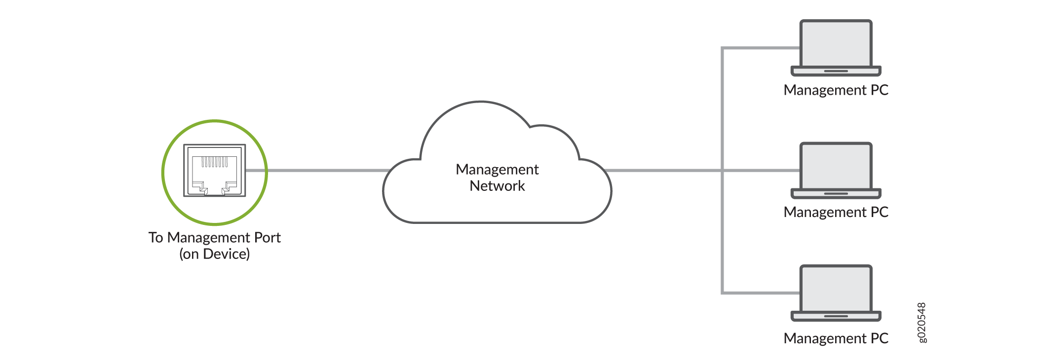
You can monitor and manage the QFX10002 using a dedicated management channel. The QFX10002 has two management ports: a 10/100/1000BASE-T RJ-45 port for copper connections and a 1-Gigabit SFP ports for fiber connections. Use the management ports to connect the QFX10002 to a network for out-of-band management.
You cannot use the management ports to perform the initial configuration of the QFX10002. You must configure the management ports before you can successfully connect to the QFX10002 using these ports. See Performing an Initial Configuration of a QFX10000.
To connect a QFX10002 to a network for out-of-band management (see Figure 2):
- Connect one end of the cable to one of the two management ports (labeled MGMT ) on the QFX10002.
- Connect the other end of the cable to the management switch.
Connecting a QFX Series Device to a Management Console
Ensure that you have an RJ-45 to DB-9 rollover cable available.
- RJ-45 to DB-9 adapter (JNP-CBL-RJ45-DB9)
- RJ-45 to USB-A adapter (JNP-CBL-RJ45-USBA)
- RJ-45 to USB-C adapter (JNP-CBL-RJ45-USBC)
If you want to use RJ-45 to USB-A or RJ-45 to USB-C adapter you must have X64 (64-Bit) Virtual COM port (VCP) driver installed on your PC. See, https://ftdichip.com/drivers/vcp-drivers/ to download the driver.
The QFX Series has a console port with an RJ-45 connector. Use the console port to connect the device to a management console or to a console server.
To connect the QFX Series to a management console (see Figure 3 and Figure 4):
- Connect one end of the Ethernet cable to the console port (labeled CON).
- Connect the other end of the Ethernet cable into the console server (see Figure 3) or management console (see Figure 4).


See Also
Connecting AC Power to a QFX10002
Ensure that you have a power cord appropriate for your geographical location available to connect AC power to the switch.
Before you begin connecting AC power to the switch:
-
Ensure that you have taken the necessary precautions to prevent electrostatic discharge (ESD) damage, (see Prevention of Electrostatic Discharge Damage).
-
Ensure that you have connected the switch chassis to earth ground, see Connecting the QFX10002 to Ground.
-
Install the power supply in the chassis following the instructions in Installing a Power Supply in a QFX10002.
The power supply in a QFX10002 is a hot-removable and hot-insertable field-replaceable unit (FRU). After removing the power cord from an individual power supply, you can remove and replace it without powering off the switch or disrupting switch functions.
Each power supply must be connected to a dedicated power source outlet.
To connect AC power to a QFX10002:
-
Connect each power supply to the power sources. Insert
the coupler end of the power cord into the AC power cord inlet on
the AC power supply faceplate (see Figure 5).
Figure 5: Connecting an AC Power Cord to an AC Power Supply in a QFX10002-72Q
Connecting DC Power to a QFX10002
Before you begin connecting DC power to the switch:
-
Ensure that you have taken the necessary precautions to prevent electrostatic discharge (ESD) damage (see Prevention of Electrostatic Discharge Damage).
-
Ensure that you have connected the switch chassis to earth ground. See Connecting the QFX10002 to Ground.
-
Install the power supply in the chassis. For instructions, follow the instructions in Installing a Power Supply in a QFX10002.
The battery returns of the DC power supply must be connected as an isolated DC return (DC-I).
-
Ensure that you have the following parts and tools available:
-
ESD grounding strap
-
Slotted (–) screwdriver, 1/4-in., with a torque range between 6 lb-in (0.68 Nm) to 7 lb-in (0.79 Nm)
CAUTION:You must use an appropriate torque-controlled tool to tighten the screws on the DC power cable connector. Do not overtighten the screws. Applying excessive torque damages the terminal block and the wiring tray. The absolute maximum torque that may be applied to this screw is 10 lb-in (1.13 Nm).
-
Power cables appropriate for your geographical location available to connect DC power to the QFX10002. There are two types of DC power cables–a straight DC power cable (CBL-JNP-PWR-DSUB) and a right-angle DC power cable (CBL-JNP-PWR-DSUB2) or (CBL-JNP-PWR-DSUB3). See QFX10002 DC Power Specifications.
-
Do not mix AC and DC power supplies in the same chassis.
Each power supply must be connected to a dedicated power source outlet.
The power supply in a QFX10002 is a hot-removable and hot-insertable field-replaceable unit (FRU). You can remove and replace it without powering off the switch or disrupting switch functions. You do, however, need to remove power from the power supply before attempting to remove the unit.
DC-powered QFX10002 models are intended for installation only in a restricted access location.
To connect DC power to a QFX10002:
-
Connect each power supply to the power
source by inserting the DC connector into the power supply. See Figure 6 for straight DC
power cables and Figure 7 and Figure 8 for right-angle
DC power cables.
Figure 6: Connecting a Straight DC Power Cable to a DC Power Supply (CBL-JNP-PWR-DSUB)
 Figure 7: Connecting a Right-Angle DC Power Cable to a DC Power Supply (CBL-JNP-PWR-DSUB2)
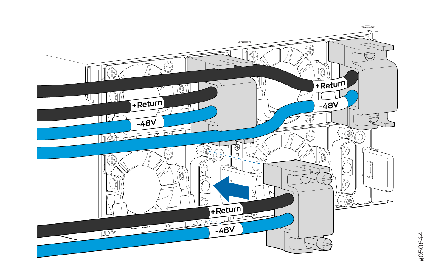 Figure 8: Connecting a Right-Angle DC Power Cable to a DC Power Supply (CBL-JNP-PWR-DSUB3)
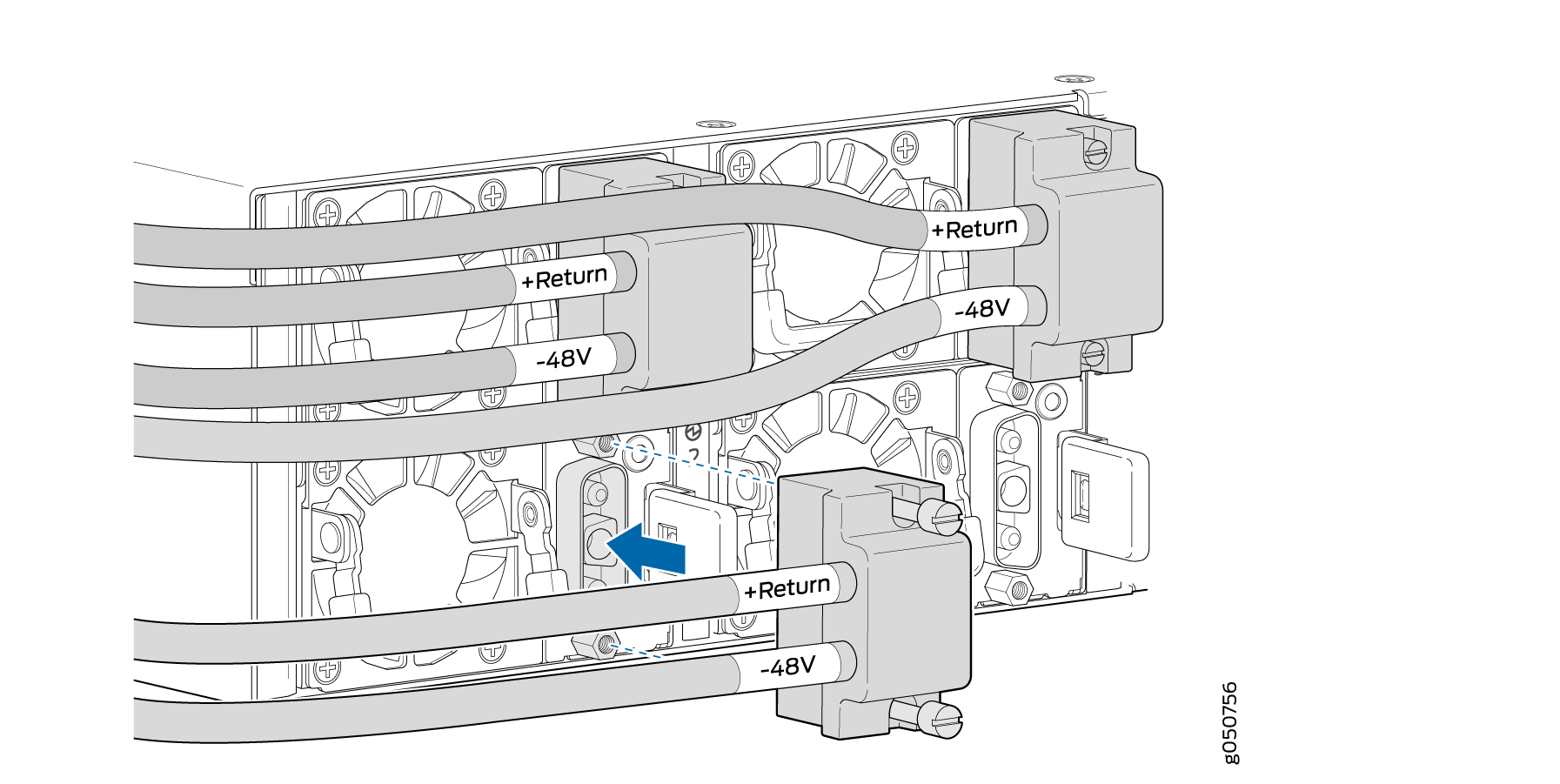 Warning:
Ensure that the power cables do not block access to device components or drape where people can trip on them.