MX480 Interface Modules—DPCs
MX480 Dense Port Concentrator (DPC) Description
A Dense Port Concentrator (DPC) is optimized for Ethernet density (see Figure 1). The DPC assembly combines packet forwarding and Ethernet interfaces on a single board, with either two or four 10-Gbps Packet Forwarding Engines. Each Packet Forwarding Engine consists of one I-chip for Layer 3 processing and one Layer 2 network processor. The DPCs interface with the power supplies and Switch Control Boards (SCBs).
The DPC slots are located in the front of the router (see Figure 1). The router has six dedicated DPC slots that are numbered 0 through 5. A DPC can be installed in any DPC slot on the router. You can install any combination of DPC types in the router. If a slot is not occupied by a DPC, a DPC blank panel must be installed to shield the empty slot and to allow cooling air to circulate properly through the router.
DPCs are hot-removable and hot-insertable, as described in MX480 Field-Replaceable Units (FRUs). When you install a DPC in an operating router, the Routing Engine downloads the DPC software, the DPC runs its diagnostics, and the Packet Forwarding Engines housed on the DPC are enabled. Forwarding on other DPCs continues uninterrupted during this process.
Figure 1 shows typical DPCs supported on the MX480 router. For more information about DPCs, see the MX Series Interface Module Reference .
DPC Components
Each DPC consists of the following components:
-
DPC cover, which functions as a ground plane and a stiffener.
-
Fabric interfaces.
-
Two Gigabit Ethernet interfaces that allow control information, route information, and statistics to be sent between the Routing Engine and the CPU on the DPCs.
-
Two interfaces from the SCBs that enable the DPCs to be powered on and controlled.
-
Physical DPC connectors.
-
Two or four Packet Forwarding Engines.
-
Midplane connectors and power circuitry.
-
Processor subsystem, which includes a 1.2-GHz CPU, system controller, and 1 GB of SDRAM.
-
Online button—Takes the DPC online or offline when pressed.
-
LEDs on the DPC faceplate. For more information about LEDs on the DPC faceplate, see the MX Series Interface Module Reference .
Two LEDs, located on the craft interface above the DPC, display the status of the DPC and are labeled OK and FAIL.
See Also
MX480 DPC Port and Interface Numbering
Each port on a DPC corresponds to a unique interface name in the CLI.
In the syntax of an interface name, a hyphen (-)
separates the media type from the DPC number (represented as an FPC in the CLI). The DPC slot
number corresponds to the first number in the interface. The second
number in the interface corresponds to the logical PIC number. The
last number in the interface matches the port number on the DPC. Slashes
(/) separate the DPC number from the logical PIC number
and port number.
type-fpc/pic/port
-
type—Media type, which identifies the network device. For example:
-
ge—Gigabit Ethernet interface
-
so—SONET/SDH interface
-
xe—10-Gigabit Ethernet interface
For a complete list of media types, see Interface Naming Overview.
-
-
fpc—Slot in which the DPC is installed. On the MX480 router, the DPCs are represented in the CLI as
FPC 0throughFPC 5. -
pic—Logical PIC on the DPC. The number of logical PICs varies depending on the type of DPC. For example, a:
-
20-port Gigabit Ethernet DPC has two logical PICs, numbered 0 through 1.
-
40-port Gigabit Ethernet DPC has four logical PICs, numbered 0 through 3.
-
2-port 10-Gigabit Ethernet DPC has two logical PICs, numbered 0 through 1.
-
4-port 10-Gigabit Ethernet DPC has four logical PICs, numbered 0 through 3.
For more information on specific DPCs, see DPCs Supported on MX240, MX480, and MX960 Routers in the MX Series Interface Module Reference .
-
-
port—Port number.
The MX480 router supports up to six DPCs that install horizontally and are numbered 0 through 5 from bottom to top.
Figure 3 shows a 40-port Gigabit Ethernet DPC with SFP installed in slot 3 on the MX480 router.
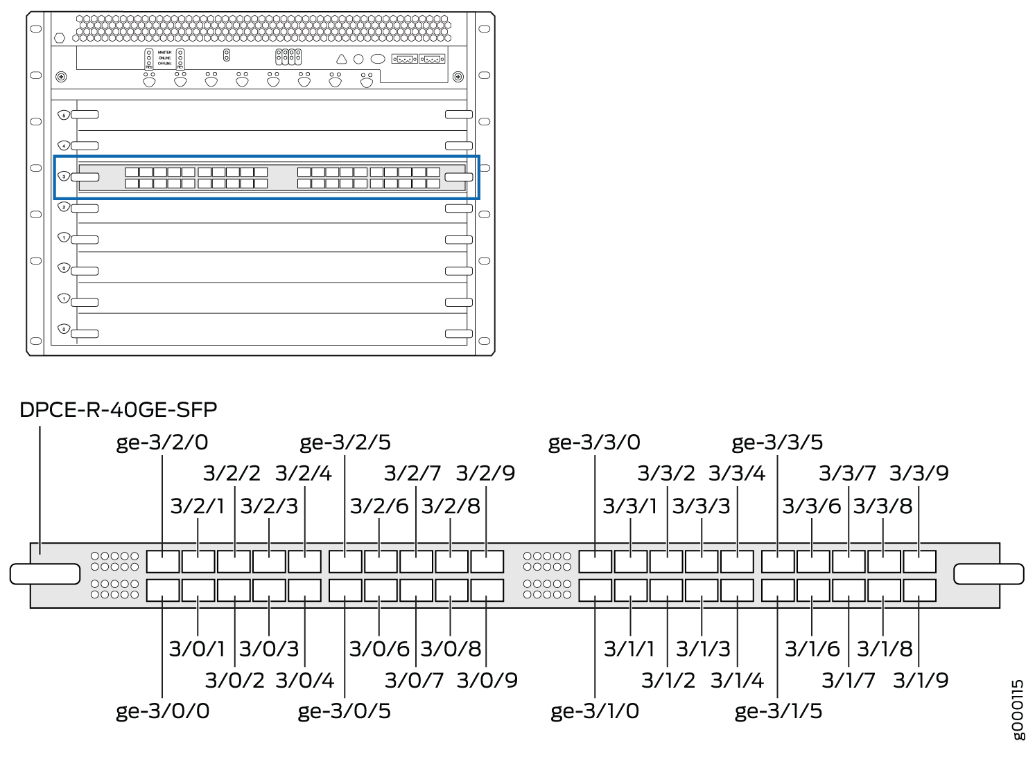
The DPC contains four logical PICs, numbered PIC 0 through PIC 3 in the CLI. Each logical PIC contains 10
ports numbered 0 through 9.
The show chassis hardware command output displays
a 40-port Gigabit Ethernet DPC with SFP (DPCE-R-40GE-SFP) installed in DPC slot 3. The DPC (DPCE 40x 1GE R) is shown as FPC 3 in the CLI. The DPC’s four logical PICs — 10x 1GE(LAN) — are shown as PIC 0 through PIC 3.
user@host> show chassis hardware

...
FPC 3            REV 07   750-018122   KB8222            DPCE 40x 1GE R
  CPU            REV 06   710-013713   KA9010            DPC PMB
  PIC 0                   BUILTIN      BUILTIN           10x 1GE(LAN)
    Xcvr 0       REV 01   740-011782   PCH2NU4           SFP-SX
    Xcvr 1       REV 01   740-011782   PCH2P4R           SFP-SX
    Xcvr 2       REV 01   740-011782   PCH2NYL           SFP-SX
    Xcvr 3       REV 01   740-011782   PCH2UW6           SFP-SX
    Xcvr 4       REV 01   740-011782   PCH2P4N           SFP-SX
    Xcvr 5       REV 01   740-011782   PCH2UME           SFP-SX
    Xcvr 6       REV 01   740-011613   PCE1H5P           SFP-SX
    Xcvr 7       REV 01   740-011782   PCH2UFG           SFP-SX
    Xcvr 8       REV 02   740-011613   AM0947SEYU2       SFP-SX
    Xcvr 9       REV 02   740-011613   AM0947SEYTQ       SFP-SX
  PIC 1                   BUILTIN      BUILTIN           10x 1GE(LAN)
    Xcvr 0       REV 01   740-011782   PCH2UYF           SFP-SX
    Xcvr 1       REV 01   740-011782   PCH2P4L           SFP-SX
    Xcvr 2       REV 01   740-011782   PCH2UCL           SFP-SX
    Xcvr 3       REV 01   740-011782   PCH2P4X           SFP-SX
    Xcvr 4       REV 01   740-011782   PCH2P1E           SFP-SX
    Xcvr 5       REV 01   740-011782   PCH2UD2           SFP-SX
    Xcvr 6       REV 01   740-011782   PCH2PLC           SFP-SX
    Xcvr 7       REV 01   740-011782   PCH2UDJ           SFP-SX
    Xcvr 8       REV 02   740-011613   AM0947SEX7S       SFP-SX
  PIC 2                   BUILTIN      BUILTIN           10x 1GE(LAN)
    Xcvr 0       REV 01   740-011782   PCH2NV7           SFP-SX
    Xcvr 1       REV 01   740-011782   PCH2P6Q           SFP-SX
    Xcvr 2       REV 01   740-011782   PCH2NUG           SFP-SX
    Xcvr 3       REV 01   740-011782   PCH2P10           SFP-SX
    Xcvr 9       REV 02   740-011613   AM0947SEXBT       SFP-SX
  PIC 3                   BUILTIN      BUILTIN           10x 1GE(LAN)
    Xcvr 0       REV 01   740-011782   PCH2PL4           SFP-SX
    Xcvr 1       REV 01   740-011782   PCH2P1K           SFP-SX
    Xcvr 2       REV 01   740-011782   PCH2PLM           SFP-SX
    Xcvr 3       REV 01   740-011782   PCH2UFF           SFP-SX
    Xcvr 8       REV 02   740-011613   AM1003SFV5S       SFP-SX
    Xcvr 9       REV 02   740-011613   AM0947SEXBX       SFP-SX
...
The show interfaces terse command output displays
the Gigabit Ethernet interfaces that correspond to the 40 ports located
on the DPC.
user@host>show interfaces terse ge-3*

Interface               Admin Link Proto    Local                 Remote
ge-3/0/0                up    up
ge-3/0/1                up    down
ge-3/0/2                up    up
ge-3/0/3                up    up
ge-3/0/4                up    up
ge-3/0/5                up    up
ge-3/0/6                up    up
ge-3/0/7                up    up
ge-3/0/8                up    up
ge-3/0/9                up    up
ge-3/1/0                up    down
ge-3/1/1                up    down
ge-3/1/2                up    down
ge-3/1/3                up    down
ge-3/1/4                up    up
ge-3/1/5                up    up
ge-3/1/6                up    up
ge-3/1/7                up    up
ge-3/1/8                up    up
ge-3/1/9                up    down
ge-3/2/0                up    down
ge-3/2/1                up    down
ge-3/2/2                up    down
ge-3/2/3                up    down
ge-3/2/4                up    down
ge-3/2/5                up    down
ge-3/2/6                up    down
ge-3/2/7                up    down
ge-3/2/8                up    down
ge-3/2/9                up    down
ge-3/3/0                up    down
ge-3/3/1                up    down
ge-3/3/2                up    down
ge-3/3/3                up    down
ge-3/3/4                up    down
ge-3/3/5                up    down
ge-3/3/6                up    down
ge-3/3/7                up    down
ge-3/3/8                up    down
ge-3/3/9                up    down
See Also
MX480 Dense Port Concentrator (DPC) LEDs
Two LEDs, located on the craft interface above the DPC, display the status of the DPC and are labeled OK and FAIL. For more information about the DPC LEDs on the craft interface, see DPC and MPC LEDs on the MX480 Craft Interface.
Each DPC also has LEDs located on the faceplate. For more information about LEDs on the DPC faceplate, see the “LEDs” section for each DPC in the MX Series Interface Module Reference.
See Also
DPCs Supported on MX240, MX480, and MX960 Routers
These DPCs have all been announced as End of Life (EOL). The End of Support (EOS) milestone dates for each model are published at https://www.juniper.net/support/eol/mseries_hw.html.
Table 1 lists the DPCs supported by the MX240, MX480, and MX960 routers.
|
DPC Name |
DPC Model Number |
Ports |
Maximum Throughput per DPC |
First Junos OS Release |
|---|---|---|---|---|
| Gigabit Ethernet | ||||
|
DPC-R-40GE-SFP EOL (see PSN-TSB14931 ) |
40 |
40 Gbps |
8.2 |
|
|
DPCE-R-40GE-SFP EOL (see PSN-TSB16810) |
40 |
40 Gbps |
8.4 |
|
|
DPCE-X-40GE-SFP EOL (see PSN-TSB16810) |
40 |
40 Gbps |
8.4 |
|
|
Gigabit Ethernet Enhanced Queuing Ethernet Services DPC with SFP |
DPCE-X-Q-40GE-SFP EOL (see PSN-TSB16059) |
40 |
40 Gbps |
8.5 |
|
DPCE-R-Q-20GE-SFP EOL (see PSN-TSB16059) |
20 |
20 Gbps |
9.1 |
|
|
DPCE-R-Q-40GE-SFP EOL (see PSN-TSB15618) |
40 |
40 Gbps |
8.5 |
|
|
DPC-R-4XGE-XFP EOL (see PSN-TSB14931 ) |
4 |
40 Gbps |
8.2 |
|
| 10-Gigabit Ethernet | ||||
|
DPCE-R-2XGE-XFP EOL (see PSN-TSB15618) |
2 |
20 Gbps |
9.1 |
|
|
DPCE-R-4XGE-XFP EOL (see PSN-TSB16810) |
4 |
40 Gbps |
8.4 |
|
|
DPCE-X-4XGE-XFP EOL (see PSN-TSB16810) |
4 |
40 Gbps |
8.4 |
|
|
10-Gigabit Ethernet Enhanced Queuing Ethernet Services DPC with XFP |
DPCE-X-Q-4XGE-XFP EOL (see PSN-TSB16059) |
4 |
40 Gbps |
8.5 |
|
10-Gigabit Ethernet Enhanced Queuing IP Services DPC with XFP |
DPCE-R-Q-4XGE-XFP EOL (see PSN-TSB15618) |
4 |
40 Gbps |
8.5 |
| Multi-Rate Ethernet | ||||
|
DPCE-R-20GE-2XGE EOL (see PSN-TSB15618) |
22 |
40 Gbps |
9.2 |
|
|
Multi-Rate Ethernet Enhanced Ethernet Services DPC with SFP and XFP |
DPCE-X-20GE-2XGE EOL (see PSN-TSB15618) |
22 |
40 Gbps |
9.2 |
|
Multi-Rate Ethernet Enhanced Queuing IP Services DPC with SFP and XFP |
DPCE-R-Q-20GE-2XGE EOL (see PSN-TSB16810) |
22 |
40 Gbps |
9.3 |
| Tri-Rate Ethernet | ||||
|
DPCE-R-40GE-TX EOL (see PSN-TSB16059) |
40 |
40 Gbps |
9.1 |
|
|
DPCE-X-40GE-TX EOL (see PSN – TSB15619 ) |
40 |
40 Gbps |
9.1 |
|
| Services | ||||
|
MS-DPC EOL (see PSN–TSB16812 ) |
2 (Not supported) |
– |
9.3 |
|