Connecting the MX480 to the Network
Tools and Parts Required for MX480 Router Connections
To connect the router to management devices and line cards, you need the following tools and parts:
Phillips (+) screwdrivers, numbers 1 and 2
2.5-mm flat-blade (–) screwdriver
2.5-mm Phillips (+) screwdriver
Wire cutters
Electrostatic discharge (ESD) grounding wrist strap
Connecting the MX480 Router to a Network for Out-of-Band Management
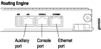
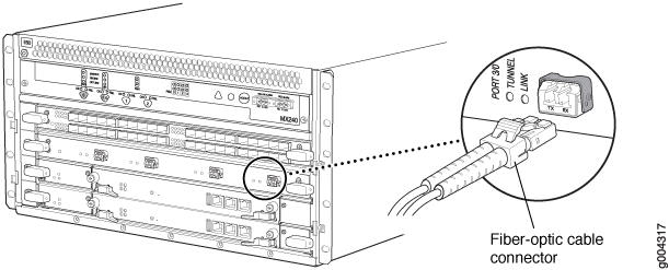
To connect the Routing Engine to a network for out-of-band management, connect an Ethernet cable with RJ-45 connectors to the ETHERNET port on the Routing Engine. To connect to the ETHERNET port on the Routing Engine:
- Turn off the power to the management device.
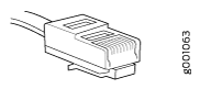
- Plug one end of the Ethernet cable (Figure 2 shows the connector) into the ETHERNET port on the Routing Engine. Figure 1 shows the port.
- Plug the other end of the cable into the network device.
Connecting the MX480 Router to a Management Console or Auxiliary Device
To use a system console to configure and manage the Routing Engine, connect it to the appropriate CONSOLE port on the Routing Engine. To use a laptop, modem, or other auxiliary device, connect it to the AUX port on the Routing Engine. Both ports accept a cable with an RJ-45 connector. To connect a device to the CONSOLE port and another device to the AUX port, you must supply two separate cables.
We no longer include the RJ-45 console cable with the DB-9 adapter as part of the device package. If the console cable and adapter are not included in your device package, or if you need a different type of adapter, you can order the following separately:
-
RJ-45 to DB-9 adapter (JNP-CBL-RJ45-DB9)
-
RJ-45 to USB-A adapter (JNP-CBL-RJ45-USBA)
-
RJ-45 to USB-C adapter (JNP-CBL-RJ45-USBC)
If you want to use RJ-45 to USB-A or RJ-45 to USB-C adapter you must have X64 (64-Bit) Virtual COM port (VCP) driver installed on your PC. See, https://ftdichip.com/drivers/vcp-drivers/ to download the driver.
To connect a management console or auxiliary device:
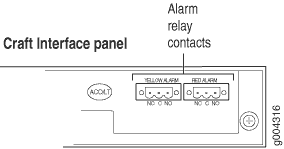
Connecting the MX480 Router to an External Alarm-Reporting Device
To connect the router to external alarm-reporting devices, attach wires to the RED and YELLOW relay contacts on the craft interface. (See Figure 5.) A system condition that triggers the red or yellow alarm LED on the craft interface also activates the corresponding alarm relay contact.
The terminal blocks that plug into the alarm relay contacts are supplied with the router. They accept wire of any gauge between 28-AWG and 14-AWG (0.08 and 2.08 mm2), which is not provided. Use the gauge of wire appropriate for the external device you are connecting.
To connect an external device to an alarm relay contact (see Figure 5):
- Prepare the required length of wire with gauge between 28-AWG and 14-AWG (0.08 and 2.08 mm2).
- While the terminal block is not plugged into the relay contact, use a 2.5-mm flat-blade screwdriver to loosen the small screws on its side. With the small screws on its side facing left, insert wires into the slots in the front of the block based on the wiring for the external device. Tighten the screws to secure the wire.
- Plug the terminal block into the relay contact, and use a 2.5-mm flat-blade screwdriver to tighten the screws on the face of the block.
- Attach the other end of the wires to the external device.
To attach a reporting device for the other kind of alarm, repeat the procedure.
Connecting Line Card Cables to the MX480 Router
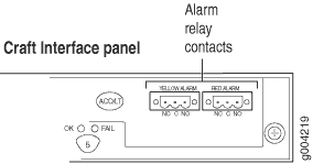
Connecting the Alarm Relay Wires to the MX480 Craft Interface
To connect the alarm relay wires between a router and an alarm-reporting device (see Figure 8):
- Prepare the required length of replacement wire with gauge between 28-AWG and 14-AWG (0.08 and 2.08 mm2).
- Insert the replacement wires into the slots in the front of the block. Use a 2.5-mm flat-blade screwdriver to tighten the screws and secure the wire.
- Attach an ESD grounding strap to your bare wrist, and connect the other end of the strap to an ESD grounding point.
- Plug the terminal block into the relay contact, and use a 2.5-mm flat-blade screwdriver to tighten the screws on the face of the block.
- Attach the other end of the wires to the external device.