Maintaining MX240 Host Subsystem Components
Maintaining the MX240 Host Subsystem
Purpose
For optimum router performance, verify the condition of the host subsystem. The host subsystem comprises an SCB and a Routing Engine installed into a slot in the SCB.
Action
On a regular basis:
Check the LEDs on the craft interface to view information about the status of the Routing Engines.
Check the LEDs on the SCB faceplate.
Check the LEDs on the Routing Engine faceplate.
To check the status of the Routing Engines, issue the
show chassis routing-enginecommand. The output is similar to the following:user@host> show chassis routing-engine Routing Engine status: Slot 0: Current state Master Election priority Master (default) Temperature 45 degrees C / 113 degrees F CPU temperature 43 degrees C / 109 degrees F DRAM 2048 MB Memory utilization 15 percent CPU utilization: User 0 percent Background 0 percent Kernel 8 percent Interrupt 0 percent Idle 92 percent Model RE-S-1300 Serial ID 1000694968 Start time 2007-07-10 12:27:39 PDT Uptime 1 hour, 40 minutes, 37 seconds Load averages: 1 minute 5 minute 15 minute 0.11 0.06 0.01 Routing Engine status: Slot 1: Current state Backup Election priority Backup (default) Temperature 46 degrees C / 114 degrees F CPU temperature 42 degrees C / 107 degrees F DRAM 2048 MB Memory utilization 13 percent CPU utilization: User 0 percent Background 0 percent Kernel 0 percent Interrupt 0 percent Idle 100 percent Model RE-S-1300 Serial ID 1000694976 Start time 2007-06-19 14:17:00 PDT Uptime 20 days, 23 hours, 51 minutes, 4 secondsTo check the status of the SCBs, issue the
show chassis
environment cb
command. The output is similar to the following:user@host> show chassis environment cb CB 0 status: State Online Master Temperature 40 degrees C / 104 degrees F Power 1 1.2 V 1208 mV 1.5 V 1521 mV 1.8 V 1807 mV 2.5 V 2507 mV 3.3 V 3319 mV 5.0 V 5033 mV 12.0 V 12142 mV 1.25 V 1243 mV 3.3 V SM3 3312 mV 5 V RE 5059 mV 12 V RE 11968 mV Power 2 11.3 V bias PEM 11253 mV 4.6 V bias MidPlane 4814 mV 11.3 V bias FPD 11234 mV 11.3 V bias POE 0 11176 mV 11.3 V bias POE 1 11292 mV Bus Revision 42 FPGA Revision 1 CB 1 status: State Online Standby Temperature 40 degrees C / 104 degrees F Power 1 1.2 V 1202 mV 1.5 V 1514 mV 1.8 V 1807 mV 2.5 V 2500 mV 3.3 V 3293 mV 5.0 V 5053 mV 12.0 V 12200 mV 1.25 V 1260 mV 3.3 V SM3 3319 mV 5 V RE 5059 mV 12 V RE 12007 mV Power 2 11.3 V bias PEM 11311 mV 4.6 V bias MidPlane 4827 mV 11.3 V bias FPD 11330 mV 11.3 V bias POE 0 11292 mV 11.3 V bias POE 1 11311 mV Bus Revision 42 FPGA Revision 1
To check the status of a specific SCB,
issue the show chassis environment cb command and include
the slot number of the SCB. The output is similar to the following:
user@host> show chassis environment cb 0
CB 0 status:
  State                      Online
  Temperature Intake         66 degrees C / 150 degrees F
  Temperature Exhaust A      67 degrees C / 152 degrees F
  Temperature Exhaust B      73 degrees C / 163 degrees F
  Power
    1.2 V                     1153 mV
    1.5 V                     1417 mV
    1.8 V                     1704 mV
    2.5 V                     2375 mV
    3.3 V                     3138 mV
    5.0 V                     4763 mV
    1.2 V Rocket IO           1160 mV
    1.5 V Rocket IO           1408 mV
    1.8 V RLDRAM              1717 mV
  I2C Slave Revision         15
For more information about using the CLI, see the Junos OS documenation.
See Also
Replacing an MX240 Routing Engine
Removing an MX240 Routing Engine
Before you remove a Routing Engine, remove the cables that connect to it.
Before you replace a Routing Engine, you must take the host subsystem offline. If there is only one host subsystem, taking the host subsystem offline shuts down the router.
If the Routing Engine to be replaced is currently functioning as the primary Routing engine, switch it to be the backup before removing it.
To remove a Routing Engine from an SCB (see Figure 1):
See Also
Installing an MX240 Routing Engine
To install a Routing Engine into an SCB (Figure 2):
The Routing Engine might require several minutes to boot.
After the Routing Engine boots, verify that it is installed correctly by checking the FAIL, RE0, and RE1 LEDs on the craft interface. If the router is operational and the Routing Engine is functioning properly, the green ONLINE LED lights steadily. If the red FAIL LED lights steadily instead, remove and install the Routing Engine again. If the red FAIL LED still lights steadily, the Routing Engine is not functioning properly. Contact your customer support representative.
To check the status of the Routing Engine, use the CLI command:
user@host> show chassis routing-engine
Routing Engine status:      Slot 0:     Current state                 Master ...
For more information about using the CLI, see the Junos OS documentation.
If enhanced IP network services is configured on the chassis, all routing engines must be rebooted after synchronizing the routing engines. For more information on synchronizing the routing engines, see Synchronizing Routing Engines.
See Also
Replacing an SSD Drive on an RE-S-1800
Each RE-S-1800 Routing Engine supports two solid-state drives (SSD) specified by Juniper Networks. The RE-S-1800 ships with one SSD installed in the slot labeled SATA SSD 1. The spare SSD is Juniper part number SSD-32G-RE-S. Figure 3 shows the arrangement of storage drive slots on a RE-S-1800 Routing Engine.
The following drive has been verified to work in the RE-S-1800 Routing Engine:
SSD-32G-RE-S
To replace a storage drive:
- Disable and deactivate the storage drive—press and hold the Online/Offline button till the LED starts blinking; wait till the RE LEDs are off.
- Remove the storage drive.
- Reinstall a storage drive.
- Carefully align the sides of the drive with the guides in the slot.
- Slide the drive into the slot until you feel resistance, carefully ensuring that it is correctly aligned.
- Close the access door and tighten the thumbscrew to secure the door.
See Also
Replacing an SSD Drive on an RE-S-X6-64G
- Replace the SSD Drives on an RE-S-X6-64G
- Copy the Junos OS to the Newly Replaced SSD Using a USB disk (Minimum 16-GB)
Replace the SSD Drives on an RE-S-X6-64G
Each RE-S-X6-64G Routing Engine supports two solid-state drives (SSD) specified by Juniper Networks. The RE-S-X6-64G ships with two SSDs installed in the slot labeled SSD1 and SSD2. Figure 4 shows the arrangement of storage drive slots on a RE-S-X6-64G Routing Engine.
Make sure that the Routing Engine does not contain a mix of 50 GB and 200 GB SSDs. The SSDs on the Routing Engine must be from the same vendor. Both SSDs in the routing engine must be of the same type and must contain the same disk capacity. You must upgrade the two 50 GB SSDs to two 200 GB SSDs at the same time as mixed-mode operation is not supported.
Replacing an SSD drive in a RE-S-X6-64G Routing Engine consists of the following two stages:
-
Replacing the SSD drives in the Routing Engine
-
Copy the Junos OS to the newly replaced SSD
1 — Extractor clips | 6 — ONLINE/OFFLINE Button |
2 — Auxiliary port (AUX) | 7 — SSD LEDs—DISK1 and DISK2 |
3 — Console port (Con) | 8 — Ports—USB1 and USB2 |
4 — Management port (MGMT) | 9 — RESET Button |
5 — LEDs—ONLINE, OK/FAIL, and MASTER | 10 — SSD card slot cover |
Replacing Both the SSDs in the Routing Engine:
Make sure that the Routing Engine does not contain a mix of 50 GB and 200 GB SSDs. The SSDs on the Routing Engine must be from the same vendor. Both SSDs in the routing engine must be of the same type and must contain the same disk capacity. You must upgrade the two 50 GB SSDs to two 200 GB SSDs at the same time as mixed-mode operation is not supported.
Ensure that you keep a bootable USB disk ready if installing vmhost and Junos OS using an USB disk. To prepare a bootable USB disk, see Creating an Emergency Boot Device for Routing Engines with VM Host Support.
-
From the backup Routing Engine (RE1), remove the SSDs from slot SSD1 and slot
SSD2.
Figure 5: Removing an SSD in the Routing Engine RE-S-X6-64G
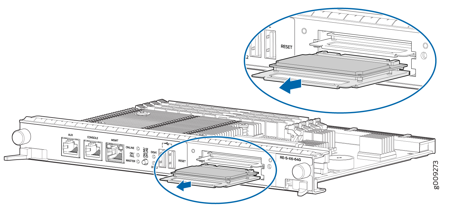
-
Insert the new SSDs in slot SSD1 and slot SSD2. See Figure 6.
Figure 6: Installing an SSD in the Routing Engine RE-S-X6-64G
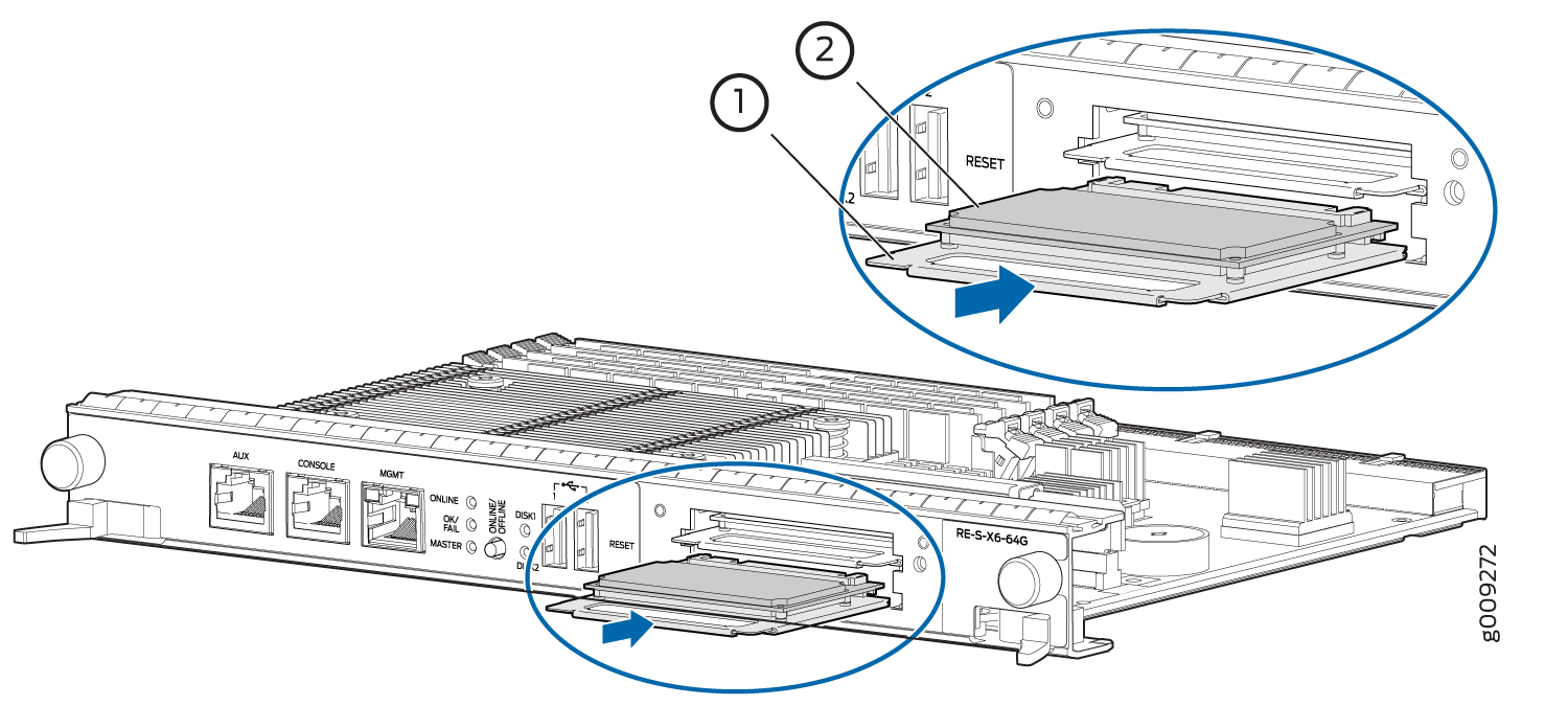 1—
1—Carrier
2—SSD card
- Carefully align the sides of the drive with the guides in the slot.
- Slide the drive into the slot until you feel resistance, carefully ensuring that it is correctly aligned.
- Close the access door and tighten the thumbscrew to secure the door.
Replacing Disk2 (SSD2) Only in the Routing Engine:
Make sure that the Routing Engine does not contain a mix of 50 GB and 200 GB SSDs. The SSDs on the Routing Engine must be from the same vendor. Both SSDs in the routing engine must be of the same type and must contain the same disk capacity. You must upgrade the two 50 GB SSDs to two 200 GB SSDs at the same time as mixed-mode operation is not supported.
Make sure the router is booted up and running from an image from disk1 (execute the
request vmhost reboot disk1command to boot from disk1).Remove disk2 and replace with a new disk (refer step 3 to step 4).
Reboot the Routing Engine by executing the
request vmhost rebootcommand.The router boots from disk1 when disk2 is replaced. To be able to boot from disk2, execute the
request vmhost snapshot partitioncommand.
Replacing Disk1 (SSD1) Only:
Make sure that the Routing Engine does not contain a mix of 50 GB and 200 GB SSDs. The SSDs on the Routing Engine must be from the same vendor. Both SSDs in the routing engine must be of the same type and must contain the same disk capacity. You must upgrade the two 50 GB SSDs to two 200 GB SSDs at the same time as mixed-mode operation is not supported.
Make sure the router is booted up and running from an image from disk2 (execute the
request vmhost reboot disk2command to boot from disk2).Remove disk1 and replace with a new disk (refer step 3 to step 4).
Reboot the Routing Engine by executing the
request vmhost rebootcommand.The router boots from disk2 when disk1 is replaced. To be able to boot from disk1, execute the
request vmhost snapshot recovery partitioncommand.Boot from disk1 by executing the
request vmhost reboot disk1command.
See Also
Copy the Junos OS to the Newly Replaced SSD Using a USB disk (Minimum 16-GB)
In addition to installing Junos OS from the USB device, you can also install the VM Host and Junos OS using a Preboot Execution Environment (PXE) boot server. For more information, see Installing, Upgrading, Backing Up, and Recovery of VM Host.
Replacing Connections to MX240 Routing Engine Interface Ports
- Replacing the Management Ethernet Cable on an MX240 Router
- Replacing the Console or Auxiliary Cable on an MX240 Router
Replacing the Management Ethernet Cable on an MX240 Router
To replace the cable connected to the ETHERNET port:
- Attach an ESD grounding strap to your bare wrist, and connect the other end of the strap to an ESD grounding point.
- Press the tab on the connector, and pull the connector straight out of the port. Figure 7 shows the connector.
- Disconnect the cable from the network device.
- Plug one end of the replacement cable into the ETHERNET port. Figure 8 shows the port.
- Plug the other end of the cable into the network device.
See Also
Replacing the Console or Auxiliary Cable on an MX240 Router
To use a system console to configure and manage the Routing Engine, connect it to the CONSOLE port on the Routing Engine. To use a laptop, modem, or other auxiliary device, connect it to the AUX port on the Routing Engine. Both ports accept a cable with an RJ-45 connector. If you want to connect a device to both ports, you must supply two separate cables.
We no longer include the RJ-45 console cable with the DB-9 adapter as part of the device package. If the console cable and adapter are not included in your device package, or if you need a different type of adapter, you can order the following separately:
-
RJ-45 to DB-9 adapter (JNP-CBL-RJ45-DB9)
-
RJ-45 to USB-A adapter (JNP-CBL-RJ45-USBA)
-
RJ-45 to USB-C adapter (JNP-CBL-RJ45-USBC)
If you want to use RJ-45 to USB-A or RJ-45 to USB-C adapter you must have X64 (64-Bit) Virtual COM port (VCP) driver installed on your PC. See, https://ftdichip.com/drivers/vcp-drivers/ to download the driver.
To replace a cable connected to a management console or auxiliary device:
- Attach an ESD grounding strap to your bare wrist, and connect the other end of the strap to an ESD grounding point.
- Press the tab on the connector, and pull the connector straight out of the port.
- Disconnect the cable from the console or auxiliary device.
- Plug the RJ-45 end of the replacement serial cable into the CONSOLE or AUX port. Figure 9 shows the external device ports on the Routing Engine.
- Plug the female DB-9 end into the console or auxiliary device's serial port.
See Also
Upgrading to the RE-S-X6-64G Routing Engine in a Redundant Host Subsystem
A redundant host subsystem consists of a primary Routing Engine (RE0) and a backup Routing Engine (RE1). To upgrade the host subsystem to use the RE-S-X6-64G Routing Engine, you must first uninstall the backup Routing Engine and install the RE-S-X6-64G Routing Engine, which then becomes the backup Routing Engine. You then switch over this backup Routing Engine to make it the primary Routing Engine. Replace the other Routing Engine and configure it as the backup Routing Engine.
Ensure that the Switch Control Board in the chassis is SCBE2 or SCBE3 because the RE-S-X6-64G Routing Engine is not compatible with the Switch Control Boards SCB or SCBE. To upgrade the Switch Control Board to SCBE2, see Upgrading an MX240 to Use the SCBE2-MX, Upgrading an MX480 to Use the SCBE2-MX or Upgrading an MX960 to Use the SCBE2-MX, depending on the chassis on which the Routing Engine is being upgraded. To upgrade the Switch Control Board to SCBE3 Upgrading an MX240, MX480, or MX960 Router to Use the SCBE3-MX.
Save the router configuration before proceeding with the Routing Engine upgrade.
Nonstop active routing (NSR) and graceful Routing Engine
switchover (GRES) are not supported during the upgrade and they must
be temporarily disabled. Disable NSR by removing the nonstop-routing statement from the [edit routing-options] hierarchy level
and by removing the graceful-switchover statement from
the [edit chassis redundancy] hierarchy level .
- Removing the Routing Engine
- Installing the Routing Engine RE-S-X6-64G
- Verifying and Configuring the Upgraded Routing Engine as the Primary
- Verifying and Configuring the Upgraded Routing Engine as the Backup
Removing the Routing Engine
- On the external management device connected to the Routing
Engine, shut down the host subsystem by using the
request system power-offcommand. - Wait until a message appears on the console confirming that the operating system has halted.
- Remove the cables connected to the Routing Engine.
- Place an electrostatic bag or antistatic mat on a flat, stable surface. Attach an electrostatic discharge (ESD) grounding strap to your bare wrist and connect the strap to one of the ESD points on the chassis.
- Verify that the Routing Engine LEDs are off. Loosen the captive screws on the top and bottom of the Routing Engine.
- Grasp the Routing Engine by the ejector handles, and slide it about halfway out of the chassis.
- Place one hand underneath the Routing Engine to support it, and slide it completely out of the chassis. Place the Routing Engine on the antistatic mat.
To maintain proper airflow through the chassis, do not leave an SCB installed in the chassis without a Routing Engine for extended periods of time. If a Routing Engine is removed, a replacement Routing Engine should be installed as soon as possible.
Installing the Routing Engine RE-S-X6-64G
To install the Routing Engine RE-S-X6-64G:
The Routing Engine might require several minutes to boot. After the Routing Engine boots, verify that it is installed correctly by checking the FAIL, RE0, and RE1 LEDs on the craft interface. If the router is operational and the Routing Engine is functioning properly, the green ONLINE LED on the Routing Engine lights steadily. If the red FAIL LED on the Routing Engine lights steadily instead, remove and install the Routing Engine again. If the red FAIL LED still lights steadily, the Routing Engine is not functioning properly. Contact your customer support representative.
Verifying and Configuring the Upgraded Routing Engine as the Primary
After replacing the backup Routing Engine with the RE-S-X6-64G Routing Engine, perform the following steps:
-
Verify that the SCBE2 or SCBE3 and RE-S-X6-64G Routing Engine are online
by issuing the
show chassis hardwarecommand. - After you install the RE-S-X6-64G Routing Engine into the SCBE2 or SCBE3, the Routing Engine gets automatically powered on and comes up in amnesiac mode as it is loaded with factory defaults. After the Routing Engine comes up in amnesiac mode, load the base configuration and commit.
- Configure the backup Routing Engine by using the
commit synchronizecommand to copy the configuration to the backup Routing Engine. - Use the
request chassis routing-engine master switchcommand to make the Routing Engine RE-S-X6-64G (RE1) the primary Routing Engine. All FPCs reboot after this step.
Verifying and Configuring the Upgraded Routing Engine as the Backup
- Use the
request chassis routing-engine master switchcommand to make newly installed RE-S-X6-64G (RE0) the backup Routing Engine. - Use the
commit synchronizecommand to copy the active configuration from the primary Routing Engine to the backup Routing Engine.
Upgrading to the RE-S-X6-64G Routing Engine in a Nonredundant Host Subsystem
In a nonredundant host subsystem, only one Routing Engine and one Switch Control Board are present in the chassis. When you are upgrading the Routing Engine, taking the host subsystem offline shuts down the router. To upgrade the host subsystem with the RE-S-X6-64G Routing Engine, you must uninstall the existing Routing Engine and install the RE-S-X6-64G Routing Engine. Ensure that the Switch Control Board in the chassis is SCBE2 because the RE-S-X6-64G Routing Engine is not compatible with the Switch Control Boards SCB or SCBE. To upgrade the Switch Control Board to SCBE2, see Upgrading an MX240 to Use the SCBE2-MX, Upgrading an MX480 to Use the SCBE2-MXor Upgrading an MX960 to Use the SCBE2-MX, depending on the chassis on which the Routing Engine is being upgraded. .
Save the router configuration before proceeding with the Routing Engine upgrade.
Removing the Routing Engine
To remove the Routing Engine from the chassis:
- On the external management device connected to the Routing
Engine, shut down the host subsystem by using the
request system
power-off
command. - Wait until a message appears on the console confirming that the operating system has halted.
- Remove the cables connected to the Routing Engine.
- Place an electrostatic bag or antistatic mat on a flat, stable surface. Attach an ESD grounding strap to your bare wrist and connect the strap to one of the ESD points on the chassis.
- Verify that the Routing Engine LEDs are off. Loosen the captive screws on the top and bottom of the Routing Engine.
- Grasp the Routing Engine by the ejector handles, and slide it about halfway out of the chassis.
- Place one hand underneath the Routing Engine to support it, and slide it completely out of the chassis. Place the Routing Engine on the antistatic mat.
To maintain proper airflow through the chassis, do not leave an SCB installed in the chassis without a Routing Engine for extended periods of time. If a Routing Engine is removed, a replacement Routing Engine should be installed as soon as possible.
Installing the Routing Engine RE-S-X6-64G
To install the new Routing Engine (RE-S-X6-64G):
The Routing Engine might require several minutes to boot. After the Routing Engine boots, verify that it is installed correctly by checking the FAIL, RE0, and RE1 LEDs on the craft interface. If the router is operational and the Routing Engine is functioning properly, the green ONLINE LED on the Routing Engine lights steadily. If the red FAIL LED lights steadily instead, remove the Routing Engine and reinstall it. If the red FAIL LED on the Routing Engine still lights steadily, the Routing Engine is not functioning properly. Contact your customer support representative.
Replacing the MX240 Craft Interface
- Disconnecting the Alarm Relay Wires from the MX240 Craft Interface
- Removing the MX240 Craft Interface
- Installing the MX240 Craft Interface
- Connecting the Alarm Relay Wires to the MX240 Craft Interface
Disconnecting the Alarm Relay Wires from the MX240 Craft Interface
To disconnect the alarm relay wires from the router and an alarm-reporting device (see Figure 16):
- Disconnect the existing wire at the external device.
- Attach an ESD grounding strap to your bare wrist, and connect the other end of the strap to an ESD grounding point.
- Using a 2.5-mm flat-blade screwdriver, loosen the small screws on the face of the terminal block and remove the block from the relay contact.
- Using the 2.5-mm flat-blade screwdriver, loosen the small screws on the side of the terminal block. Remove existing wires from the slots in the front of the block.
See Also
Removing the MX240 Craft Interface
To remove the craft interface (see Figure 17):
- Attach an ESD grounding strap to your bare wrist, and connect the other end of the strap to an ESD grounding point.
- Detach any external devices connected to the craft interface.
- Loosen the captive screws at the left and right corners of the craft interface faceplate.
- Grasp the craft interface faceplate and carefully tilt it toward you until it is horizontal.
- Disconnect the ribbon cable from the back of the faceplate by gently pressing on both sides of the latch with your thumb and forefinger. Remove the craft interface from the chassis.
See Also
Installing the MX240 Craft Interface
To install the craft interface (see Figure 18):
- Attach an ESD grounding strap to your bare wrist, and connect the other end of the strap to an ESD grounding point.
- Grasp the craft interface with one hand, and hold the bottom edge of the craft interface with the other hand to support its weight.
- Orient the ribbon cable so that it plugs into the connector socket. The connector is keyed and can be inserted only one way.
- Align the bottom of the craft interface with the sheet metal above the card cage and press it into place.
- Tighten the screws on the left and right corners of the craft interface faceplate.
- Reattach any external devices connected to the craft interface.
See Also
Connecting the Alarm Relay Wires to the MX240 Craft Interface
To connect the alarm relay wires between a router and an alarm-reporting device (see Figure 19):
- Prepare the required length of replacement wire with gauge between 28-AWG and 14-AWG (0.08 and 2.08 mm2).
- Insert the replacement wires into the slots in the front of the block. Use a 2.5-mm flat-blade screwdriver to tighten the screws and secure the wire.
- Attach an ESD grounding strap to your bare wrist, and connect the other end of the strap to an ESD grounding point.
- Plug the terminal block into the relay contact, and use a 2.5-mm flat-blade screwdriver to tighten the screws on the face of the block.
- Attach the other end of the wires to the external device.