ACX1000 and ACX1100 System Overview
ACX1000 and ACX1100 Universal Metro Router Overview
The ACX1000 and ACX1100 Universal Metro Routers are principally designed to provide superior management for rapid provisioning to the access network. The ACX Series routers support rich Gigabit Ethernet and 10-Gigabit Ethernet capabilities for uplink, along with support for legacy interfaces and Gigabit Ethernet interfaces in a compact form factor that is environmentally hardened and passively cooled. Seamless, end-to-end MPLS can be used to address legacy and emerging requirements to provide the foundation for a converged network that utilizes the same mobile backhaul infrastructure for business or residential services.
The routers are single-board routers with a built-in Routing Engine and one Packet Forwarding Engine. The Packet Forwarding Engine has one “pseudo” Flexible PIC Concentrator (FPC 0). Because there is no switching fabric, the single Packet Forwarding Engine takes care of packet forwarding.
Routing Engine—Provides Layer 3 routing services and network management.
Packet Forwarding Engine—Performs Layer 2 and Layer 3 packet switching, route lookups, and packet forwarding.
The ACX Series router is powered by Junos OS, supporting extensive L2 and L3 features, IP and MPLS with traffic engineering, rich network management, fault management, service monitoring and Operation, Administration, and Maintenance (OAM) capabilities, and an open software development kit (SDK) system that allows providers to customize and integrate operations with their own management systems. For a list of related Junos OS documentation, see https://www.juniper.net/documentation/software/junos/.
As part of the mobile backhaul, the ACX Series router at the cell site and the MX Series router at the aggregation layer provide comprehensive end-to-end Ethernet, MPLS, and OAM features with the one Junos OS running on both platforms.
The compact routers are one rack unit (U; that is, 1.75 in., or 4.45 cm) tall. Several routers can be stacked in a single floor-to-ceiling rack for increased port density per unit of floor space.
The chassis is a rigid sheet metal structure that houses all the other router components. The chassis measures 1.75 in. (4.45 cm) high, 9.4 in. (24 cm) deep, and 17.5 in. (44.5 cm) wide. The outer edges of the mounting brackets extend the width to 19 in. (48 cm) (from the front-mounting brackets to the rear of the chassis). The chassis installs in standard 300-mm deep (or larger) enclosed cabinets, 19-in. equipment racks, or telco open-frame racks.
Benefits of the ACX1000 and ACX1100 Routers
Space efficiency—Conforming to the ETSI 300 specifications, the ACX1000 routers are easy to deploy in environments where rack space and cooling are limited.
Improved operational efficiency with zero-touch deployment (ZTD)—The ACX Series routers support a zero-touch deployment (ZTD) model that significantly reduces the time for any new equipment installation and provisioning, resulting in improved operational efficiency.
Installation flexibility with an environmentally hardened design—Most ACX Series routers are temperature hardened and support passive cooling for outdoor deployments in extreme weather conditions.
ACX1000 Router Description
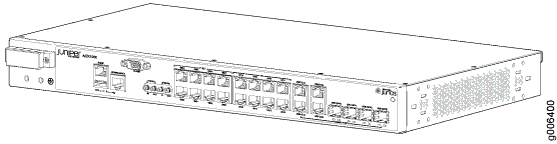
The ACX1000 routers contain eight T1/E1 ports and twelve Gigabit Ethernet ports, eight of which are RJ-45 ports. The ports labeled COMBO PORTS provide an additional four RJ-45 ports or four Gigabit Ethernet SFP ports. You can use only one set of combination ports at a time.
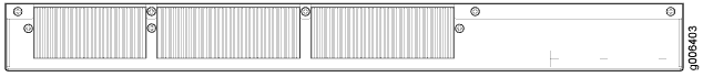
Figure 1 and Figure 2 show the front and rear views of the ACX1000 router.
ACX1100 Router Description
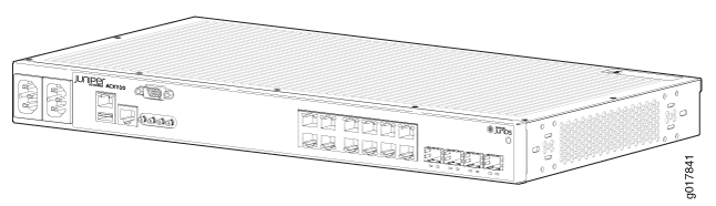
The ACX1100 routers contain twelve Gigabit Ethernet ports, eight of which are RJ-45 ports. The ports labeled COMBO PORTS provide an additional four RJ-45 ports or four Gigabit Ethernet SFP ports. You can only use one set of combination ports at a time.
Figure 3 and Figure 4 show the front and rear views of the ACX1100 router.
See Also
ACX1000 and ACX1100 Routers Hardware and CLI Terminology Mapping
- ACX1000 and ACX1100 Routers Hardware and CLI Terminology Mapping
- ACX1100 Routers Hardware and CLI Terminology Mapping
ACX1000 and ACX1100 Routers Hardware and CLI Terminology Mapping
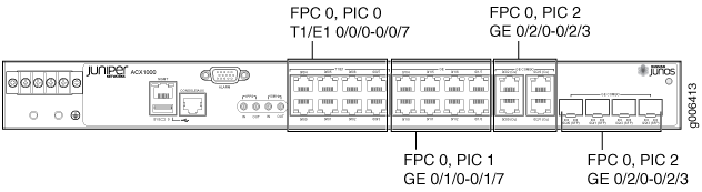
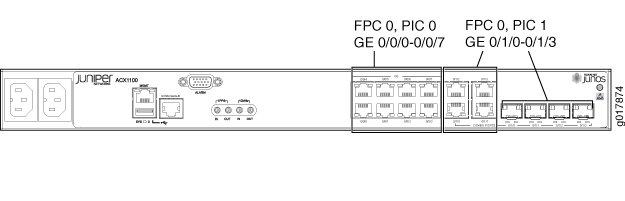
Table 1 describes the hardware terms used in ACX1000 router documentation and the corresponding terms used in the Junos OS command line interface (CLI). Figure 5 shows the port locations of the interfaces.
Hardware Item (as displayed in the CLI) |
Description (as displayed in the CLI) |
Value (as displayed in the CLI) |
Item in Documentation |
Additional Information |
|---|---|---|---|---|
Chassis |
ACX1000 |
– |
Router chassis |
Chassis Physical Specifications for ACX1000 and ACX1100 Routers |
FPC (n) |
Abbreviated name of the Flexible PIC Concentrator (FPC) |
Value of n is always 0. |
The router does not have actual FPCs. In this case, FPC refers to the router itself. |
Interface Naming Conventions Used in the Junos OS Operational Commands |
PIC (n) |
Abbreviated name of the Physical Interface Card (PIC) |
n is a value in the range of 0–2. |
The router does not have actual PIC devices; see entries for PIC 0 through PIC 2 for the equivalent item on the router. |
Interface Naming Conventions Used in the Junos OS Operational Commands |
8x T1/E1 (RJ-48) |
PIC 0 |
Built-in network ports on the front panel of the router |
||
8x 1GE (RJ-45) |
PIC 1 |
Built-in uplink ports on the front panel of the router |
||
One of the following:
|
PIC 2 |
Built-in uplink ports on the front panel of the router |
||
Xcvr (n) |
Abbreviated name of the transceiver |
n is a value equivalent to the number of the port in which the transceiver is installed. |
Optical transceivers |
|
Power supply (n) |
Built-in power supply |
Value of n is always 0. |
DC power supply |
|
Fan |
Fan |
– |
Fan |
ACX1100 Routers Hardware and CLI Terminology Mapping
Table 2 describes the hardware terms used in ACX1100 router documentation and the corresponding terms used in the Junos OS command line interface (CLI). Figure 6 shows the port locations of the interfaces.
Hardware Item (as displayed in the CLI) |
Description (as displayed in the CLI) |
Value (as displayed in the CLI) |
Item in Documentation |
Additional Information |
|---|---|---|---|---|
Chassis |
ACX1100 |
– |
Router chassis |
Chassis Physical Specifications for ACX1000 and ACX1100 Routers |
FPC (n) |
Abbreviated name of the Flexible PIC Concentrator (FPC) |
Value of n is always 0. |
The router does not have actual FPCs. In this case, FPC refers to the router itself. |
Interface Naming Conventions Used in the Junos OS Operational Commands |
PIC (n) |
Abbreviated name of the Physical Interface Card (PIC) |
n is a value in the range of 0–1. |
The router does not have actual PIC devices; see entries for PIC 0 through PIC 2 for the equivalent item on the router. |
Interface Naming Conventions Used in the Junos OS Operational Commands |
8x 1GE (RJ-45) |
PIC 0 |
Built-in uplink ports on the front panel of the router |
||
One of the following:
|
PIC 1 |
Built-in uplink ports on the front panel of the router |
||
Xcvr (n) |
Abbreviated name of the transceiver |
n is a value equivalent to the number of the port in which the transceiver is installed. |
Optical transceivers |
|
Power supply (n) |
Built-in power supply |
Value of n is always 0. |
AC or DC power supply |
|
Fan |
Fan Note:
ACX1100 routers are fanless models. |
– |
Fan |
Packet Flow on ACX Series Routers
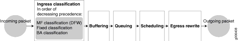
The class-of-service (CoS) architecture for ACX Series routers is in concept similar to that for MX Series routers. The general architecture for ACX Series routers is shown in Figure 7.
Based on the model, ACX Series routers contain a built-in Routing Engine and Packet Forwarding Engine and can contain both T1/E1 and Gigabit Ethernet Ports.
The Packet Forwarding Engine has one or two “pseudo” Flexible PIC Concentrators. Because there is no switching fabric, the single Packet Forwarding Engine takes care of both ingress and egress packet forwarding.
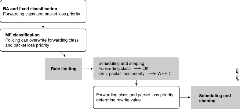
Fixed classification places all packets in the same forwarding class, or the usual multifield (MF) or behavior aggregate (BA) classifications can be used to treat packets differently. BA classification with firewall filters can be used for classification based on IP precedence, DSCP, IEEE, or other bits in the frame or packet header.
However, the ACX Series routers can also employ multiple BA classifiers on the same physical interface. The physical interfaces do not have to employ the same type of BA classifier. For example, a single physical interface can use classifiers based on IP precedence as well as IEEE 802.1p. If the CoS bits of interest are on the inner VLAN tag of a dual-tagged VLAN interface, the classifier can examine either the inner or outer bits. (By default, the classification is done based on the outer VLAN tag.)
Eight queues per egress port support scheduling using the weighted deficit round- robin (WDRR) mechanism, a form of round-robin queue servicing. The supported priority levels are strict-high and default (low). The ACX Series router architecture supports both weighted random early detect (WRED) and weighted tail drop (WTD).
All CoS features are supported at line rate.
The packet pipeline through an ACX Series router is shown in Figure 8. Note that the rate limiting is done with an integrated architecture along with all other CoS functions. Scheduling and shaping are supported on the output side.
See Also
Protocols and Applications Supported by ACX Series Routers
Table 3 contains the first Junos OS Release support for protocols and applications on ACX Series routers. A dash indicates that the protocol or application is not supported.
The [
edit logical-systems logical-system-name] hierarchy level is not supported on ACX Series routers.The ACX Series routers does not support per-family maximum transmission unit (MTU) configuration. The MTU applied to family
inetgets applied to other families as well, even though it can be configured though CLI and visible inshow interface extensiveoutput. The only way to use higher MTU for a family is to manipulate the MTU, apply at interface orfamily inetlevels, and let it calculate for each family automatically. MTU values are not limited to 1500 but can range between 256 to 9216.For more information, see the Knowledge Base (KB) article KB28179 at: https://kb.juniper.net/InfoCenter/index?page=content&id=KB28179.
Protocol or Application |
ACX1000 |
ACX1100 |
ACX2000 |
ACX2100 |
ACX2200 |
ACX4000 |
ACX5048 |
ACX5096 |
ACX500 |
ACX5448 |
|---|---|---|---|---|---|---|---|---|---|---|
| Interface and Encapsulation Types | ||||||||||
Ethernet interfaces—1G, 10G |
12.2 |
12.2R2 |
12.2 |
12.2R2 |
12.3X54–D15 |
12.3x51-D10 |
15.1X54–D20 |
15.1X54–D20 |
12.3X54–D20 (Indoor) 12.3X54–D25 (Outdoor) |
18.2R1 |
Ethernet interfaces—40G |
– |
– |
– |
– |
– |
– |
15.1X54–D20 |
15.1X54–D20 |
– |
18.2R1 |
ATM interfaces (IMA only) |
12.2 |
– |
12.2 |
12.2R2 |
– |
– |
– |
– |
– |
– |
E1 interfaces |
12.2 |
– |
12.2 |
12.2R2 |
– |
– |
– |
– |
– |
– |
T1 interfaces |
12.2 |
– |
12.2 |
12.2R2 |
– |
– |
– |
– |
– |
– |
Circuit emulation interfaces (SAToP, CESoP) |
12.2 |
– |
12.2 |
12.2R2 |
- |
12.3x51-D10 |
– |
– |
– |
– |
SONET/SDH interfaces |
– |
– |
– |
– |
– |
12.3x51-D10 (requires a MIC) |
– |
– |
– |
– |
| Layer 3 | ||||||||||
Static routes |
12.2 |
12.2R2 |
12.2 |
12.2R2 |
12.3X54–D15 |
12.3x51-D10 |
15.1X54–D20 |
15.1X54–D20 |
12.3X54–D20 (Indoor) 12.3X54–D25 (Outdoor) |
18.2R1 |
OSPF |
12.2 |
12.2R2 |
12.2 |
12.2R2 |
12.3X54–D15 |
12.3x51-D10 |
15.1X54–D20 |
15.1X54–D20 |
12.3X54–D20 (Indoor) 12.3X54–D25 (Outdoor) |
18.2R1 |
IS-IS |
12.2 |
12.2R2 |
12.2 |
12.2R2 |
12.3X54–D15 |
12.3x51-D10 |
15.1X54–D20 |
15.1X54–D20 |
12.3X54–D20 (Indoor) 12.3X54–D25 (Outdoor) |
18.2R1 |
BGP |
12.2 |
12.2R2 |
12.2 |
12.2R2 |
12.3X54–D15 |
12.3x51-D10 |
15.1X54–D20 |
15.1X54–D20 |
12.3X54–D20 (Indoor) 12.3X54–D25 (Outdoor) |
18.2R1 |
Internet Control Message Protocol (ICMP) |
12.2 |
12.2R2 |
12.2 |
12.2R2 |
12.3X54–D15 |
12.3x51-D10 |
15.1X54–D20 |
15.1X54–D20 |
12.3X54–D20 (Indoor) 12.3X54–D25 (Outdoor) |
18.2R1 |
Address Resolution Protocol (ARP) |
12.2 |
12.2R2 |
12.2 |
12.2R2 |
12.3X54–D15 |
12.3x51-D10 |
15.1X54–D20 |
15.1X54–D20 |
12.3X54–D20 (Indoor) 12.3X54–D25 (Outdoor) |
18.2R1 |
Bidirectional Forwarding Detection (BFD) protocol |
12.2 |
12.2R2 |
12.2 |
12.2R2 |
12.3X54–D15 |
12.3x51-D10 |
15.1X54–D20 |
15.1X54–D20 |
12.3X54–D20 (Indoor) 12.3X54–D25 (Outdoor) |
18.2R1 |
Dynamic Host Configuration Protocol (DHCP) |
12.2 |
12.2R2 |
12.2 |
12.2R2 |
12.3X54–D15 |
12.3x51-D10 |
15.1X54–D20 |
15.1X54–D20 |
12.3X54–D20 (Indoor) 12.3X54–D25 (Outdoor) |
18.2R1 |
IP fast reroute (FRR) (OSPF, IS-IS) |
12.2 |
12.2R2 |
12.2 |
12.2R2 |
12.3X54–D15 |
12.3x51-D10 |
15.1X54–D20 |
15.1X54–D20 |
12.3X54–D20 (Indoor) 12.3X54–D25 (Outdoor) |
18.2R1 |
Maximum transmission unit (MTU) range (256 to 9192) |
12.2 |
12.2R2 |
12.2 |
12.2R2 |
12.3X54–D15 |
12.3x51-D10 |
15.1X54–D20 |
15.1X54–D20 |
12.3X54–D20 (Indoor) 12.3X54–D25 (Outdoor) |
18.2R1 |
Layer 3 VPNs |
12.3R1 |
12.3R1 |
12.3R1 |
12.3R1 |
12.3X54–D15 |
12.3x51-D10 |
15.1X54–D20 |
15.1X54–D20 |
12.3X54–D20 (Indoor) 12.3X54–D25 (Outdoor) |
18.2R1 |
RSVP |
12.2 |
12.2R2 |
12.2 |
12.2R2 |
12.3X54–D15 |
12.3x51-D10 |
15.1X54–D20 |
15.1X54–D20 |
12.3X54–D20 (Indoor) 12.3X54–D25 (Outdoor) |
18.2R1 |
LDP (targeted and direct) |
12.2 |
12.2R2 |
12.2 |
12.2R2 |
12.3X54–D15 |
12.3x51-D10 |
15.1X54–D20 |
15.1X54–D20 |
12.3X54–D20 (Indoor) 12.3X54–D25 (Outdoor) |
18.2R1 |
| MPLS, VPLS, VPNs | ||||||||||
Static label-switched path (LSP) |
12.2 |
12.2R2 |
12.2 |
12.2R2 |
12.3X54–D15 |
12.3x51-D10 |
15.1X54–D20 |
15.1X54–D20 |
12.3X54–D20 (Indoor) 12.3X54–D25 (Outdoor) |
18.2R1 |
FRR |
12.2 |
12.2R2 |
12.2 |
12.2R2 |
12.3X54–D15 |
12.3x51-D10 |
15.1X54–D20 |
15.1X54–D20 |
12.3X54–D20 (Indoor) 12.3X54–D25 (Outdoor) |
18.2R1 |
Traffic engineering |
12.2 |
12.2R2 |
12.2 |
12.2R2 |
12.3X54–D15 |
12.3x51-D10 |
15.1X54–D20 |
15.1X54–D20 |
12.3X54–D20 (Indoor) 12.3X54–D25 (Outdoor) |
18.2R1 |
E-LINE |
12.2 |
12.2R2 |
12.2 |
12.2R2 |
12.3X54–D15 |
12.3x51-D10 |
15.1X54–D20 |
15.1X54–D20 |
12.3X54–D20 (Indoor) 12.3X54–D25 (Outdoor) |
18.2R1 |
Pseudowire Emulation Edge to Edge (PWE3 [signaled]) |
12.2 |
– |
12.2 |
12.2R2 |
12.3X54–D15 |
12.3x51-D10 |
15.1X54–D20 |
15.1X54–D20 |
– |
18.2R1 |
Static Ethernet PWs |
12.2 |
12.2R2 |
12.2 |
12.2R2 |
12.3X54–D15 |
12.3x51-D10 |
15.1X54–D20 |
15.1X54–D20 |
12.3X54–D20 (Indoor) 12.3X54–D25 (Outdoor) |
18.2R1 |
Layer 2 circuits |
12.2 |
12.2R2 |
12.2 |
12.2R2 |
12.3X54–D15 |
12.3x51-D10 |
15.1X54–D20 |
15.1X54–D20 |
12.3X54–D20 (Indoor) 12.3X54–D25 (Outdoor) |
18.2R1 |
IEE802.1ag CC monitoring on active and standby pseudowires |
12.2 |
12.2R2 |
12.2 |
12.2R2 |
12.3X54–D15 |
12.3x51-D10 |
15.1X54–D20 |
15.1X54–D20 |
12.3X54–D20 (Indoor) 12.3X54–D25 (Outdoor) |
18.2R1 |
VPLS |
– |
– |
– |
– |
– |
– |
15.1X54–D20 |
15.1X54–D20 |
– |
18.2R1 |
| Ethernet Layer 2 | ||||||||||
Ethernet in the first mile (EFM 802.3ah) |
12.2 |
12.2R2 |
12.2 |
12.2R2 |
12.3X54–D15 |
12.3x51-D10 |
15.1X54–D20 |
15.1X54–D20 |
12.3X54–D20 (Indoor) 12.3X54–D25 (Outdoor) |
18.2R1 |
802.1ag connectivity fault management (CFM) |
12.2 |
12.2R2 |
12.2 |
12.2R2 |
12.3X54–D15 |
12.3x51-D10 |
15.1X54–D20 |
15.1X54–D20 |
12.3X54–D20 (Indoor) 12.3X54–D25 (Outdoor) |
18.2R1 |
IEE802.1ag interface-status type, length, and value (TLV) |
12.2 |
12.2R2 |
12.2 |
12.2R2 |
12.3X54–D15 |
12.3x51-D10 |
15.1X54–D20 |
15.1X54–D20 |
12.3X54–D20 (Indoor) 12.3X54–D25 (Outdoor) |
18.2R1 |
| QoS | ||||||||||
12.2 |
12.2R2 |
12.2 |
12.2R2 |
12.3X54–D15 |
12.3x51-D10 |
15.1X54–D20 |
15.1X54–D20 |
12.3X54–D20 (Indoor) 12.3X54–D25 (Outdoor) |
18.2R1 |
|
12.2 |
12.2R2 |
12.2 |
12.2R2 |
12.3X54–D15 |
12.3x51-D10 |
15.1X54–D20 |
15.1X54–D20 |
12.3X54–D20 (Indoor) 12.3X54–D25 (Outdoor) |
18.2R1 |
|
Firewall filters—family ccc/any |
12.2 |
12.2R2 |
12.2 |
12.2R2 |
12.3X54–D15 |
12.3x51-D10 |
15.1X54–D20 |
15.1X54–D20 |
12.3X54–D20 (Indoor) 12.3X54–D25 (Outdoor) |
18.2R1 |
Firewall - Port Mirroring |
12.2R1 |
12.2R2 |
12.2R1 |
12.2R2 |
12.3X54–D15 |
12.3x51-D10 |
17.1R1 |
17.1R1 |
- |
18.2R1 |
Policing—per logical interface |
12.2 |
12.2R2 |
12.2 |
12.2R2 |
12.3X54–D15 |
12.3x51-D10 |
15.1X54–D20 |
15.1X54–D20 |
12.3X54–D20 (Indoor) 12.3X54–D25 (Outdoor) |
18.2R1 |
Policing—per physical interface |
12.2 |
12.2R2 |
12.2 |
12.2R2 |
12.3X54–D15 |
12.3x51-D10 |
15.1X54–D20 |
15.1X54–D20 |
12.3X54–D20 (Indoor) 12.3X54–D25 (Outdoor) |
18.2R1 |
Policing—per family |
12.2 |
12.2R2 |
12.2 |
12.2R2 |
12.3X54–D15 |
12.3x51-D10 |
15.1X54–D20 |
15.1X54–D20 |
12.3X54–D20 (Indoor) 12.3X54–D25 (Outdoor) |
18.2R1 |
TrTCM (color aware, color blind) |
12.2 |
12.2R2 |
12.2 |
12.2R2 |
12.3X54–D15 |
12.3x5112.3X54–D15 -D10 |
15.1X54–D20 |
15.1X54–D20 |
12.3X54–D20 (Indoor) 12.3X54–D25 (Outdoor) |
18.2R1 |
SrTCM (color aware, color blind) |
12.2 |
12.2R2 |
12.2 |
12.2R2 |
12.3X54–D15 |
12.3x51-D10 |
15.1X54–D20 |
15.1X54–D20 |
12.3X54–D20 (Indoor) 12.3X54–D25 (Outdoor) |
18.2R1 |
Host protection |
12.2 |
12.2R2 |
12.2 |
12.2R2 |
12.3X54–D15 |
12.3x51-D10 |
15.1X54–D20 |
15.1X54–D20 |
12.3X54–D20 (Indoor) 12.3X54–D25 (Outdoor) |
18.2R1 |
Eight queues per port |
12.2 |
12.2R2 |
12.2 |
12.2R2 |
12.3X54–D15 |
12.3x51-D10 |
15.1X54–D20 |
15.1X54–D20 |
12.3X54–D20 (Indoor) 12.3X54–D25 (Outdoor) |
18.2R1 |
Priority queuing |
12.2 |
12.2R2 |
12.2 |
12.2R2 |
12.3X54–D15 |
12.3x51-D10 |
15.1X54–D20 |
15.1X54–D20 |
12.3X54–D20 (Indoor) 12.3X54–D25 (Outdoor) |
18.2R1 |
Rate control |
12.2 |
12.2R2 |
12.2 |
12.2R2 |
12.3X54–D15 |
12.3x51-D10 |
15.1X54–D20 |
15.1X54–D20 |
12.3X54–D20 (Indoor) 12.3X54–D25 (Outdoor) |
18.2R1 |
Scheduling with two different priorities |
12.2 |
12.2R2 |
12.2 |
12.2R2 |
12.3X54–D15 |
12.3x51-D10 |
15.1X54–D20 |
15.1X54–D20 |
12.3X54–D20 (Indoor) 12.3X54–D25 (Outdoor) |
18.2R1 |
Low-latency queue (LLQ) |
12.2 |
12.2R2 |
12.2 |
12.2R2 |
12.3X54–D15 |
12.3x51-D10 |
15.1X54–D20 |
15.1X54–D20 |
12.3X54–D20 (Indoor) 12.3X54–D25 (Outdoor) |
18.2R1 |
Weighted random early detection (WRED) drop profile (DP) |
12.2 |
12.2R2 |
12.2 |
12.2R2 |
12.3X54–D15 |
12.3x51-D10 |
15.1X54–D20 |
15.1X54–D20 |
12.3X54–D20 (Indoor) 12.3X54–D25 (Outdoor) |
18.2R1 |
Classification—DSCP |
12.2 |
12.2R2 |
12.2 |
12.2R2 |
12.3X54–D15 |
12.3x51-D10 |
15.1X54–D20 |
15.1X54–D20 |
12.3X54–D20 (Indoor) 12.3X54–D25 (Outdoor) |
18.2R1 |
Classification—MPLS EXP |
12.2 |
12.2R2 |
12.2 |
12.2R2 |
12.3X54–D15 |
12.3x51-D10 |
15.1X54–D20 |
15.1X54–D20 |
12.3X54–D20 (Indoor) 12.3X54–D25 (Outdoor) |
18.2R1 |
Classification—IEEE 802.1p |
12.2 |
12.2R2 |
12.2 |
12.2R2 |
12.3X54–D15 |
12.3x51-D10 |
15.1X54–D20 |
15.1X54–D20 |
12.3X54–D20 (Indoor) 12.3X54–D25 (Outdoor) |
18.2R1 |
Rewrite—DSCP |
12.2 |
12.2R2 |
12.2 |
12.2R2 |
12.3X54–D15 |
12.3x51-D10 |
15.1X54–D20 |
15.1X54–D20 |
12.3X54–D20 (Indoor) 12.3X54–D25 (Outdoor) |
18.2R1 |
Rewrite MPLS EXP |
12.2 |
12.2R2 |
12.2 |
12.2R2 |
12.3X54–D15 |
12.3x51-D10 |
15.1X54–D20 |
15.1X54–D20 |
12.3X54–D20 (Indoor) 12.3X54–D25 (Outdoor) |
18.2R1 |
Rewrite 802.1p |
12.2 |
12.2R2 |
12.2 |
12.2R2 |
12.3X54–D15 |
12.3x51-D10 |
15.1X54–D20 |
15.1X54–D20 |
12.3X54–D20 (Indoor) 12.3X54–D25 (Outdoor) |
18.2R1 |
Rewrite MPLS and DSCP to different values |
12.2 |
12.2R2 |
12.2 |
12.2R2 |
12.3X54–D15 |
12.3x51-D10 |
15.1X54–D20 |
15.1X54–D20 |
12.3X54–D20 (Indoor) 12.3X54–D25 (Outdoor) |
18.2R1 |
| Timing | ||||||||||
Timing-1588-v2, 1588-2008–backup clock |
12.2 |
12.2R2 |
12.2 |
12.2R2 |
12.3X54–D15 |
12.3x51-D10 |
– |
– |
12.3X54–D20 (Indoor) 12.3X54–D25 (Outdoor) |
18.2R1 |
Synchronous Ethernet |
12.2 |
12.2R2 |
12.2 |
12.2R2 |
12.3X54–D15 |
12.3x51-D10 |
– |
– |
12.3X54–D20 (Indoor) 12.3X54–D25 (Outdoor) |
18.2R1 |
Building-integrated timing supply (BITS) |
12.2 |
12.2R2 |
12.2 |
12.2R2 |
12.3X54–D15 |
12.3x51-D10 |
– |
– |
12.3X54–D20 (Indoor) 12.3X54–D25 (Outdoor) |
- |
Clock synchronization |
12.2 |
12.2R2 |
12.2 |
12.2R2 |
12.3X54–D15 |
12.3x51-D10 |
– |
– |
12.3X54–D20 (Indoor) 12.3X54–D25 (Outdoor) |
- |
Redundant clock (multiple 1588 primaries) |
– |
– |
– |
– |
– |
– |
– |
– |
– |
- |
Transparent clock |
– |
– |
– |
– |
– |
– |
15.1X54–D20 |
15.1X54–D20 |
– |
18.2R1 |
Grand Primary Clock |
– |
– |
– |
– |
– |
– |
– |
– |
12.3X54–D20 and 17.3R1 (Indoor) 12.3X54–D25 (Outdoor) |
- |
| OAM, Troubleshooting, Manageability, Lawful Intercept | ||||||||||
Network Time Protocol (NTP) |
12.2 |
12.2R2 |
12.2 |
12.2R2 |
12.3X54–D15 |
12.3x51-D10 |
15.1X54–D20 |
15.1X54–D20 |
12.3X54–D20 (Indoor) 12.3X54–D25 (Outdoor) |
18.2R1 |
SNMP |
12.2 |
12.2R2 |
12.2 |
12.2R2 |
12.3X54–D15 |
12.3x51-D10 |
15.1X54–D20 |
15.1X54–D20 |
12.3X54–D20 (Indoor) 12.3X54–D25 (Outdoor) |
18.2R1 |
802.1ag CFM |
12.2 |
12.2R2 |
12.2 |
12.2R2 |
12.3X54–D15 |
12.3x51-D10 |
15.1X54–D20 |
15.1X54–D20 |
12.3X54–D20 (Indoor) 12.3X54–D25 (Outdoor) |
18.2R1 |
802.3ah LFM |
12.2 |
12.2R2 |
12.2 |
12.2R2 |
12.3X54–D15 |
12.3x51-D10 |
15.1X54–D20 |
15.1X54–D20 |
12.3X54–D20 (Indoor) 12.3X54–D25 (Outdoor) |
18.2R1 |
Y.1731 Fault and Performance Management |
12.2 |
12.2R2 |
12.2 |
12.2R2 |
12.3X54–D15 |
12.3x51-D10 |
15.1X54–D20 |
15.1X54–D20 |
12.3X54–D20 (Indoor) 12.3X54–D25 (Outdoor) |
18.2R1 |
MPLS OAM |
12.2 |
12.2R2 |
12.2 |
12.2R2 |
12.3X54–D15 |
12.3x51-D10 |
15.1X54–D20 |
15.1X54–D20 |
12.3X54–D20 (Indoor) 12.3X54–D25 (Outdoor) |
18.2R1 |
RMON |
12.2 |
12.2R2 |
12.2 |
12.2R2 |
12.3X54–D15 |
12.3x51-D10 |
15.1X54–D20 |
15.1X54–D20 |
12.3X54–D20 (Indoor) 12.3X54–D25 (Outdoor) |
18.2R1 |
Layer 2 traceroute |
12.2 |
12.2R2 |
12.2 |
12.2R2 |
12.3X54–D15 |
12.3x51-D10 |
15.1X54–D20 |
15.1X54–D20 |
12.3X54–D20 (Indoor) 12.3X54–D25 (Outdoor) |
18.2R1 |
DNS |
12.2 |
12.2R2 |
12.2 |
12.2R2 |
12.3X54–D15 |
12.3x51-D10 |
15.1X54–D20 |
15.1X54–D20 |
12.3X54–D20 (Indoor) 12.3X54–D25 (Outdoor) |
18.2R1 |
TFTP for software downloads |
12.2 |
12.2R2 |
12.2 |
12.2R2 |
12.3X54–D15 |
12.3x51-D10 |
15.1X54–D20 |
15.1X54–D20 |
12.3X54–D20 (Indoor) 12.3X54–D25 (Outdoor) |
18.2R1 |
Port mirroring (local port mirroring) |
12.2 |
12.2R2 |
12.2 |
12.2R2 |
12.3X54–D15 |
12.3x51-D10 |
– |
– |
12.3X54–D20 (Indoor) 12.3X54–D25 (Outdoor) |
18.2R1 |
Interface loopback |
12.2 |
12.2R2 |
12.2 |
12.2R2 |
12.3X54–D15 |
12.3x51-D10 |
15.1X54–D20 |
15.1X54–D20 |
12.3X54–D20 (Indoor) 12.3X54–D25 (Outdoor) |
18.2R1 |
Ethernet loopback |
12.2 |
12.2R2 |
12.2 |
12.2R2 |
12.3X54–D15 |
12.3x51-D10 |
– |
– |
12.3X54–D20 (Indoor) 12.3X54–D25 (Outdoor) |
- |
Interface byte and packet stats |
12.2 |
12.2R2 |
12.2 |
12.2R2 |
12.3X54–D15 |
12.3x51-D10 |
15.1X54–D20 |
15.1X54–D20 |
12.3X54–D20 (Indoor) 12.3X54–D25 (Outdoor) |
18.2R1 |
Interface queue stats |
12.2 |
12.2R2 |
12.2 |
12.2R2 |
12.3X54–D15 |
12.3x51-D10 |
15.1X54–D20 |
15.1X54–D20 |
12.3X54–D20 (Indoor) 12.3X54–D25 (Outdoor) |
18.2R1 |
Drop packet stats |
12.2 |
12.2R2 |
12.2 |
12.2R2 |
12.3X54–D15 |
12.3x51-D10 |
15.1X54–D20 |
15.1X54–D20 |
12.3X54–D20 (Indoor) 12.3X54–D25 (Outdoor) |
18.2R1 |
Distinguish each 802.1ag connection by VLAN-ID |
12.2 |
12.2R2 |
12.2 |
12.2R2 |
12.3X54–D15 |
12.3x51-D10 |
15.1X54–D20 |
15.1X54–D20 |
12.3X54–D20 (Indoor) 12.3X54–D25 (Outdoor) |
18.2R1 |
Interface passive-monitor-mode |
12.2 |
12.2R2 |
12.2 |
12.2R2 |
12.3X54–D15 |
12.3x51-D10 |
15.1X54–D20 |
15.1X54–D20 |
12.3X54–D20 (Indoor) 12.3X54–D25 (Outdoor) |
18.2R1 |
Multipacket mirror |
– |
– |
– |
– |
– |
– |
– |
– |
12.3X54–D20 (Indoor) 12.3X54–D25 (Outdoor) |
- |
| Security | ||||||||||
TACACS AAA |
12.2 |
12.2R2 |
12.2 |
12.2R2 |
12.3X54–D15 |
12.3x51-D10 |
15.1X54–D20 |
15.1X54–D20 |
12.3X54–D20 (Indoor) 12.3X54–D25 (Outdoor) |
18.2R1 |
RADIUS authentication |
12.2 |
12.2R2 |
12.2 |
12.2R2 |
12.3X54–D15 |
12.3x51-D10 |
15.1X54–D20 |
15.1X54–D20 |
12.3X54–D20 (Indoor) 12.3X54–D25 (Outdoor) |
18.2R1 |
Control plane DOS prevention |
12.2 |
12.2R2 |
12.2 |
12.2R2 |
12.3X54–D15 |
12.3x51-D10 |
15.1X54–D20 |
15.1X54–D20 |
12.3X54–D20 (Indoor) 12.3X54–D25 (Outdoor) |
18.2R1 |
| High Availability | ||||||||||
MPLS FRR |
12.2 |
12.2R2 |
12.2 |
12.2R2 |
12.3X54–D15 |
12.3x51-D10 |
15.1X54–D20 |
15.1X54–D20 |
12.3X54–D20 (Indoor) 12.3X54–D25 (Outdoor) |
18.2R1 |
BFD |
12.2 |
12.2R2 |
12.2 |
12.2R2 |
12.3X54–D15 |
12.3x51-D10 |
15.1X54–D20 |
15.1X54–D20 |
12.3X54–D20 (Indoor) 12.3X54–D25 (Outdoor) |
18.2R1 |
| ATM Transport | ||||||||||
ATM over PWE3 |
12.2 |
– |
12.2 |
12.2R2 |
12.3X54–D15 |
12.3x51-D10 |
– |
– |
– |
- |
RFC4717 ATM encapsulation: S6.1 ATM N to one cell mode (required as per standard) |
12.2 |
12.2R2 |
12.2 |
12.2R2 |
12.3X54–D15 |
12.3x51-D10 |
– |
– |
12.3X54–D20 (Indoor) 12.3X54–D25 (Outdoor) |
- |
RFC4717: S6.3—ATM AAL5 SDU encapsulation (optional) |
12.2 |
12.2R2 |
12.2 |
12.2R2 |
12.3X54–D15 |
12.3x51-D10 |
– |
– |
12.3X54–D20 (Indoor) 12.3X54–D25 (Outdoor) |
- |
ATM PWE3 control word |
12.2 |
12.2R2 |
12.2 |
12.2R2 |
12.3X54–D15 |
12.3x51-D10 |
– |
– |
12.3X54–D20 (Indoor) 12.3X54–D25 (Outdoor) |
- |
ATM PWE3 by means of dynamic labels |
12.2 |
12.2R2 |
12.2 |
12.2R2 |
12.3X54–D15 |
12.3x51-D10 |
– |
– |
12.3X54–D20 (Indoor) 12.3X54–D25 (Outdoor) |
- |
ATM VPI/VCI swapping |
12.2 |
12.2R2 |
12.2 |
12.2R2 |
12.3X54–D15 |
12.3x51-D10 |
– |
– |
12.3X54–D20 (Indoor) 12.3X54–D25 (Outdoor) |
- |
ATM idle/unassigned cell suppression |
12.2 |
12.2R2 |
12.2 |
12.2R2 |
12.3X54–D15 |
12.3x51-D10 |
– |
– |
12.3X54–D20 (Indoor) 12.3X54–D25 (Outdoor) |
- |
ATM support for N to 1 PW promiscuous mode: 1 PW per port and 1 PW per VPI |
12.2 |
12.2R2 |
12.2 |
12.2R2 |
12.3X54–D15 |
12.3x51-D10 |
– |
– |
12.3X54–D20 (Indoor) 12.3X54–D25 (Outdoor) |
- |
Cell concatenation (1 to 30 cells per packet) |
12.2 |
12.2R2 |
12.2 |
12.2R2 |
12.3X54–D15 |
12.3x51-D10 |
– |
– |
12.3X54–D20 (Indoor) 12.3X54–D25 (Outdoor) |
- |
Packet/byte counters per VP and VC |
12.2 |
12.2R2 |
12.2 |
12.2R2 |
12.3X54–D15 |
12.3x51-D10 |
– |
– |
12.3X54–D20 (Indoor) 12.3X54–D25 (Outdoor) |
- |
Inverse multiplexing over ATM (IMA) |
12.2 |
12.2R2 |
12.2 |
12.2R2 |
12.3X54–D15 |
12.3x51-D10 |
– |
– |
12.3X54–D20 (Indoor) 12.3X54–D25 (Outdoor) |
- |
| ATM Encapsulation | ||||||||||
AAL5 SDU (n-to-1 cell relay) |
12.2 |
12.2R2 |
12.2 |
12.2R2 |
12.3X54–D15 |
12.3x51-D10 |
– |
– |
12.3X54–D20 (Indoor) 12.3X54–D25 (Outdoor) |
- |
| ATM Queuing | ||||||||||
ATM service categories (CBR, nrt-VBR, UBR) to the UNI |
12.2 |
12.2R2 |
12.2 |
12.2R2 |
12.3X54–D15 |
12.3x51-D10 |
– |
– |
12.3X54–D20 (Indoor) 12.3X54–D25 (Outdoor) |
- |
MAP ATM service categories to PW EXP bits |
12.2 |
12.2R2 |
12.2 |
12.2R2 |
12.3X54–D15 |
12.3x51-D10 |
– |
– |
12.3X54–D20 (Indoor) 12.3X54–D25 (Outdoor) |
- |
Input policing per VC |
12.2 |
12.2R2 |
12.2 |
12.2R2 |
12.3X54–D15 |
12.3x51-D10 |
– |
– |
12.3X54–D20 (Indoor) 12.3X54–D25 (Outdoor) |
- |
VC output shaping |
12.2 |
12.2R2 |
12.2 |
12.2R2 |
12.3X54–D15 |
12.3x51-D10 |
– |
– |
12.3X54–D20 (Indoor) 12.3X54–D25 (Outdoor) |
- |
Early packet discard |
12.2 |
12.2R2 |
12.2 |
12.2R2 |
12.3X54–D15 |
12.3x51-D10 |
– |
– |
12.3X54–D20 (Indoor) 12.3X54–D25 (Outdoor) |
- |
| MIBs | ||||||||||
Standard SNMP MIBs |
12.2 |
12.2R2 |
12.2 |
12.2R2 |
12.3X54–D15 |
12.3x51-D10 |
15.1X54–D20 |
15.1X54–D20 |
12.3X54–D20 (Indoor) 12.3X54–D25 (Outdoor) |
18.2R1 |
Juniper Networks enterprise-specific MIBs |
12.2 |
12.2R2 |
12.2 |
12.2R2 |
12.3X54–D15 |
12.3x51-D10 |
15.1X54–D20 |
15.1X54–D20 |
12.3X54–D20 (Indoor) 12.3X54–D25 (Outdoor) |
18.2R1 |