ACX1000 and ACX1100 Chassis Components
Alarm Contact Port on ACX1000 and ACX1100 Routers
The ACX1000 and ACX1100 router has four external alarm contacts (also known as potential free contacts) for connecting the router to external alarm devices. The port labeled ALARM uses a 15-pin D-type connector. The external alarm contact has 15 pins that accept a single core wire from external alarm devices. A DE15 alarm cable is required to connect the ACX1000 and ACX1100 router to external alarm devices. Use the gauge wire appropriate for the external device that you are connecting.
Whenever a system condition triggers an alarm, the alarm relay contacts are activated, which in turn activates the external alarm devices. The alarm setting is open or closed.
You can connect and configure two output alarms and four input alarms. Two additional output alarms are reserved and are used to indicate major and minor system alarms. Each output and input alarm has two contacts for connecting the router to external alarm devices. Contact 1 of each alarm can be configured as Normally Open [NO] or Normally Closed [NC] through the CLI. Contact 2 of each alarm functions as a reference [REF] or negative potential terminal for Contact 1 of the corresponding alarm and provides a current path for external alarm devices. Table 1 describes the functions of the alarm contacts.
Contact Name |
Contact Name |
Function |
|---|---|---|
Contact 1 |
Normally Open (NO) |
Current is not flowing through Contact 1 and Contact 2 [REF] when operating normally. When the current flows, the closed alarm is generated. |
Normally Closed (NC) |
Current is flowing through Contact 1 and Contact 2 [REF] when operating normally. When the current stops flowing, the open alarm is generated. |
|
Contact 2 |
Reference (REF) |
Provides the current path for the external alarm-reporting device and functions as a reference or negative potential terminal for Contact 1. |
Figure 1 shows an example of a wiring diagram for a simple output alarm-reporting device. In this case the device is a light bulb that illuminates when the device encounters a condition that activates the red alarm LED and relay contacts. The alarm relay contacts can also be used to activate other devices such as bells or buzzers.
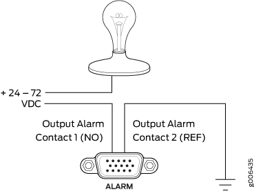
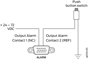
Figure 2 shows an example of a wiring diagram for a simple input alarm-reporting device. In this case the push button switch is an alarm sensor that triggers an input alarm when a door-open condition occurs.
See Also
Clocking Ports on the ACX1000 and ACX1100 Router
The clocking ports acquire the clock source and synchronize communication over time-division multiplexing (TDM) interfaces in the router. The clocking ports distribute a synchronized clock signal throughout the router by locking onto a clock signal originating from an internal clock source or by connecting to an external clock source.
The reference clock inputs can be T1/E1 line clocks, Ethernet recovered clocks, IEEE 1588v2 recovered clocks, or xDSL NTU-R timing. Externally available reference clocks are BITS T1/E1 rate clocks, 1 pulse per second (PPS), and 10 MHz. The four SubMiniature B (SMB) connectors on the front panel of the router connect to external clock signal sources. The clocking ports provide the synchronized output clocks from any one of the above reference inputs based on the clock’s priority.
Internal clock sources within the ACX1000 and ACX1100 router include:
External building-integrated timing system (BITS) timing port
10-MHz SMB connectors (one input and one output)
1.544-MHz/2.048 MHz T1/E1 (RJ-48) ports for timing input or output
1 PPS SMB connectors (one input and one output)
Time-of-Day (TOD) RS232 port
SyncE support on RJ-45/SFP ports as timing input or output
Packet timing (IEEE 1588v2) includes:
Timing input when configured as Ordinary Clock (OC) or Boundary Clock (BC)
Timing output when configured as BC
See Also
Front Panel of an ACX1000 Router
The front panel of an ACX1000 router consists of the following components (see Figure 3):
Chassis status LED labeled SYS
DC power terminals
USB port for upgrading Junos OS
Management Ethernet port labeled MGMT
Console or auxiliary port labeled CONSOLE/AUX
Alarm contact port labeled ALARM—accepts a DE-15 alarm cable
External clocking input port labeled EXT REF CLK IN
External clocking ports supporting 1PPS and 10MHz input and output
Network ports and corresponding status LEDs:
Eight T1/E1 ports labeled 0/0/0 through 0/0/7
Eight Gigabit Ethernet RJ-45 ports labeled 0/1/0 through 0/1/7
Combination Gigabit Ethernet ports labeled 0/2/0 through 0/2/3, either:
Four Gigabit Ethernet RJ-45 ports labeled Cu
Four Gigabit Ethernet ports labeled SFP that accept SFP transceivers
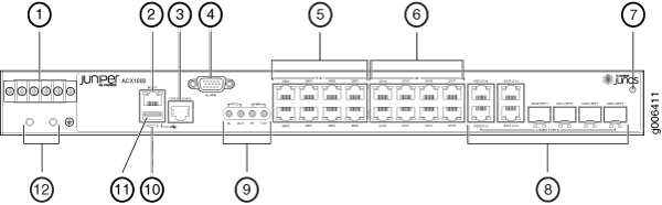
1 — DC terminals | 7 — ESD point |
2 — Management Ethernet port | 8 — Combination Gigabit Ethernet RJ-45 and SFP ports |
3 — Console or auxiliary port | 9 — External clocking ports |
4 — Alarm contact port | 10 — System (SYS) LED |
5 — T1/E1 ports | 11 — USB port |
6 — Gigabit Ethernet (GE) ports | 12 — Grounding terminals |
See Also
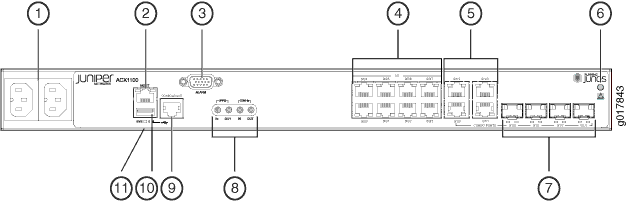
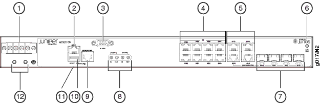
Front Panel of an ACX1100 Router
The front panel of an ACX1100 router consists of the following components (see Figure 4 and Figure 5):
Chassis status LED labeled SYS
AC power inlets or DC power terminals
USB port for upgrading Junos OS
Management Ethernet port labeled MGMT
Console or auxiliary port labeled CONSOLE/AUX
Alarm contact port labeled ALARM—accepts a DE-15 alarm cable
External clocking input port labeled EXT REF CLK IN
External clocking ports supporting 1PPS and 10MHz input and output
Network ports and corresponding status LEDs:
Eight Gigabit Ethernet (GE) RJ-45 ports labeled 0/0/0 through 0/0/7
Combination ports labeled 0/1/0 through 0/1/3, either:
Four Gigabit Ethernet RJ-45 ports
Four Gigabit Ethernet SFP ports that accept SFP transceivers
1 — AC inlets | 7 — Combination Gigabit Ethernet SFP ports |
2 — Management Ethernet port | 8 — External clocking ports |
3 — Alarm contact port | 9 — Console or auxiliary port |
4 — Gigabit Ethernet (GE) ports | 10 — USB port |
5 — Combination Gigabit Ethernet RJ-45 ports | 11 — System (SYS) LED |
6 — ESD point |
1 — DC terminals | 7 — Combination Gigabit Ethernet SFP ports |
2 — Management Ethernet port | 8 — External clocking ports |
3 — Alarm contact port | 9 — Console or auxiliary port |
4 — Gigabit Ethernet (GE) ports | 10 — USB port |
5 — Combination Gigabit Ethernet RJ-45 ports | 11 — System (SYS) LED |
6 — ESD point | 12 — Grounding terminals |
See Also
Uplink Ports on ACX1000 and ACX1100 Routers
Unless otherwise specified, the information about uplink ports applies to both ACX1000 and ACX1100 routers.
You can find information about the pluggable transceivers supported on your Juniper Networks device by using the Hardware Compatibility Tool. In addition to transceiver and connector type, the optical and cable characteristics—where applicable—are documented for each transceiver. The Hardware Compatibility Tool allows you to search by product, displaying all the transceivers supported on that device, or category, displaying all the transceivers by interface speed or type. The Hardware Compatibility Tool is located at https://apps.juniper.net/hct/.
The list of supported transceivers for the ACX1000 is located at https://pathfinder.juniper.net/hct/product/#prd=ACX1000. The list of supported transceivers for the ACX1100 is located at https://pathfinder.juniper.net/hct/product/#prd=ACX1100.
T1/E1 Ports
The ACX1000 router has eight T1/E1 ports located on the front panel. Table 2 describes the ports in more detail.
Feature |
Description |
|---|---|
Line rate |
E1: 2.048 Mbps per channel T1: 1.544 Mbps per channel |
Encapsulation |
TDM (SAToP) mode ATM PWE3/ATM IMA Mode |
Framing |
Superframe (D4) Extended superframe (ESF) Framed clear channel |
Diagnostic features |
T1/E1 T1 FDL CSU BERT JIT |
Cable |
Category 5 shielded twisted pair |
Connector |
100-ohm RJ-48 connector |
Port numbering (hardware) |
0/0/0 through 0/0/7 |
Port numbering (software) |
T1 framing (default): E1 framing: |
Gigabit Ethernet RJ-45 Ports
Each ACX1000 and ACX1100 router has twelve Gigabit Ethernet RJ-45 ports. Table 3 describes the ports in more detail.
Feature |
Description |
|---|---|
Supported standards |
|
Cable |
Category 5 |
Connector |
RJ-45 |
Port numbering (hardware) |
ACX1000: 0/1/0 through 0/1/7 and 0/2/0 (Cu) through 0/2/3 (Cu) ACX1100: 0/0/0 through 0/0/7 and 0/1/0 through 0/1/3 |
Port numbering (software) |
ACX1000: ACX1100: |
Gigabit Ethernet SFP Ports
The Gigabit Ethernet SFP ports described in Table 4 are located on the front of the chassis allow you to install small form-factor pluggable (SFP) transceivers.
Feature |
Description |
|---|---|
Supported standards |
See the Hardware Compatibility Tool for the specifications of transceivers supported on the ACX1000 or ACX1100. The list of supported transceivers for the ACX1000 is located at https://pathfinder.juniper.net/hct/product/#prd=ACX1000. The list of supported transceivers for the ACX1100 is located at https://pathfinder.juniper.net/hct/product/#prd=ACX1100. |
Cable |
|
Connector |
|
Port numbering (hardware) |
|
Port numbering (software) |
|
See Also
LEDs on ACX1000 and ACX1100 Routers
Unless otherwise specified, the information about LEDs applies to both ACX1000 and ACX1100 routers.
- System LED on the Front Panel
- T1/E1 Port LEDs
- Ethernet Port LEDs
- SFP Port LEDs
- Management and Console Port LEDs on the Front Panel
System LED on the Front Panel
One bicolor LED labeled SYS indicates the status of the router. Table 5 describes the system LED in more detail.
Label |
Color |
State |
Description |
|---|---|---|---|
SYS |
Green |
Blinking |
Router is transitioning online. |
On steadily |
Router is functioning normally. |
||
Red |
Blinking |
Router has reported an alarm. |
|
On steadily |
Router has failed. |
T1/E1 Port LEDs
The front panel of the ACX1000 router has eight T1/E1 ports, each with one pair of port LEDs. Table 6 describes the LEDs in more detail.
Name |
Location |
Color |
Description |
|---|---|---|---|
Link |
Left |
Green |
Online with no alarms or failures. |
Red |
Active with a local alarm; router has detected a failure. |
||
– |
Not enabled. |
||
Link (remote alarms) |
Right |
Yellow |
Online with alarms for remote failures. |
Ethernet Port LEDs
Each Gigabit Ethernet RJ-45 port on the front panel of the router has one pair of port LEDs. Table 7 describes the LEDs in more detail.
Name |
Location |
Color |
State |
Description |
|---|---|---|---|---|
Link |
Right |
Amber |
On |
Link is online. |
– |
Off |
No link. |
||
RX |
Left |
Green |
Blinking |
The port is receiving data. |
– |
Off |
The port is not receiving data. |
SFP Port LEDs
The front panel has four Gigabit Ethernet SFP ports, each with one pair of port LEDs. Table 8 describes the LEDs in more detail.
Name |
Location |
Color |
State |
Description |
|---|---|---|---|---|
Link |
Right |
Amber |
On |
Link is online. |
– |
Off |
No link. |
||
RX |
Left |
Green |
Blinking |
The port is receiving data. |
– |
Off |
The port is not receiving data. |
Management and Console Port LEDs on the Front Panel
Two RJ-45 ports labeled MGMT and CONSOLE/AUX each have a pair of LEDs that display the status of the port. Table 9 describes the LEDs in more detail.
Name |
Location |
Color |
State |
Description |
|---|---|---|---|---|
Link/Activity |
Right |
Amber |
On |
Link is online. |
Yellow |
Blinking |
Indicates link activity. |
||
– |
Off |
No link. |
||
RX |
Left |
Green |
Blinking |
The port is receiving data. |
– |
Off |
The port is not receiving data. |