Launch and Deploy vSRX Virtual Firewall in Nutanix AHV Cluster
Before you begin, you need a Nutanix account and an Identity and Access Management (IAM) role, with all required permissions to access, create, modify, and delete Nutanix cloud objects. You should also create access keys and corresponding secret access keys, X.509 certificates, and account identifiers. For better understanding of Nutanix terminologies and their use in vSRX Virtual Firewall deployments, see Understanding vSRX with Nutanix.
The topics in this section help you launch vSRX Virtual Firewall instances in a Nutanix AHV cluster.
Log In to Nutanix Setup
This topic provide details on how to log in to Nutanix setup.
To access the Nutanix management console, remote access must be enabled on your local machine.
Once you have logged in to the remote Windows machine, you can access the Nutanix Prims Enable using your Web browser.
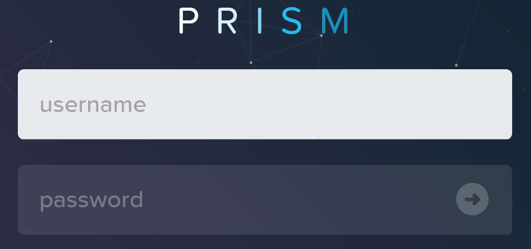
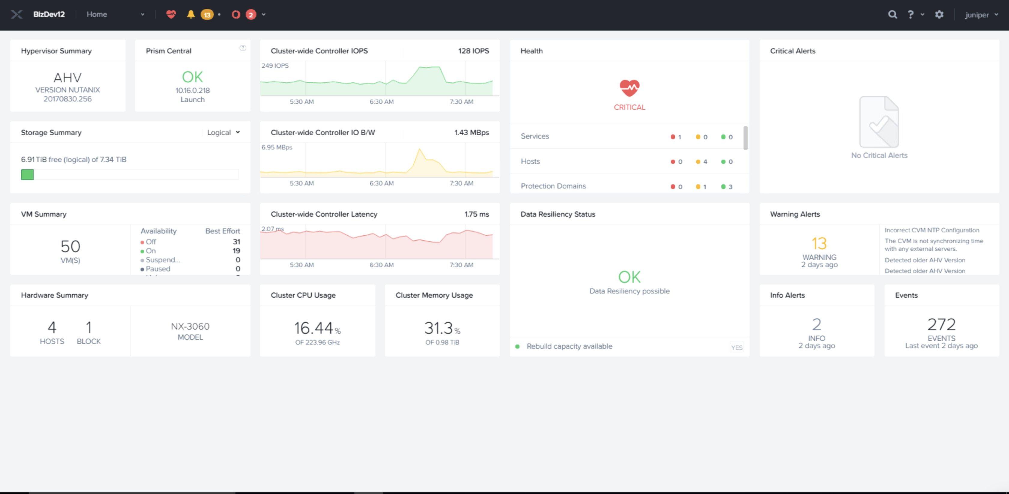
After you provide login details, the Nutanix Prism home page appears.
Adding a vSRX Virtual Firewall Image
Before you create a vSRX Virtual Firewall image, copy the image in the local machine from which the image can be accessed by Nutanix Prism Element. After copying, locally source the images from Prism GUI.
All the required vSRX Virtual Firewall images are available in the Juniper download page. After you copy the vSRX Virtual Firewall image on the local machine, complete the following steps to upload the image in Nutanix:
- Click the Image configuration option from the Tool menu in the on top-right corner of the Prism home page.
- Click the Upload Image tab.
- Enter the required image details and provide a local file path under Image source. Wait for the image to be uploaded successfully.
Network Creation
This topic provides details on configuring the network for deploying vSRX Virtual Firewall VMs.
You can create a Routing Engine-FPC (RE-FPC) (or any other network) using the following steps:
In this deployment guide, all the the networks created on Nutanix setup are VLAN-based networks. Therefore, if you are deploying a Routing Engine and FPC on different hosts (compute nodes), the VLAN that is used by the RE-FPC internal networks must be part of the allowable VLAN range that is configured on the top-of-rack switch connecting the two machines.
We tested the use case in which the Routing Engine and FPC were deployed on different hosts. However, for all our other tests, we deployed the Routing Engine and FPC on the same host.
Create and Deploy a vSRX Virtual Firewall VM
This topic provides details on how to deploy a vSRX Virtual Firewall VM.
In Acropolis-managed clusters, you can create a new virtual machine (VM) through the Web console. When creating a VM, you can configure all of its components, such as number of vCPUs and memory, but you cannot attach a volume group to the VM. Attaching a volume group is possible only when you are modifying a VM.
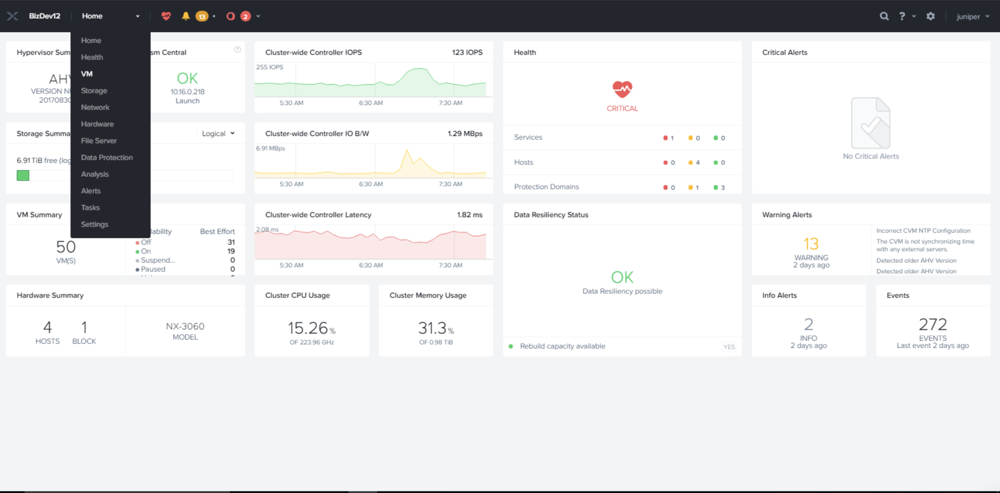
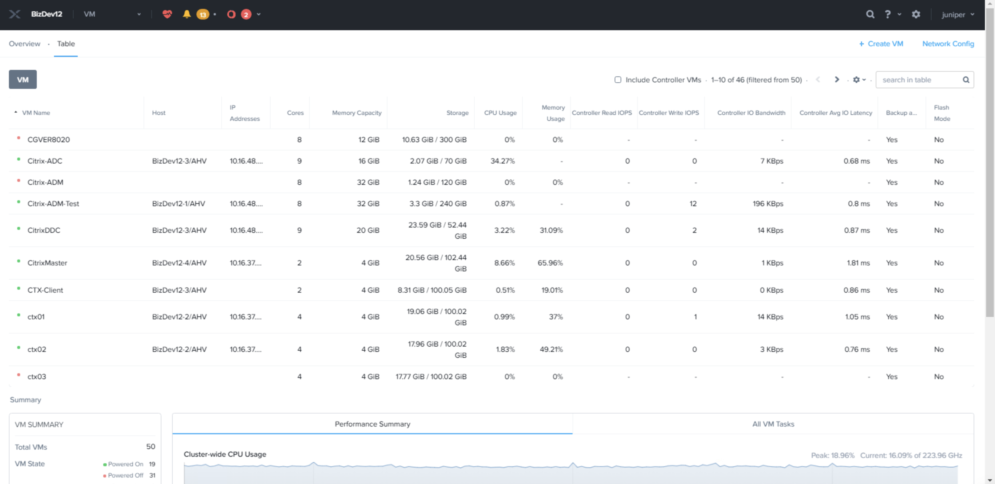
- Click the Home menu at the top of the Prism
home page and select the VM option from the drop-down list
as as shown in Figure 3.Figure 3: VM Option Page
- To create a VM, select the VM option under
the Home tab (top-left corner) and click + Create VM at
the top-right side of the VM page as shown in Figure 4.Figure 4: VM Page
The Create VM page appears as shown in Figure 5.
-
On the Create VM page, provide details of the
indicated fields to create a vSRX Virtual Firewall
VM as shown in Figure 5 and click the Save
button.
-
Name: Enter a name for the VM.
-
Description (optional): Enter a description for the VM.
-
vCPU(s): Enter the number of virtual CPUs to allocate to this VM.
-
Number of Cores per vCPU: Enter the number of cores assigned to each virtual CPU.
-
Memory: Enter the amount of memory to allocate to this VM.
-
Select the time zone and update the compute details.
Figure 5: Create VM Page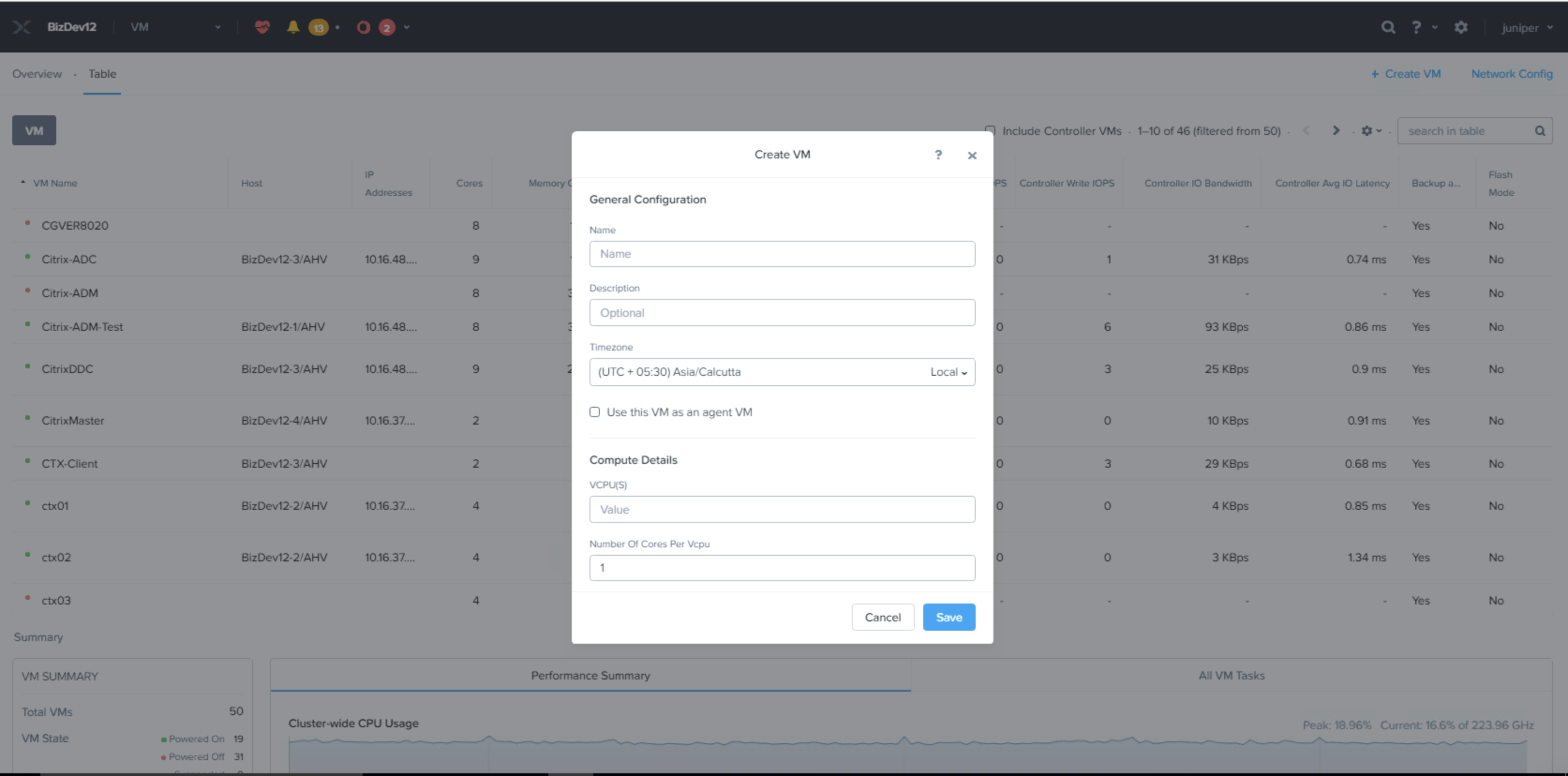 Figure 6: VM Compute Details Page
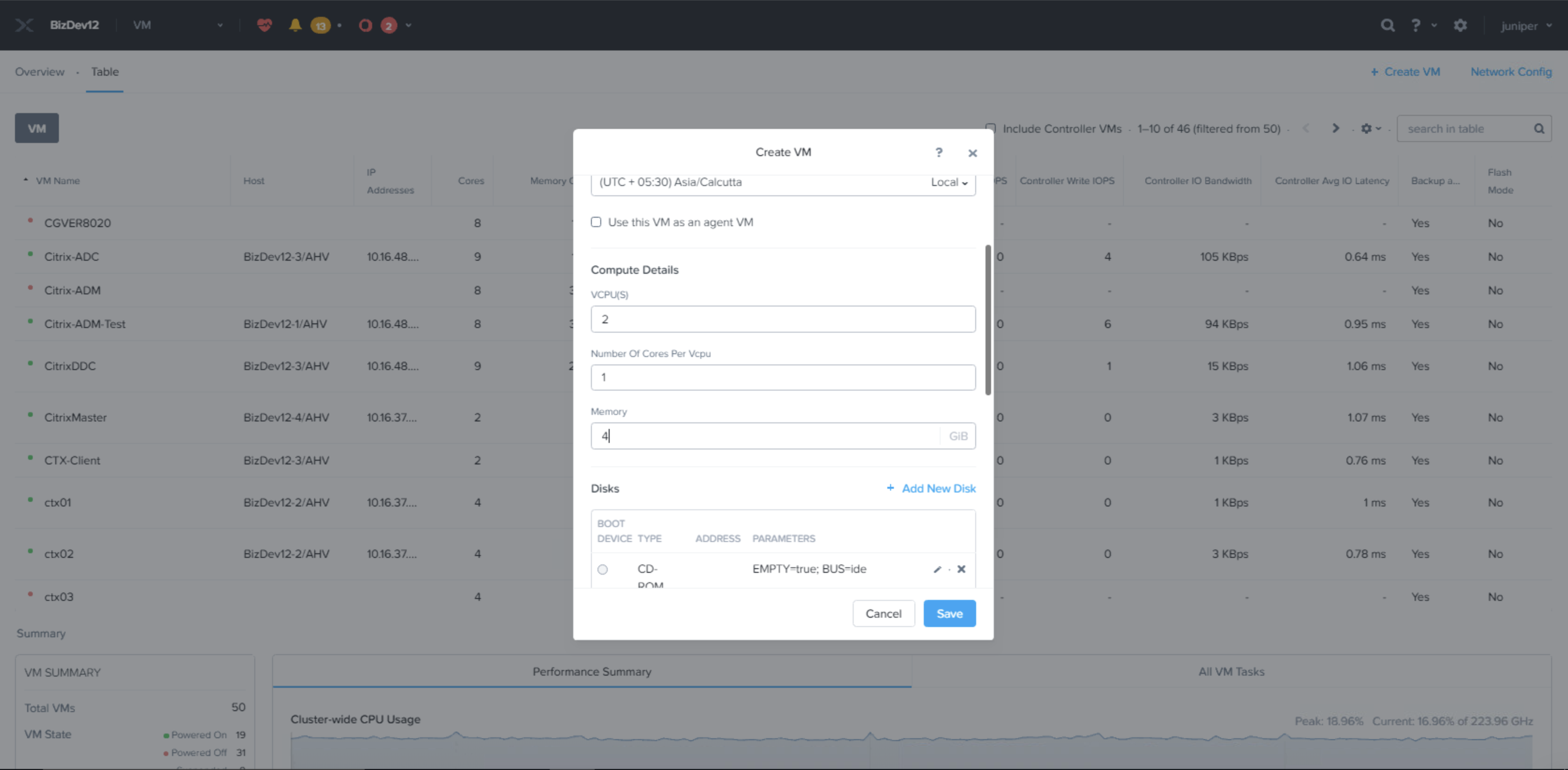
-
-
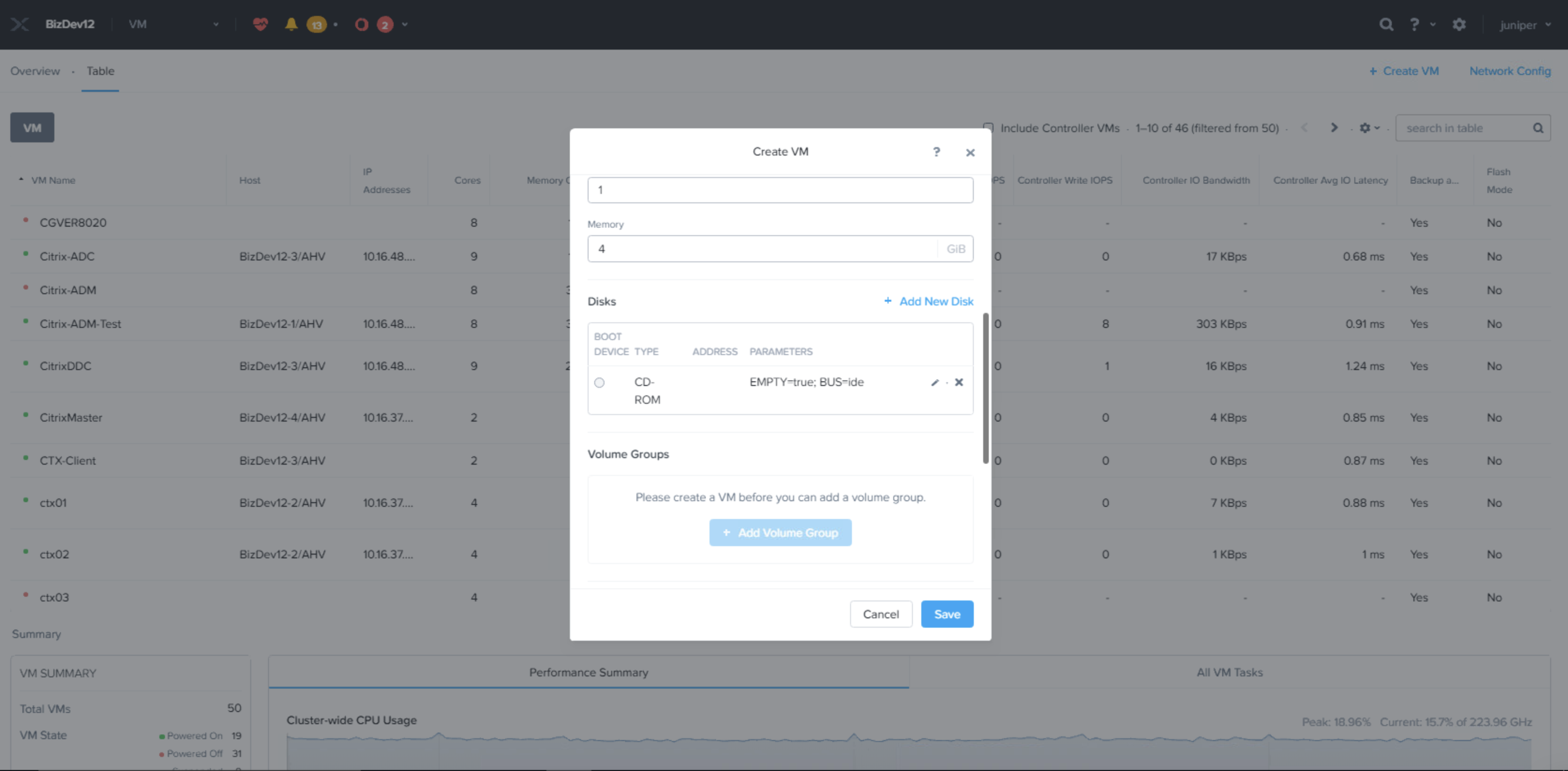
To attach a disk to the vSRX Virtual Firewall
VM, click the + Add New Disk
option on the Create
VM page as shown in Figure 7.
Figure 7: VM Disk Details Page
-
The Add Disk page
appears as shown in Figure 8. Select the vSRX Virtual Firewall Junos
Image.
Do the following in the indicated fields and click on the Add button:
-
Type: Select the type of storage device, DISK or CDROM, from the drop-down list. The following fields and options vary depending on whether you choose DISK or CDROM.
-
Operation: Specify the device contents from the drop-down list.
-
Select Clone from ADSF file to copy any file from the cluster that can be used as an image onto the disk.
-
Select Empty CDROM to create a blank CD device. (This option appears only when CD is selected in the previous field.) A CD device is needed.
-
Select Allocate on Container to allocate space without specifying an image. (This option appears only when DISK is selected in the previous field.) Selecting this option means you are allocating space only. You have to provide a system image later from a CD or other source.
-
Select Clone from Image Service to copy an image that you have imported by using the image service feature onto the disk.
-
-
Bus Type: Select the bus type from the drop-down list. The choices are IDE, SCSI, or SATA.
-
Path: Enter the path to the desired system image.
Note:Field for entering the path appears only when Clone from ADSF file is selected. This file specifies the image to copy. For example, enter the pathname as /container_name/iso_name.iso. For example to clone an image from myos.iso in a container named crt1, enter /crt1/myos.iso. When a user types the container name (/container_name/), a list appears of the ISO files in that container (If one or more ISO files had previously been copied to that container).
-
Image: Select the image that you have created by using the image service feature. This field appears only when Clone from Image Service is selected. This field specifies the image to copy.
-
Size: Enter the disk size in GiBs. This field appears only when Allocate on Container is selected.
-
When all the field entries are correct, click the Add button to attach the disk to the VM and return to the Create VM page.
-
Repeat Step 5 to attach additional devices to the VM.
Figure 8: Add Disk Details Page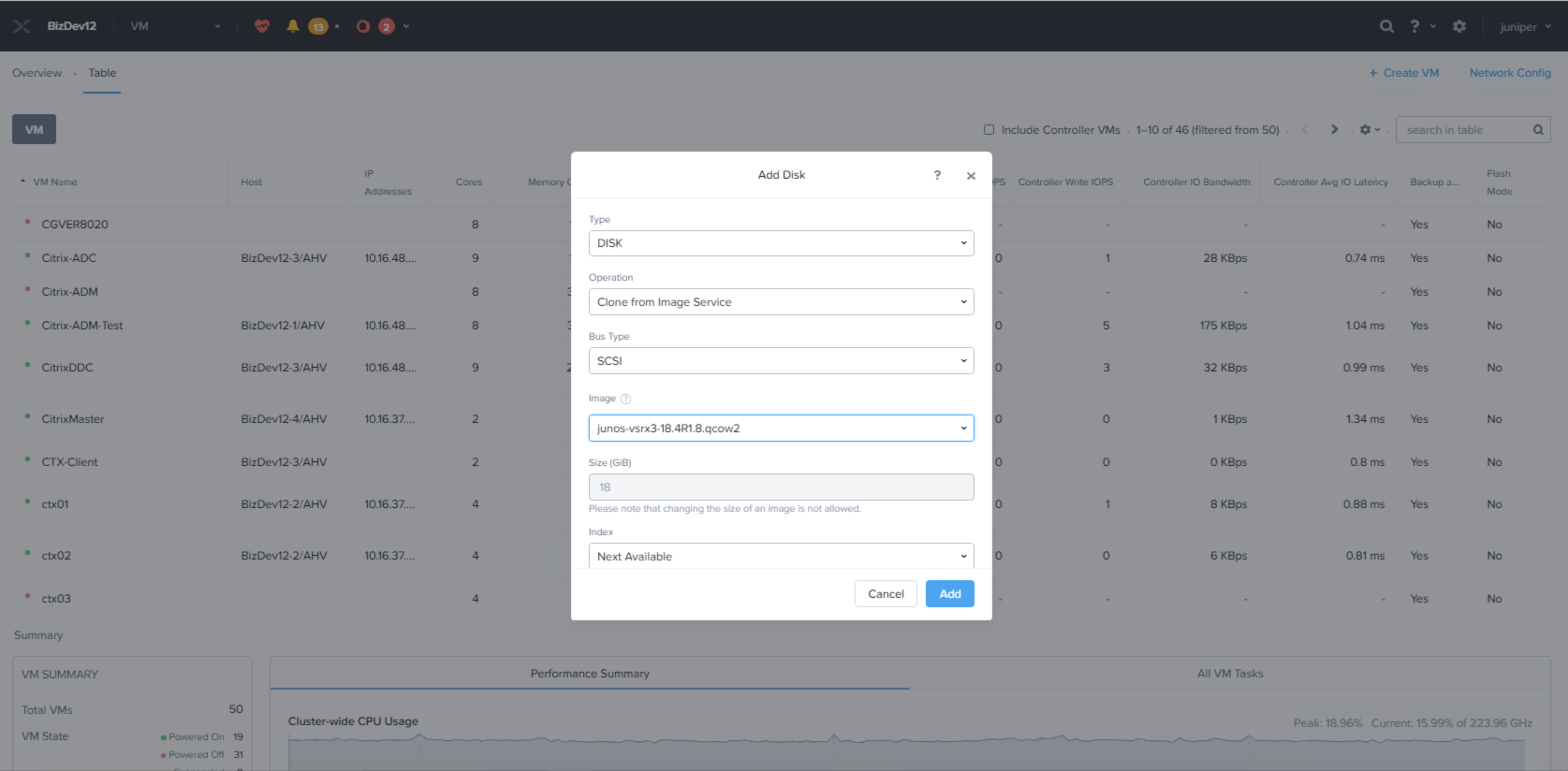
-
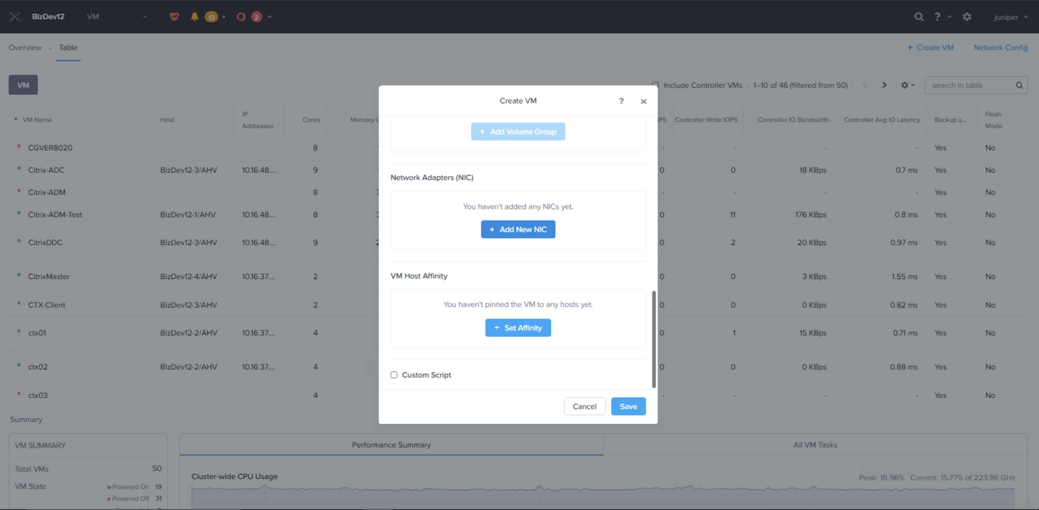
-
To create a network interface for the vSRX
Virtual Firewall VM, click the + Add
New NIC option in the Create VM page
as shown in Figure 9. Add the NICs required.
Figure 9: Add New NIC Option
The Create NIC page appears as shown in Figure 10. Do the following in the indicated fields:
-
VLAN Name: Select the target virtual LAN from the drop-down list.
-
VLAN ID: This is a read-only field that displays the VLAN ID.
-
VLAN UUID: This is a read-only field that displays the VLAN UUID.
-
Network Address/Prefix: This is a read-only field that displays the network IP address and prefix.
-
IP Address: Enter an IP address for the VLAN. This field appears only if the NIC is placed in a managed network. Entering an IP address in this field is optional when the network configuration provides an IP pool. If the field is left blank, the NIC is assigned an IP address from the pool.
-
When all the field entries are correct, click the Add button to create a network interface for the VM and return to the Create VM page.
-
Repeat this Step 6 to create additional network interfaces for the VM.
Figure 10: Create NIC Page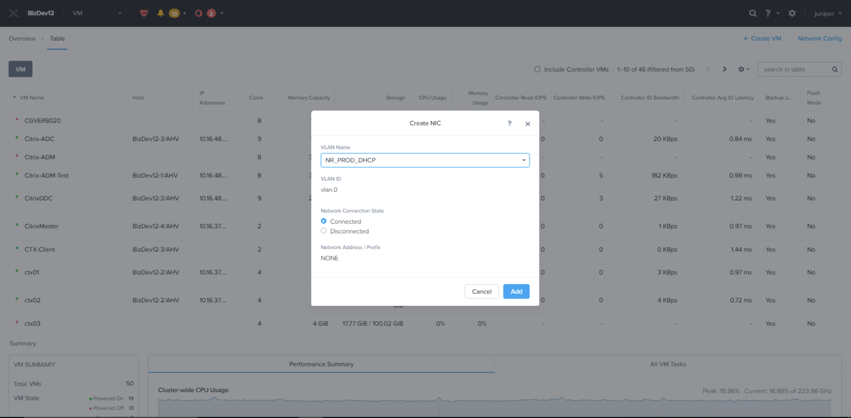
Repeat Step 6 and add more VLANs and NICs as needed.
Figure 11: Adding More VLANs and NICs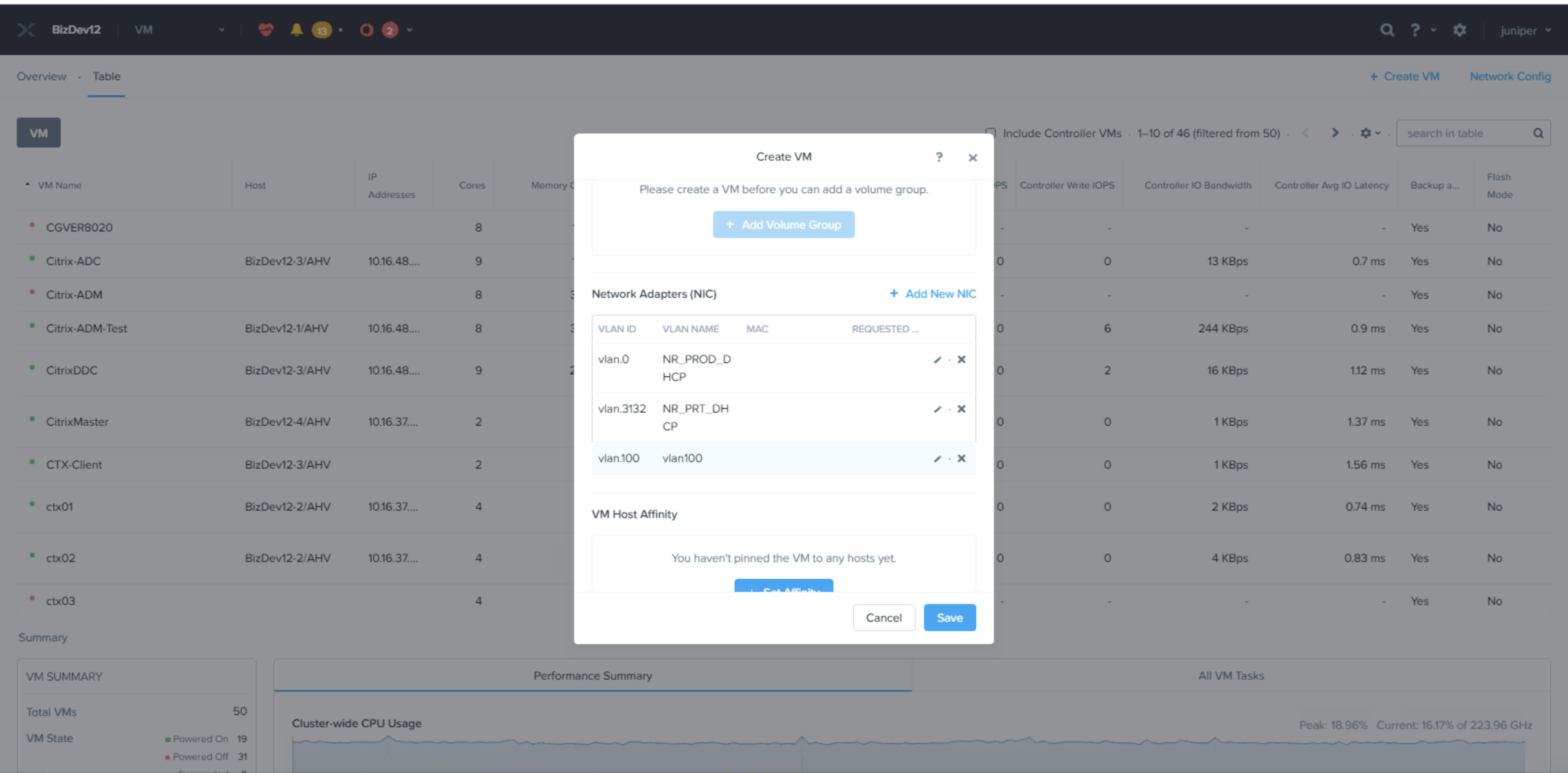
-
- (Optional) If host affinity is needed, click Set
Affinity..Figure 12: VM Host Affinity Page
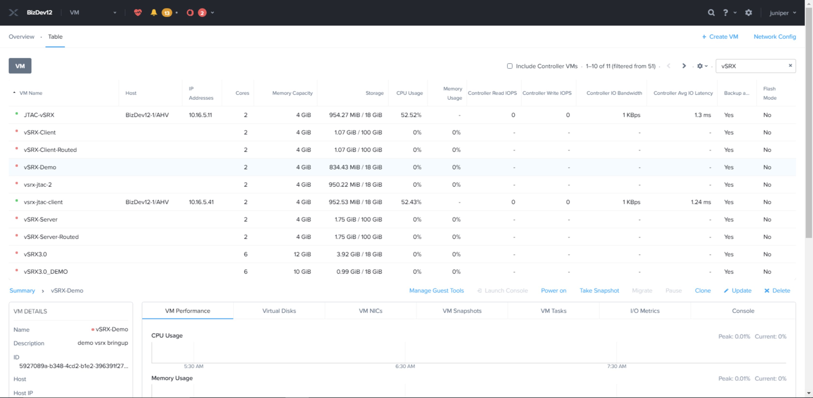
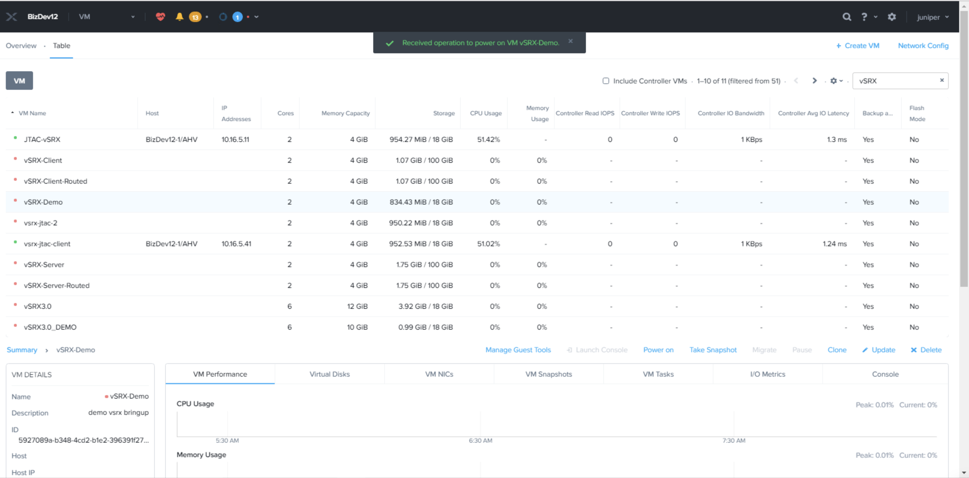
Power on the vSRX Virtual Firewall VMs
This topic provides you details on how to power on vSRX Virtual Firewall VMs.
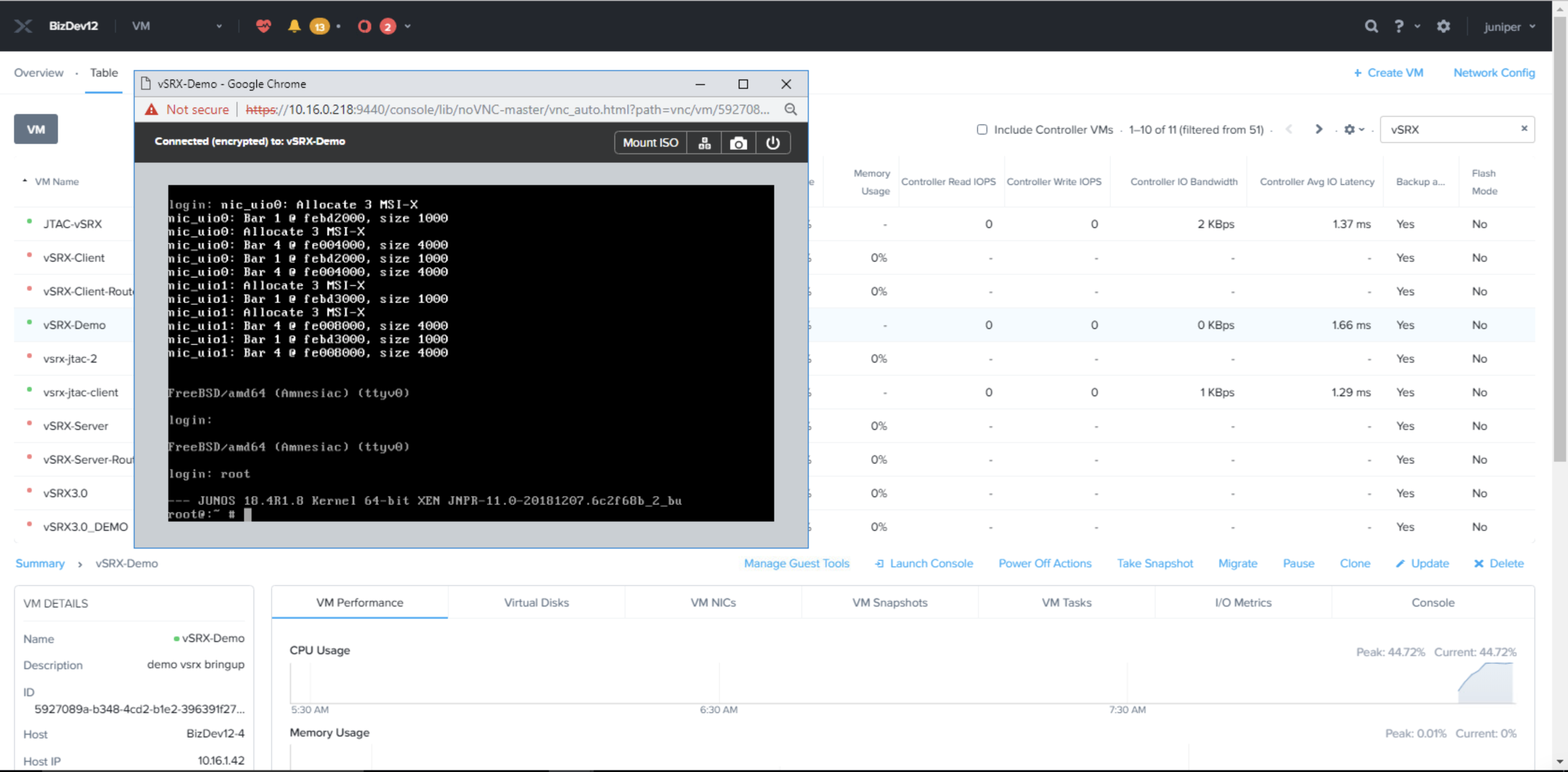
Launch vSRX Virtual Firewall VM Console
This topic explains how to launch the vSRX Virtual Firewall VM console.
Click the Launch Console option at the bottom of screenshot as shown in Figure 15 to launch the VM console.