Add vSRX Virtual Firewall Interfaces
The Hyper-V virtual switch is a software-based Layer 2 Ethernet network switch that connects VMs to either physical or virtual networks. A virtual switch can be configured from Hyper-V Manager or Windows PowerShell . The Hyper-V host uses the virtual switches to connect virtual machines to the internet through the host computer's network connection. You configure networking for the vSRX Virtual Firewall by adding, removing, and modifying its associated network adapters in the Hyper-V host as necessary.
To perform this procedure, you must have appropriate permissions. Contact your Virtual Server administrator to request the proper permissions to add a virtual switch and network adapter..
For the vSRX Virtual Firewall VM, you pair a network adapter with a virtual switch for the vSRX Virtual Firewall to receive and transmit traffic. You map network adapters to the specific vSRX Virtual Firewall interfaces: Network adapter 1 is mapped to the fxp0 (out-of-band management) interface, network adapter 2 is mapped to the ge-0/0/0 (revenue) interface, network adapter 3 is mapped to ge-0/0/1, and so on (see Requirements for vSRX on Microsoft Hyper-V). Hyper-V supports a maximum of eight network adapters.
When adding virtual switches, there are no limits imposed by Hyper-V. The practical limit depends on the available computing resources.
This section includes the following topics on adding vSRX Virtual Firewall interfaces in Hyper-V:
Add Virtual Switches
To add virtual switches for the vSRX Virtual Firewall VM using the Virtual Switch Manager in the Hyper-V Manager:
- Under the Virtual Switches section, select New virtual
network switch. The Create Virtual Switch pane appears (see Figure 1).Figure 1: Create Virtual Switch Pane
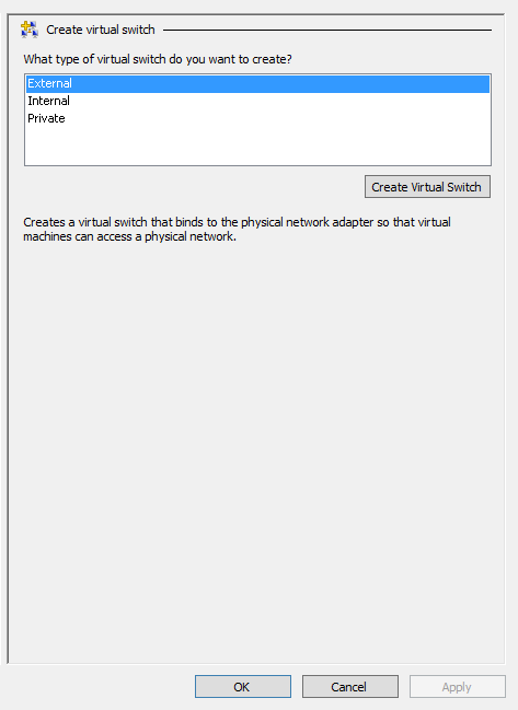
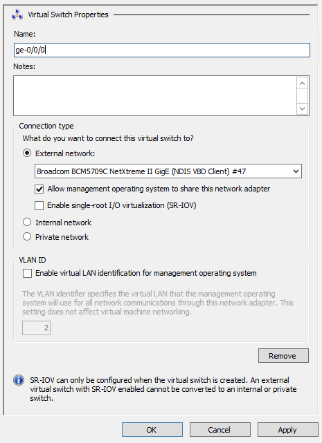
- Select Create Virtual Switch. The Virtual
Switch Properties pane appears (see Figure 2).Figure 2: Virtual Switch Properties Pane
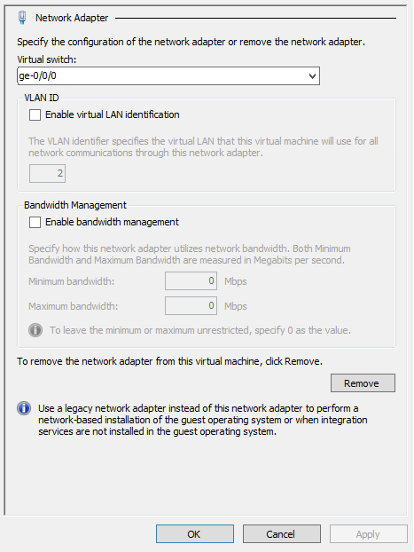
- From the Virtual switch drop-down list, select the virtual switch that you want to assign
to this network adapter. See Requirements
for vSRX on Microsoft Hyper-V for a summary of interface
names and mappings for a vSRX Virtual Firewall VM.Figure 3: Adding Virtual Switch to Network Adapter Example
- If a network adapter is to be used as an interface for
Layer 2 mode support
on the vSRX Virtual Firewall, then from the Network Adapter pane select Advanced
Features. Select the Enable MAC address spoofing check box to enable the MAC address spoofing function for the network
adapter (see Figure 4).
MAC address spoofing allows each network adapter to change its source MAC address for outgoing packets to one that is not assigned to them. Enabling MAC address spoofing ensures those packets are not dropped by the network adapter if the source MAC address fails to match the outgoing interface MAC address.
Figure 4: Network Adapter Enable MAC Address Spoofing Example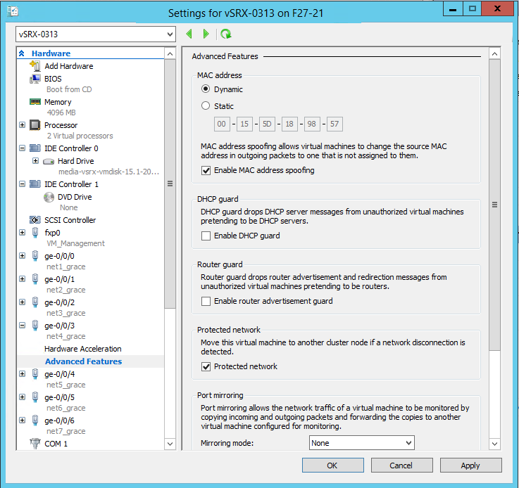
See Also
Configure the vSRX Virtual Firewall to Use a VLAN
Hyper-V supports the configuration of VLANs on a network adapter in the host computer. For each network adapter that you configure for the vSRX Virtual Firewall VM, if required, you can add a VLAN identifier to specify the VLAN that the vSRX Virtual Firewall VM will use for all network communications through the network adapter.
By default, Hyper-V enables trunk mode for a VLAN. Trunk mode allows multiple VLAN IDs to share a connection between the physical network adapter and the physical network.
To give the vSRX Virtual Firewall VM external access on the virtual network in multiple VLANs, you will need to configure the port on the physical network to be in trunk mode. You will also need to know the specific VLANs that are used and all of the VLAN IDs used by the virtual machines that the virtual network supports.
To utilize a Hyper-V VLAN, ensure that you are using a physical network adapter that supports 802.1q VLAN tagging. By default, the virtual network adapter in Hyper-V is in untagged mode and you might need to enable the feature on a virtual network adapter.
By using Windows PowerShell, you can determine the mode
of the vNIC (Get-VmNetworkAdapterVlan command) and change
the mode of the vNIC (Set-VmNetworkAdapterVlan command).
See Get-VMNetworkAdapterVlan and Set-VMNetworkAdapterVlan for details on both Windows PowerShell
virtual network adapter commands.
To add a VLAN for a vSRX Virtual Firewall VM virtual network adapter:
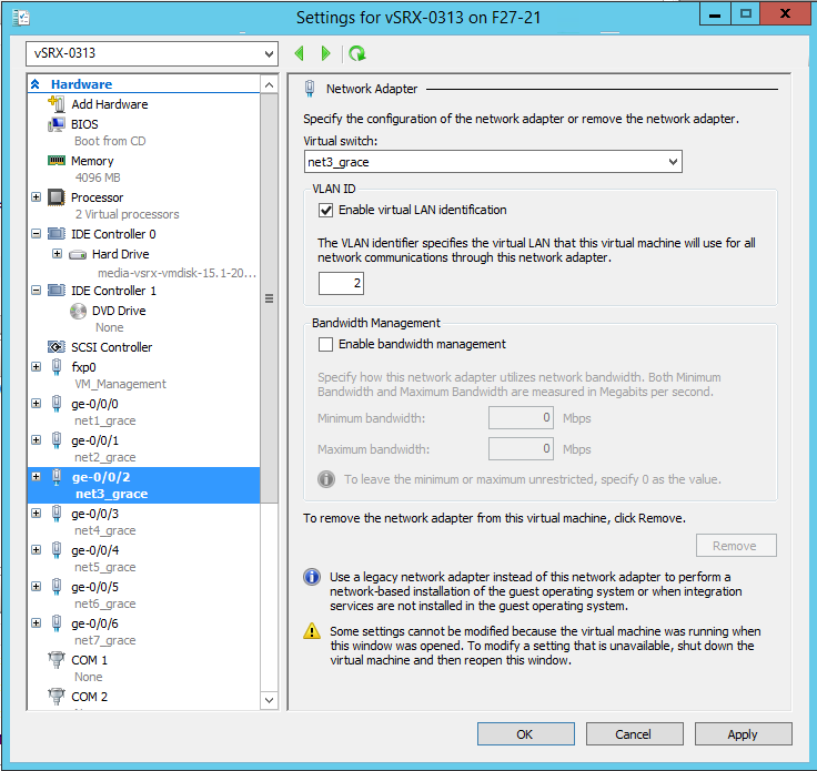
- Select Enable virtual LAN identification, and
then enter the VLAN ID you intend to use (see Figure 5). You can change
the VLAN ID to any number or leave the default. This is the VLAN identification
number that the vSRX Virtual Firewall will use for all network communication through
this network adapter. Figure 5: Enable VLAN Identification Example