ON THIS PAGE
vSRX Virtual Firewall Cluster Staging and Provisioning in Hyper-V
Staging and provisioning a vSRX Virtual Firewall cluster on a Hyper-V host computer includes the following tasks:
Starting in Junos OS Release 15.1X49-D100 and Junos OS Release 17.4R1, support for chassis clustering to provide network node redundancy is only available on Windows Hyper-V Server 2016.
Deploying the VMs and Additional Network Adapters in Hyper-V
The vSRX Virtual Firewall cluster uses three interfaces exclusively for clustering (the first two are predefined):
Out-of-band management interface (fxp0).
Cluster control link (em0).
Cluster fabric links (fab0 and fab1). For example, you can specify ge-0/0/0 as fab0 on node0 and ge-7/0/0 as fab1 on node1.
A cluster requires three interfaces (two for the cluster and one for management) and additional interfaces to forward data. This section outlines how to create the control link and fabric link connections, and to map all data interfaces to network adapters.
For an overview on the procedure to add virtual switches and map the virtual switch to a network adapter, see Add vSRX Interfaces
Creating the Control Link Connection in Hyper-V
To connect the control interface through the control link virtual switch using Hyper-V Manager:
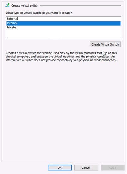
- Under the Virtual Switches section, select New virtual
network switch. The Create Virtual Switch pane appears (see Figure 1).Figure 1: Create Virtual Switch Pane
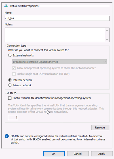
- Select Create Virtual Switch. The Virtual
Switch Properties page appears (see Figure 2).Figure 2: Virtual Switch Properties Pane
- Right-click the vSRX Virtual Firewall VM and select Settings from the context menu. From the Settings dialog for the vSRX Virtual Firewall VM,
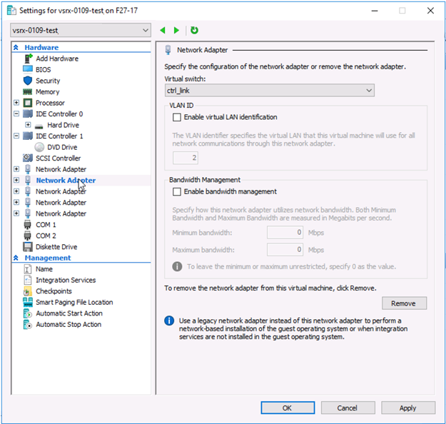
the Hardware section, click Network Adapter. The Network
Adapter pane appears (see Figure 3). Assign
network adapter 2 as the control link (em0) virtual switch.Figure 3: Adding Virtual Switch to Network Adapter Pane Example
Creating the Fabric Link Connection in Hyper-V
To connect the fabric interface through the fabric link virtual switch using Hyper-V Manager
- If necessary, open the Hyper-V Manager by selecting Start > Administrative Tools > Hyper-V Manager.
- From the Hyper-V Manager, select Action > Virtual Switch Manager. The Virtual Switch Manager appears.
- Under the Virtual Switches section, select New virtual network switch. The Create Virtual Switch pane appears (see Figure 1).
- Select Internal as the type of virtual switch. Internal allows communication between virtual machines on the same Hyper-V server, and between the virtual machines and the management host operating system.
- Select Create Virtual Switch. The Virtual Switch Properties page appears (see Figure 2).
- Specify a name for the fabric link virtual switch. Leave the other virtual switch properties at their default settings.
- Click OK and then click Yes to apply networking changes and to close the Virtual Switch Manager window.
- Right-click the vSRX Virtual Firewall VM and select Settings from the context menu. From the Settings dialog for the vSRX Virtual Firewall VM, the Hardware section, click Network Adapter to access the Network Adapter pane. The Network Adapter pane appears (see Figure 3). Assign network adapter 3 as the fabric link (fab 0 or fab 1) virtual switch.
- From the Virtual switch drop-down assign fab0 or fab1 to the fabric link virtual switch.
- From the Network Adapter pane, select Advanced Features. Select the Enable MAC address spoofing check box to enable the MAC address spoofing function for the network adapter. MAC address spoofing is a requirement for the fabric link interface included in the redundancy groups.
- Click OK and then click Yes to apply network adapter changes.
Creating the Data Interfaces Using Hyper-V
To map all data interfaces to the desired network adapters:
- If necessary, open the Hyper-V Manager by selecting Start > Administrative Tools > Hyper-V Manager.
- From the Hyper-V Manager, select Action > Virtual Switch Manager. The Virtual Switch Manager appears.
- Under the Virtual Switches section, select New virtual network switch. The Create Virtual Switch pane appears (see Figure 1).
- Select Internal as the type of virtual switch. Internal allows communication between virtual machines on the same Hyper-V server, and between the virtual machines and the management host operating system.
- Select Create Virtual Switch. The Virtual Switch Properties page appears (see Figure 2).
- Specify a name for the data interface virtual switch. Leave the other virtual switch properties at their default settings.
- Click OK and then click Yes to apply networking changes and to close the Virtual Switch Manager window.
- Right-click the vSRX Virtual Firewall VM and select Settings from the context menu. From the Settings dialog for the vSRX Virtual Firewall VM, the Hardware section, click Network Adapter to access the Network Adapter pane. The Network Adapter pane appears (see Figure 3). Assign network adapter 3 as the data interface (fab 0 or fab 1) virtual switch.
- From the Virtual switch drop-down assign data interface to the virtual switch.
- From the Network Adapter pane, select Advanced Features. Select the Enable MAC address spoofing check box to enable the MAC address spoofing function for the network adapter. MAC address spoofing is a requirement for the data interfaces included in the redundancy groups.
- Click OK and then click Yes to apply network adapter changes. The data interface will be connected through the data virtual switch.
Prestaging the Configuration from the Console
The following procedure explains the configuration commands required to set up the vSRX Virtual Firewall chassis cluster. The procedure powers up both nodes, adds the configuration to the cluster, and allows SSH remote access.
Connecting and Installing the Staging Configuration
After the vSRX Virtual Firewall cluster initial setup, set the cluster ID and the node ID, as described in Configure a vSRX Chassis Cluster in Junos OS.
After reboot, the two nodes are reachable on interface fxp0
with SSH. If the configuration is operational, the show chassis
cluster status command displays output similar to that shown
in the following sample output.
vSRX Virtual Firewall> show chassis cluster status
Cluster ID: 1
Node                  Priority          Status    Preempt  Manual failover

Redundancy group: 0 , Failover count: 1
    node0                   100         secondary      no       no
    node1                   150         primary        no       no

Redundancy group: 1 , Failover count: 1
    node0                   100         secondary      no       no
    node1                   150         primary        no       no
A cluster is healthy when the primary and secondary nodes are present and both have a priority greater than 0.
Change History Table
Feature support is determined by the platform and release you are using. Use Feature Explorer to determine if a feature is supported on your platform.