Certificate-Based Validation Using EAP-TLS Authentication
In this configuration, you use the EAP-TLS authentication method to validate the user certificates. You continue to use the username and password for external user authentication using the RADIUS server to download the initial configuration from the SRX Series Firewall.
We assume that you have completed the basic setup of your SRX Series Firewalls, including interfaces, zones, and security policies as illustrated in the Juniper Secure Connect Deployment Setup.
For information about prerequisites, see System Requirements for Juniper Secure Connect.
Ensure that you have a Public Key Infrastructure (PKI) configured as the backend authentication. In this case, you need to install the root certificate of the CA on each client as well as a user specific certificate on each client device. Note that local authentication is not supported in this scenario.
You must ensure that the SRX Series Firewall uses either a signed certificate or a self-signed certificate instead of the default system-generated certificate. Before you start configuring Juniper Secure Connect, it is important that you read the instructions in Get Started with Juniper Secure Connect.
Configure Juniper Secure Connect VPN Settings
To configure VPN settings using the J-Web interface:
-
Log in to your SRX Series Firewall using J-Web interface. Figure 1 shows
J-Web login page.
Figure 1: J-Web Access and Login
After logging in successfully, you land on the Basic Settings page. Figure 2 shows an example of the landing page.
Figure 2: J-Web Landing Page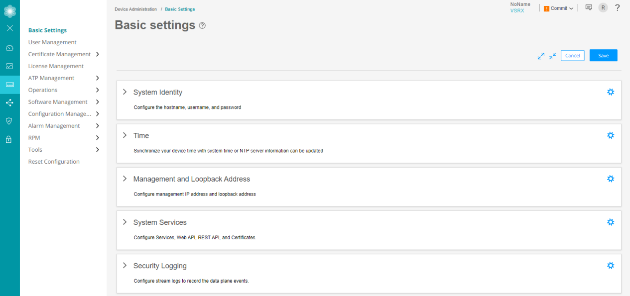
-
In the J-Web side pane, navigate to Network > VPN > IPsec
VPN.
-
After you click IPsec VPN, the IPsec VPN page appears. Figure 3 shows an example of the IPsec VPN page.
Figure 3: IPsec VPN Page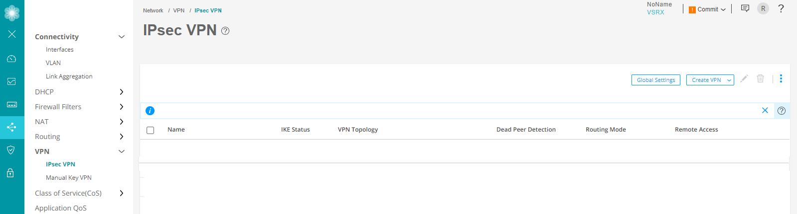
-
At the right corner of the page, select Create VPN > Remote Access > Juniper Secure Connect to create the IPsec VPN setting for Juniper Secure Connect.
The following warning message appears:
Figure 4: Warning Message To Generate And Bind Self-signed Certificate
As mentioned in the warning message, create a self-signed certificate and bind the certificate to the SRX Series Firewall. For more information, see Deploy Certificates for Juniper Secure Connect.
For detailed information about creating a remote access VPN, see Create a Remote Access VPN—Juniper Secure Connect.
-
Again navigate to Network > VPN > IPsec VPN and at the right corner of the page, select Create VPN > Remote Access > Juniper Secure Connect to create the IPsec VPN setting for Juniper Secure Connect. The Create Remote Access (Juniper Secure Connect) page appears. Figure 5 shows an example to create remote access VPN.
Figure 5: Create VPN - Remote Access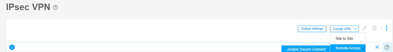
Figure 6 shows an example of the Create Remote Access page with Certificate-based authentication method.
Figure 6: Create Remote Access Page For Certificate-Based Authentication Method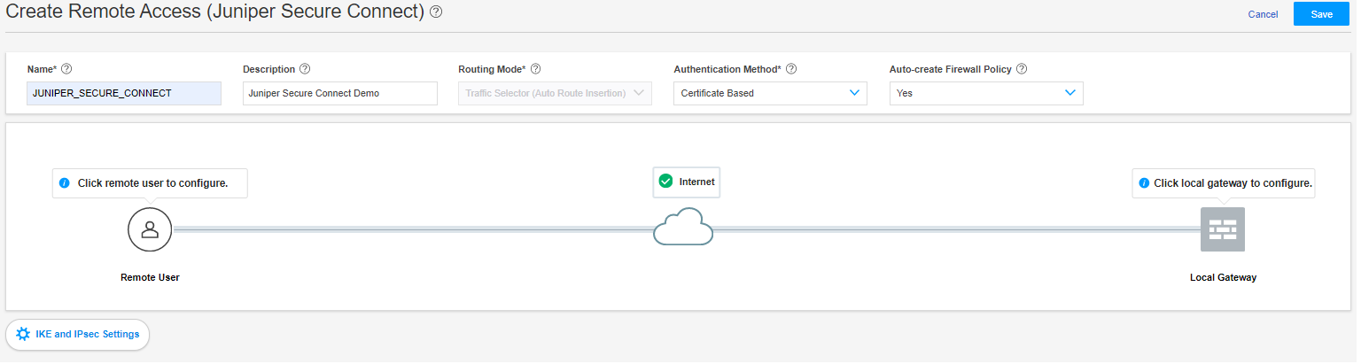
-
- On the Create Remote Access (Juniper Secure Connect) page
(see Figure 7):
Enter the name for the Remote Access Connection (this is, the name that will be displayed on the End Users Realm Name in Juniper Secure Connect application) and a description.
The routing mode is set to Traffic Selector (Auto Route Insertion) by default.
Select the authentication method. For this example, let’s select Certificate Based from the drop-down list.
Select Yes to create the firewall policy automatically using Auto-create Firewall Policy option.
Figure 7: Certificate-Based Authentication Method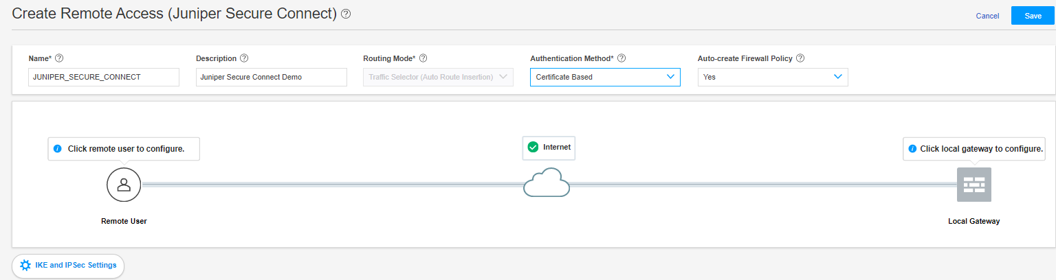
- Click Remote User icon to configure the Juniper
Secure Connect application settings.Figure 8: Remote User Page
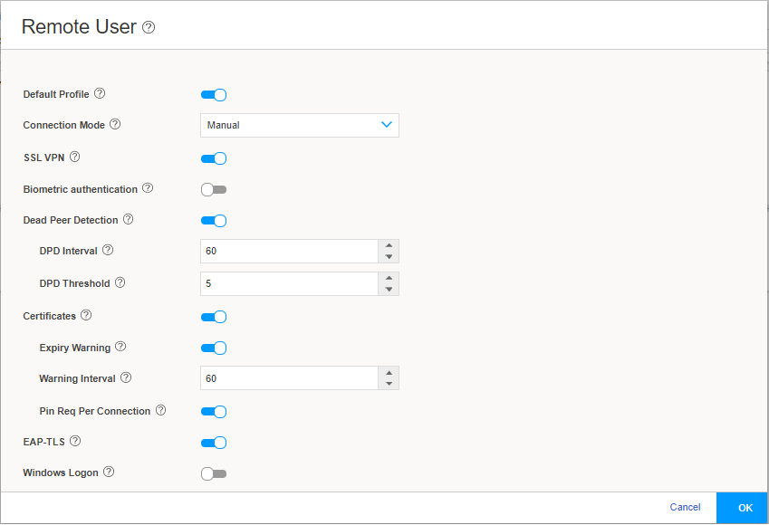
Figure 8 shows an example of the Remote User page.
Configure the remote user client by selecting the options on the Remote User page and then clicking OK :
Table 1 summarizes the remote user settings options.
Table 1: Remote User Client Settings Options Remote User Client Settings
Description
Default Profile
The Default Profile is enabled by default. If you do not want this profile to be the default profile, click the toggle button.
If you enable Default Profile for the VPN connection profile, Juniper Secure Connect automatically selects default profile as realm name (in this example: https://12.12.12.12/). In this case, it is optional to enter the realm name in Juniper Secure Connect.
If you disable Default Profile for the VPN connection profile, you must enter the realm name along with the gateway address (in this example: https://12.12.12.12/JUNIPER_SECURE_CONNECT) in Juniper Secure Connect.
Note:Starting in Junos OS 23.1R1 Release, default profile is deprecated in J-Web. However, in CLI—rather than immediately removing it—we provide backward compatibility and a chance to make your existing configuration conform to the changed configuration. You’ll receive a warning message if you continue to use the default-profile option in your configuration. However existing deployments are not affected if you modify the current configuration using CLI. See default-profile (Juniper Secure
Connection Mode
To establish the client connection manually or automatically, select the appropriate option.
If you select Manual, then in the Juniper Secure Connect application, to establish a connection, you must either click the toggle button or select Connection > Connect from the menu.
If you select Always, then Juniper Secure Connect automatically establishes the connection.
Known Limitation:
Android device: If you use or select Always, then the configuration is downloaded from the first used SRX device. If the first SRX Series Firewall configuration changes or if you connect to a new SRX device, the configuration does not get downloaded to the Juniper Secure Connect application.
This means that once you connect in the Always mode using the Android device, any configuration changes in the SRX Series Firewall do not take effect on Juniper Secure Connect.
SSL VPN
To enable support for SSL VPN connection from the Juniper Secure Connect application to the SRX Series Firewalls, click the toggle button. By enabling SSL VPN, the client has the flexibility in connecting the SRX Series Firewalls. By default, SSL VPN is enabled.
Biometric authentication
This option is disabled by default. If you enable this option, when you click connect in Juniper Secure Connect, Juniper Secure Connect displays an authentication prompt.
This option allows the user to protect their credentials using the operating system’s built-in biometric authentication support.
Dead Peer Detection
Dead Peer Detection (DPD) is enabled by default to allow the client to detect if the SRX Series Firewall is not reachable, disable the connection till reachability is restored.
Certificates
This option is enabled by default to configure certificate options.
Expiry Warning—This option is enabled by default. When enabled, you receive certificate expiration warning on the Secure Connect client, when the certificate is about to expire.
Warning Interval—Enter the Interval at which the warning is displayed in days
Pin Req Per Connection—This option is enabled by default. When enabled, you must enter the certificate pin for every connection.
EAP-TLS
EAP-TLS is enabled by default.
Windows Logon
This option allows users to logon to the local Windows system through an already established VPN tunnel (using Windows Pre-Logon), so that it is authenticated to the central Windows domain or Active Directory.
- Click Local Gateway to configure the Local
Gateway settings.
Figure 9 shows an example of the local gateway configuration settings.
Figure 9: Local Gateway Configuration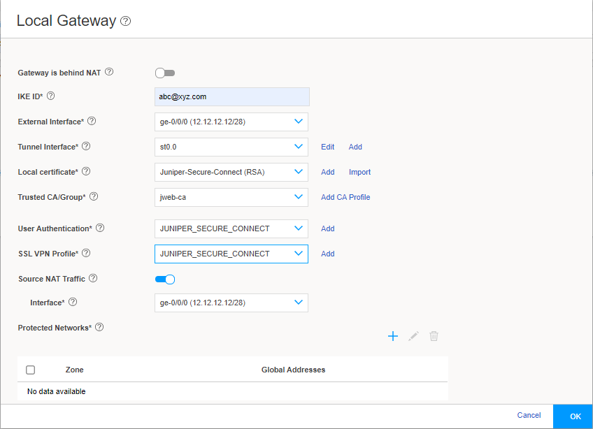
If you enable Gateway is behind NAT, a text box appears. In the text box, enter the NAT IP address. We support only IPv4 addresses. NAT address is the external address.
-
Enter a IKE ID in user@hostname.com format. For example, abc@xyz.com.
-
In the External Interface field, select the IP address for the clients to connect. You must enter this same IP address (in this example: https://12.12.12.12/) for the Gateway Address field in the Juniper Secure Connect application.
If you enable Gateway is behind NAT, then the NAT IP address becomes the gateway address.
From the Tunnel Interface drop-down list, select an interface to bind it to the route-based VPN. Alternatively click Add. If you click Add, the Create Tunnel Interface page appears.
Figure 10 shows an example of the Create Tunnel Interface page.
Figure 10: Create Tunnel Interface Page
The next available ST0 logical interface number is displayed in the Interface Unit field and you can enter a description for this interface. Select the zone to add this tunnel interface to. If Auto-create Firewall Policy (in Create Remote Access page) is set to Yes, the firewall policy uses this zone. Click OK.
From the Local certificate field, select one of your already externally signed local certificates. Click Add to add a new local certificate or click Import to import the local certificate.
Figure 11 shows a configuration example only.
Figure 11: Generate Certificate Page For Local certificate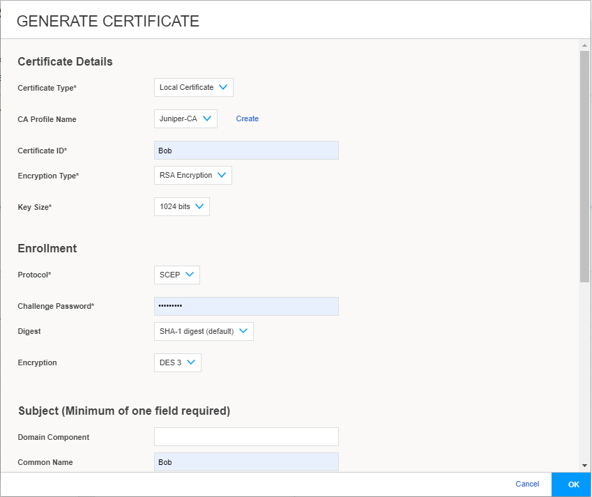
For CA certificate, from the Trusted CA/Group field, select one of your already externally signed CA certificates, including the matching Trusted CA/Group. If you do not have any of these, click Add CA Profile and fill in the values that match your environment. Figure 12 shows an example of Add CA PROFILE page.
Figure 12: ADD CA PROFILE page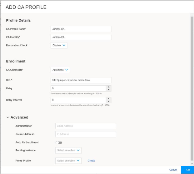
In the User Authentication dropdown menu, you can select existing access profile or click Add to create a new Access Profile. If you click Add, the Create Access Profile window appears.
Figure 13 shows an example of the Create Access Profile page.
Figure 13: Create Access Profile Page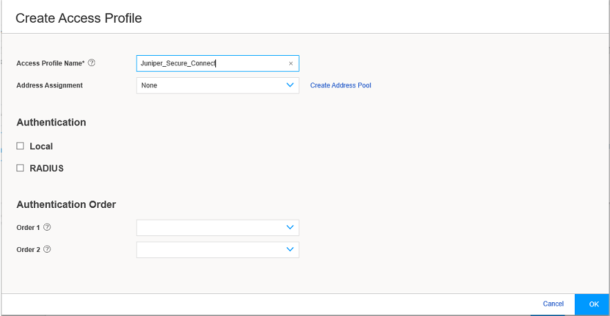
Enter the access profile name. From the Address Assignment drop-down list, select an address pool or click Create Address Pool. If you click Create Address Pool, the Create Address Pool page appears.
Figure 14 shows an example of the Create Address Pool page.
Figure 14: Create Address Pool Page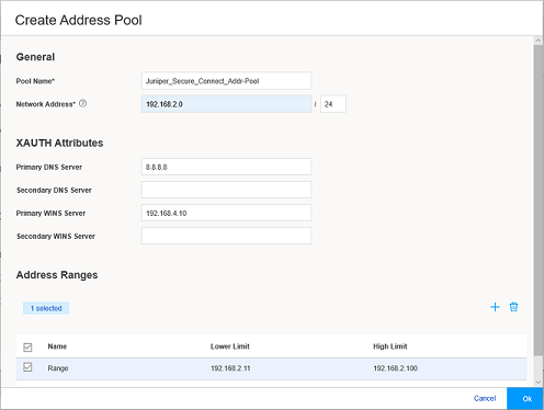
Enter the details for the Local IP pool that is in the VPN policy for the clients. Enter a name for the IP address pool.
Enter the network address that you use for the address assignment.
Enter your DNS server address. Enter WINS server details, if required. Now click the add icon (+) to create the address range to assign IP addresses to the clients.
Enter the name, and the lower and higher limits. After entering the details, click OK.
Select the RADIUS check box, where all the authentication details are stored on an external radius server.
Click on the add icon (+) to configure the radius server details. See Figure 15.
Figure 15: Create RADIUS Server Page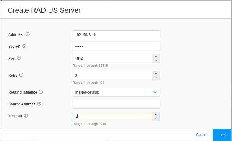
Enter the Radius Server IP Address, the Radius Secret, and Source Address for the radius communications to be sourced from. Click OK.
In the Authentication Order, from Order 1 drop-down list select RADIUS. Click OK to complete the access profile configuration.
Figure 16 shows an example of Create Access Profile page.
Figure 16: Create Access Profile Page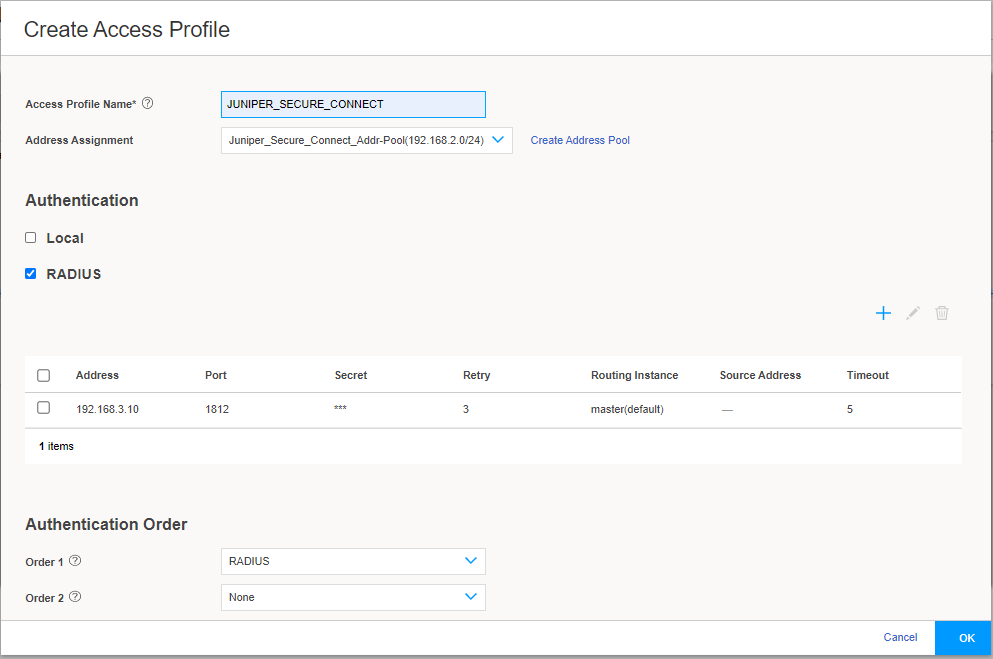
-
From the SSL VPN Profile drop-down list, select an existing profile or click Add to create a new SSL VPN profile. If you click Add, the Add SSL VPN Profile page appears.
Figure 17 shows an example of the Add SSL VPN Profile page.
Figure 17: Add SSL VPN Profile Page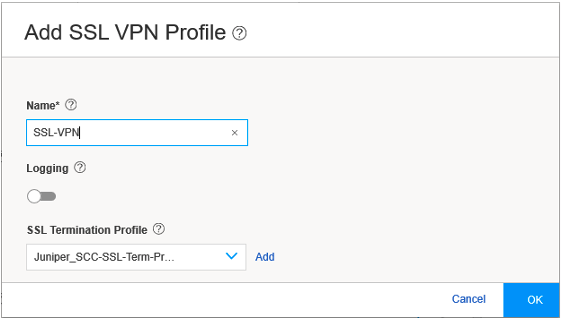
On the Add SSL VPN Profile page , you can configure the SSL VPN profile. Enter the SSL VPN profile name in the Name field, and enable logging using the toggle, if required. In the SSL Termination Profile field, select the SSL termination profile from the drop-down list. SSL termination is a process where the SRX Series Firewalls act as an SSL proxy server, and terminates the SSL session from the client. If you want to create a new SSL termination profile, click Add. The Create SSL Termination Profile page appears.
Figure 18 shows an example of the Create SSL Termination Profile page.
Figure 18: Create SSL Termination Profile Page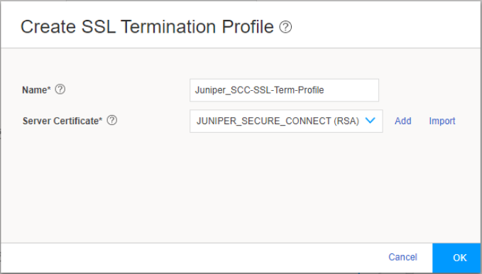
-
Enter the name for the SSL termination profile and select the server certificate that you use for the SSL termination on the SRX Series Firewalls. Click Add to add a new server certificate or click Import to import the server certificate. The server certificate is a local certificate identifier. Server certificates are used to authenticate the identity of a server.
-
Click OK.
-
-
The Source NAT Traffic option is enabled by default. When Source NAT Traffic is enabled, all traffic from the Juniper Secure Connect application is NATed to the selected interface by default. Click the toggle button to disable the Source NAT Traffic option. If the option is disabled, you must ensure that you have a route from your network pointing to the SRX Series Firewalls for handling the return traffic correctly.
Under Protected Networks, click the add icon (+) to select the networks that the Juniper Secure Connect application can connect to.
Figure 19 shows an example of the Create Protected Networks page.
Figure 19: Create Protected Networks Page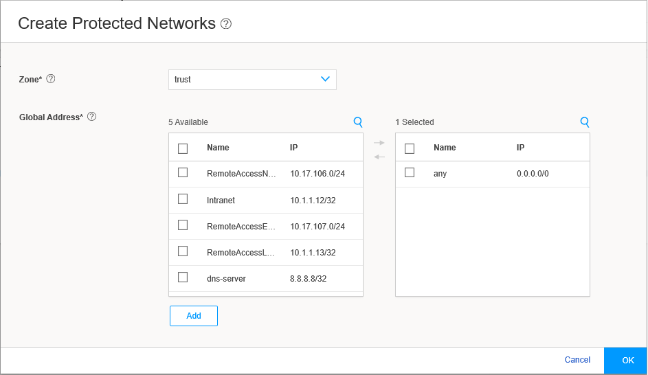
By default, any network 0.0.0.0/0 is allowed. If you configure a specific network, split tunneling for Juniper Secure Connect application is enabled. If you retain the default value, you can restrict access to your defined networks by adjusting the firewall policy from the client network. Click OK, and the selected networks are now in the list of protected networks. Click OK to complete the local gateway configuration.
Figure 20 shows an example of successful completion of remote access configuration with remote user and local gateway.
Figure 20: Complete Remote Access Configuration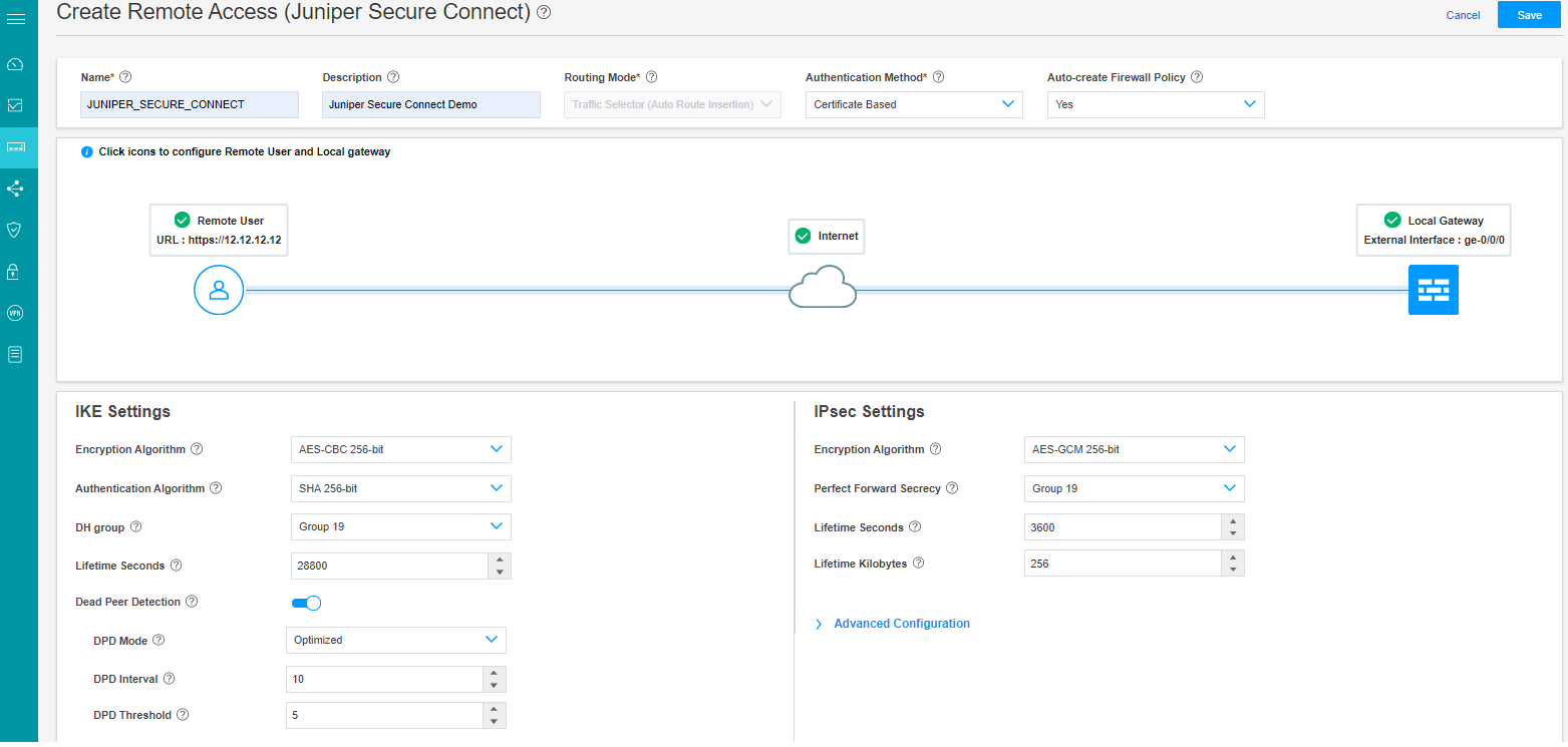
IKE Settings and IPsec Settings are advanced options. J-Web is already configured with default values for the IKE and IPsec parameters. It is not mandatory to configure these settings.
- You can now find the URL for the remote users to connect
to. Copy and store this URL for sharing with your remote users. You
need only the /xxxx information if this configuration is not your
default profile.
Figure 21 highlights the URL that remote user must enter in the Gateway address field in Juniper Secure Connect application to establish remote access connection.
Figure 21: Commit Remote Access Configuration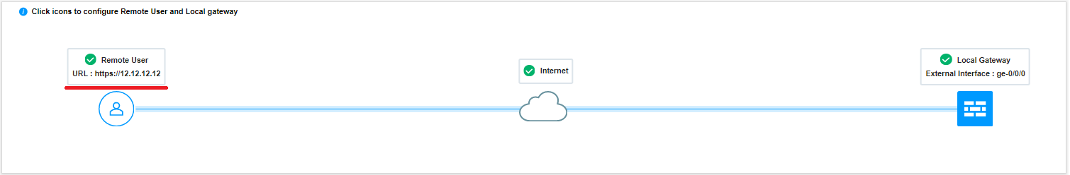
Click Save to complete the Juniper Secure Connect VPN Configuration and associated policy if you have selected the auto policy creation option.
Click the highlighted Commit button (at the top right of the page next to Feedback Button) to commit the configuration.
Download and install Juniper Secure Connect application on the client machine. Launch Juniper Secure Connect and connect to the gateway address of the SRX Series Firewall. You must also place the root CA certificate and user certificate at the appropriate directory location for the respective platform where you’ve installed Juniper Secure Connect application.