Local User Authentication Using Pre-shared Key (CLI Procedure)
Overview
In this configuration, you use the username and password for local user authentication. This configuration option does not allow you to change or recover your credentials without interacting with the firewall administrator, hence we do not recommend this authentication method. Instead, we recommend you to use External User Authentication Using RADIUS method.
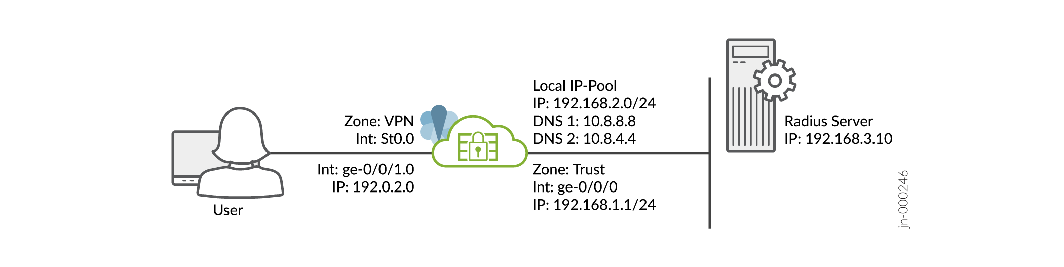
We assume that you have completed the basic setup of your SRX Series devices, including interfaces, zones, and security policies as illustrated in the Figure 1.
For information about prerequisites, see System Requirements.
You must ensure that the SRX Series device uses either a signed certificate or a self-signed certificate instead of the default system-generated certificate. Before you start configuring Juniper Secure Connect, you must bind the certificate to the SRX Series device by executing the following command:
user@host# set system services web-management https pki-local-certificate <cert_name>
For example:
user@host# set system services web-management https pki-local-certificate SRX_Certificate
Where SRX_Certificate is the self-signed certificate.
CLI Quick Configuration
To quickly configure this example on your SRX series devices, copy the following commands, paste them into a text file, remove any line breaks, change any details necessary to match your network configuration, and then copy and paste the commands into the CLI at the [edit] hierarchy level.
[edit]
user@host#

set security ike proposal JUNIPER_SECURE_CONNECT authentication-method pre-shared-keys
set security ike proposal JUNIPER_SECURE_CONNECT dh-group group19
set security ike proposal JUNIPER_SECURE_CONNECT encryption-algorithm aes-256-gcm
set security ike proposal JUNIPER_SECURE_CONNECT lifetime-seconds 28800
set security ike policy JUNIPER_SECURE_CONNECT mode aggressive

set security ike policy JUNIPER_SECURE_CONNECT proposals JUNIPER_SECURE_CONNECT
set security ike policy JUNIPER_SECURE_CONNECT pre-shared-key ascii-text "$9$yYJeMXVwgUjq7-jqmfn6rev"

set security ike gateway JUNIPER_SECURE_CONNECT dynamic hostname ra.example.com
set security ike gateway JUNIPER_SECURE_CONNECT dynamic ike-user-type shared-ike-id
set security ike gateway JUNIPER_SECURE_CONNECT ike-policy JUNIPER_SECURE_CONNECT
set security ike gateway JUNIPER_SECURE_CONNECT dead-peer-detection optimized
set security ike gateway JUNIPER_SECURE_CONNECT dead-peer-detection interval 10
set security ike gateway JUNIPER_SECURE_CONNECT dead-peer-detection threshold 5
set security ike gateway JUNIPER_SECURE_CONNECT version v1-only
set security ike gateway JUNIPER_SECURE_CONNECT aaa access-profile Juniper_Secure_Connect
set security ike gateway JUNIPER_SECURE_CONNECT tcp-encap-profile SSL-VPN
set security ike gateway JUNIPER_SECURE_CONNECT external-interface ge-0/0/1


set security ipsec proposal JUNIPER_SECURE_CONNECT encryption-algorithm aes-256-gcm
set security ipsec proposal JUNIPER_SECURE_CONNECT lifetime-seconds 3600
set security ipsec policy JUNIPER_SECURE_CONNECT perfect-forward-secrecy keys group19
set security ipsec policy JUNIPER_SECURE_CONNECT proposals JUNIPER_SECURE_CONNECT

set security ipsec vpn JUNIPER_SECURE_CONNECT bind-interface st0.0
set security ipsec vpn JUNIPER_SECURE_CONNECT ike gateway JUNIPER_SECURE_CONNECT
set security ipsec vpn JUNIPER_SECURE_CONNECT ike ipsec-policy JUNIPER_SECURE_CONNECT
set security ipsec vpn JUNIPER_SECURE_CONNECT traffic-selector ts-1 local-ip 0.0.0.0/0
set security ipsec vpn JUNIPER_SECURE_CONNECT traffic-selector ts-1 remote-ip 0.0.0.0/0
set security remote-access profile ra.example.com ipsec-vpn JUNIPER_SECURE_CONNECT
set security remote-access profile ra.example.com access-profile Juniper_Secure_Connect
set security remote-access profile ra.example.com client-config JUNIPER_SECURE_CONNECT
set security remote-access client-config JUNIPER_SECURE_CONNECT connection-mode manual
set security remote-access client-config JUNIPER_SECURE_CONNECT dead-peer-detection interval 60
set security remote-access client-config JUNIPER_SECURE_CONNECT dead-peer-detection threshold 5
set security remote-access default-profile ra.example.com


set access address-assignment pool Juniper_Secure_Connect_Addr-Pool family inet network 192.168.2.0/24
set access address-assignment pool Juniper_Secure_Connect_Addr-Pool family inet range Range low 192.168.2.11
set access address-assignment pool Juniper_Secure_Connect_Addr-Pool family inet range Range high 192.168.2.100
set access address-assignment pool Juniper_Secure_Connect_Addr-Pool family inet xauth-attributes primary-dns 10.8.8.8/32
set access address-assignment pool Juniper_Secure_Connect_Addr-Pool family inet xauth-attributes primary-wins 192.168.4.10/32
set access profile Juniper_Secure_Connect address-assignment pool Juniper_Secure_Connect_Addr-Pool
set access firewall-authentication web-authentication default-profile Juniper_Secure_Connect
set access profile Juniper_Secure_Connect client Bob firewall-user password "$9$abGjqTz6uORmfORhSMWJGD"

set services ssl termination profile Juniper_SCC-SSL-Term-Profile server-certificate JUNIPER_SECURE_CONNECT(RSA)
set security tcp-encap profile SSL-VPN ssl-profile Juniper_SCC-SSL-Term-Profile
set security policies from-zone trust to-zone VPN policy JUNIPER_SECURE_CONNECT-1 match source-address any
set security policies from-zone trust to-zone VPN policy JUNIPER_SECURE_CONNECT-1 match destination-address any
set security policies from-zone trust to-zone VPN policy JUNIPER_SECURE_CONNECT-1 match application any
set security policies from-zone trust to-zone VPN policy JUNIPER_SECURE_CONNECT-1 then permit
set security policies from-zone trust to-zone VPN policy JUNIPER_SECURE_CONNECT-1 then log session-close
set security policies from-zone VPN to-zone trust policy JUNIPER_SECURE_CONNECT-2 match source-address any
set security policies from-zone VPN to-zone trust policy JUNIPER_SECURE_CONNECT-2 match destination-address any
set security policies from-zone VPN to-zone trust policy JUNIPER_SECURE_CONNECT-2 match application any
set security policies from-zone VPN to-zone trust policy JUNIPER_SECURE_CONNECT-2 then permit
set security policies from-zone VPN to-zone trust policy JUNIPER_SECURE_CONNECT-2 then log session-close

set interfaces ge-0/0/0 unit 0 family inet address 192.0.2.0/24
set interfaces ge-0/0/1 unit 0 family inet address 198.51.100.0/24
set interfaces st0 unit 0 family inet

set security zones security-zone trust host-inbound-traffic system-services all
set security zones security-zone trust host-inbound-traffic protocols all
set security zones security-zone trust interfaces ge-0/0/0.0
set security zones security-zone vpn host-inbound-traffic system-services all
set security zones security-zone vpn host-inbound-traffic protocols all
set security zones security-zone VPN interface st0.0
set security zones security-zone vpn interfaces ge-0/0/1.0
Step-by-Step-Procedure
To configure VPN settings using the command line interface:
From operational mode, confirm your configuration by
entering the show security, show access, and show
services commands. If the output does not display the intended configuration,
repeat the configuration instructions in this example to correct it.
[edit]
user@host> show security
   ike {
       proposal JUNIPER_SECURE_CONNECT {

           authentication-method pre-shared-keys;
           dh-group group19;
           encryption-algorithm aes-256-gcm;
           lifetime-seconds 28800;
       }
       policy JUNIPER_SECURE_CONNECT {
           mode aggressive;
;
           proposals JUNIPER_SECURE_CONNECT;
           pre-shared-key ascii-text "$9$lifv87wYojHm-VHmfT/9evW"; ## SECRET-DATA
       }
       gateway JUNIPER_SECURE_CONNECT {
           ike-policy JUNIPER_SECURE_CONNECT;
           dynamic {
               hostname ra.example.com;
               ike-user-type shared-ike-id;
           }
           dead-peer-detection {
               optimized;
               interval 10;
               threshold 5;
           }
           external-interface ge-0/0/1;

           aaa {
               access-profile Juniper_Secure_Connect;
           }
           version v1-only;
           tcp-encap-profile SSL-VPN;
       }
   }
   ipsec {
       proposal JUNIPER_SECURE_CONNECT {

           encryption-algorithm aes-256-gcm;
           lifetime-seconds 3600;
       }
       policy JUNIPER_SECURE_CONNECT {

           perfect-forward-secrecy {
               keys group19;
           }
           proposals JUNIPER_SECURE_CONNECT;
       }
       vpn JUNIPER_SECURE_CONNECT {
           bind-interface st0.0;

           ike {
               gateway JUNIPER_SECURE_CONNECT;
               ipsec-policy JUNIPER_SECURE_CONNECT;
           }
           traffic-selector ts-1 {
               local-ip 0.0.0.0/0;
               remote-ip 0.0.0.0/0;
           }
       }
   }
   remote-access {
       profile ra.example.com {
           ipsec-vpn JUNIPER_SECURE_CONNECT;
           access-profile Juniper_Secure_Connect;
           client-config JUNIPER_SECURE_CONNECT;
       }
       client-config JUNIPER_SECURE_CONNECT {
           connection-mode manual;
           dead-peer-detection {
               interval 60;
               threshold 5;
           }
       }
       default-profile ra.example.com;
   }
   policies {
       from-zone trust to-zone VPN {
           policy JUNIPER_SECURE_CONNECT-1 {
               match {
                   source-address any;
                   destination-address any;
                   application any;
               }
               then {
                   permit;
                   log {
                       session-close;
                   }
               }
           }
       }
       from-zone VPN to-zone trust {
           policy JUNIPER_SECURE_CONNECT-2 {
               match {
                   source-address any;
                   destination-address any;
                   application any;
               }
               then {
                   permit;
                   log {
                       session-close;
                   }
               }
           }
       }
   }
   tcp-encap {
       profile SSL-VPN {
           ssl-profile Juniper_SCC-SSL-Term-Profile;
       }
   }
[edit]
user@host> show access
  access {
      profile Juniper_Secure_Connect {
          client Bob {
              firewall-user {
                  password "$9$m5z6p0IreW9AeWLxwsP5Q"; ## SECRET-DATA
              }
          }
          address-assignment {
              pool Juniper_Secure_Connect_Addr-Pool;
          }
      }
      address-assignment {
          pool Juniper_Secure_Connect_Addr-Pool {
              family inet {
                  network 192.168.2.0/24;
                  range Range {
                      low 192.168.2.11;
                      high 192.168.2.100;
                  }
                  xauth-attributes {
                      primary-dns 10.8.8.8/32;
                      primary-wins 192.168.4.10/32;
                  }
              }
          }
      }
      firewall-authentication {
          web-authentication {
              default-profile Juniper_Secure_Connect;
          }
      }
  }
[edit]
user@host> show services
   ssl {
       termination {
           profile Juniper_SCC-SSL-Term-Profile {
               server-certificate JUNIPER_SECURE_CONNECT(RSA);
           }
       }
   }
Make sure that you already have a server certificate to attach with the SSL termination profile.
[edit]
user@host> show interfaces
ge-0/0/0 {
    unit 0 {
        family inet {
            address 192.0.2.0/24;
        }
    }
}
ge-0/0/1 {
    unit 0 {
        family inet {
            address 198.51.100.0/24;
        }
    }
}
st0 {
    unit 1 {
        family inet;
    }
}
[edit]
user@host> show security zones
security-zone trust {
    host-inbound-traffic {
        system-services {
            all;
        }
        protocols {
            all;
        }
    }
    interfaces {
        ge-0/0/0.0;
    }
}
security-zone vpn {
    host-inbound-traffic {
        system-services {
            all;
        }
        protocols {
            all;
        }
    }
    interfaces {
        st0.1;
        ge-0/0/1.0;
    }
}
When you are done configuring the feature on your device, enter commit from configuration mode.