
ON THIS PAGE
Data Center Edge Firewall Use Case
Learn how to deploy the SRX1600, SRX4120, or SRX4300 Firewalls at the data center edge to shield ingress-facing applications and services from internet-borne attacks. Configure layered controls and attack-specific policies to block threats effectively and reliably. Integrate with HPE Networking ATP Cloud service to use automated intelligence that quickly identifies and mitigates threats across your environment.
Overview
The SRX1600, SRX4120, and SRX4300 Firewalls are designed to secure data center perimeters by providing protection through advanced features. Data centers require an ingress point for clients to access services, making the perimeter a critical area to secure. As a data center edge firewall, these firewalls protect applications by controlling server access and ensure that the critical applications remain secure and operational.
Use your firewall to effectively block attacks targeting data center services. These firewalls provide high-performance firewall functions, including Screens, intrusion prevention system (IPS), and Security Intelligence (SecIntel).
For more details see, Data Center Next-Generation Firewall Use Case—Juniper Validated Design (JVD).
Benefits
-
Enhance data center security by controlling incoming and outgoing network traffic to prevent unauthorized access and potential breaches.
-
Detect and mitigate advanced threats using server-side IPS to identify and address vulnerabilities promptly.
-
Use real-time threat intelligence against emerging security threats to enable proactive protection and reduce the risk of successful attacks.
-
Ensure high availability and minimal downtime through redundancy and failover to maintain continuous operation and reliability of critical services.
-
Provide protection for high-transaction workloads to make it suitable for sectors with stringent security requirements, such as financial services and cloud providers.
Topology
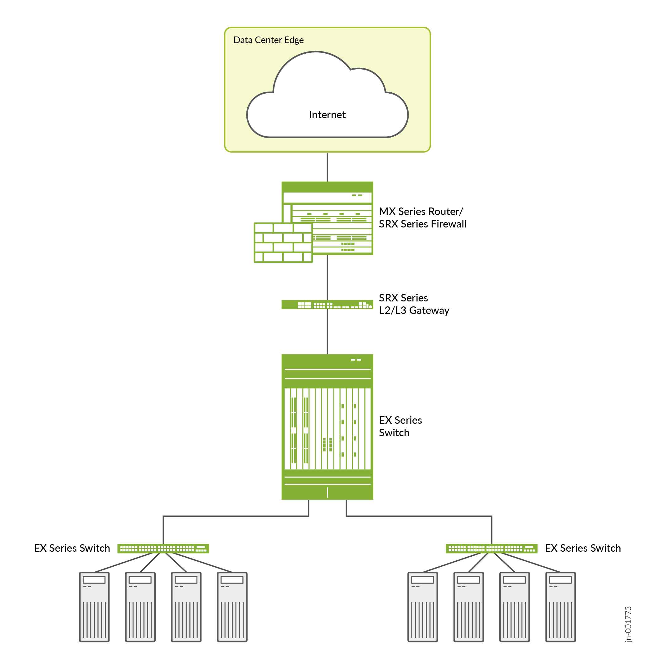
Deploy the SRX1600, SRX4120, or SRX4300 Firewall as a data center edge firewall in segments such as financial services, SaaS providers, Web 2.0, and cloud providers for security features such as firewall, server-side IPS, high availability, and threat intelligence.
-
Each physical port is assigned a role that defines the firewall's position in the topology to separate external, internal, and DMZ networks.
-
WAN interface—Connect to the router facing the Internet.
-
LAN interface—Connect to the L2 or L3 Gateway and ultimately to the data center fabric.
-
DMZ interfaces (optional)—Host public‑facing servers outside the trusted LAN.
-
We support Multinode High Availability (MNHA) in active/backup mode and in active/active mode with support of multiple services redundancy groups (SRGs). For the complete list of supported features and platforms, see Multinode High Availability in Feature Explorer.
| Diagram Block | Firewall Configuration Section | Purpose |
|---|---|---|
|
Router → Firewall |
Interfaces, Untrust Zone, Routing |
Defines WAN connectivity and default route |
|
Firewall |
Zones, Policies, NAT |
Controls all traffic between the Internet and the data center |
|
Firewall → L2 or L3 Gateway |
Interfaces, Trust Zone |
Secures connection to the internal data center network |
|
Switching and Servers |
Policies, NAT, Logging |
Manages how internal workloads connect externally |
Baseline Configurations
The baseline configurations in this topic provide a foundational template that helps standardize deployments, improve operational reliability, and accelerate secure onboarding of the SRX1600, SRX4120, and SRX4300 Firewalls in a data center edge architecture.
- Stateful Firewall
- Security Zones and Policies
- NAT
- Advanced Layer 7 Security Features
- Multinode High Availability (MNHA)
- CGNAT for MNHA
- Zero Trust Security
Stateful Firewall
Stateful firewall configuration on these firewalls involves defining security zones, policies, and enabling flow-based processing. Here's a foundational CLI example for a data center edge setup with trust and untrust zones:
# Enable chassis cluster
set chassis cluster reth-count 2

set interfaces reth0 redundant-ether-options redundancy-group 1
set interfaces reth0 redundant-ether-options minimum-links 1
set interfaces ge-0/1/0 gigether-options redundant-parent reth0
set interfaces ge-0/1/3 gigether-options redundant-parent reth0
set interfaces reth0 unit 0 family inet address 192.168.16.18/24  # Trust-facing

set interfaces reth1 redundant-ether-options redundancy-group 1
set interfaces reth1 redundant-ether-options minimum-links 1
set interfaces et-0/3/0 gigether-options redundant-parent reth1  # Node 0
set interfaces et-0/3/1 gigether-options redundant-parent reth1  # Node 1 (backup)
set interfaces reth1 unit 0 family inet address 203.0.113.233/24  # Untrust-facing

set security zones security-zone trust interfaces reth0.0
set security zones security-zone untrust interfaces reth1.0

# Global policy to permit necessary traffic (stateful by default)
set security policies from-zone trust to-zone untrust policy allow-data match source-address any
set security policies from-zone trust to-zone untrust policy allow-data match destination-address any
set security policies from-zone trust to-zone untrust policy allow-data match application any
set security policies from-zone trust to-zone untrust policy allow-data then permit

# Commit and enable flow-based processing (default on SRX1600, SRX4120, and SRX4300 Firewalls)
commit
Security Zones and Policies
The SRX1600, SRX4120, and SRX4300 Firewalls ship with a factory-default configuration that includes two security zones (trust and untrust), a default outbound permit policy from trust to untrust, and source NAT configured on the trust zone.
Security Zone
Security zones are the foundation of policy configuration. Security zones logically group interfaces based on trust level. All security policies in Junos OS are zone-based. You must assign traffic to zones before the policy can permit or deny it.
You can configure up to 8000 interfaces within a security zone. Define zones for your data center edge deployment (for example, internal, external, and DMZ zones).
Define what traffic is allowed between zones.
-
trust to → untrust–Allows data center servers or users to reach the Internet.
-
untrust to DMZ–Permits selective inbound traffic to public services (example: HTTP).
-
Default Deny–Blocks all other interzone traffic not explicitly allowed.
You can configure security zones:
set security zones security-zone untrust interfaces ge-0/1/0
set security zones security-zone untrust host-inbound-traffic system-services ping
set security zones security-zone untrust host-inbound-traffic system-services ike
set security zones security-zone trust interfaces ge-0/1/3
set security zones security-zone trust host-inbound-traffic system-services ping
set security zones security-zone trust host-inbound-traffic system-services ssh
Define Security Policies Between Zones
-
You configure security policies in a from-zone to to-zone direction. Each policy contains:
- A policy name
- Match criteria (source address, destination address, application)
- Actions (permit or deny)
To allow traffic between zones, configure directional policies:
set security policies from-zone trust to-zone untrust policy permit-outbound match source-address any
set security policies from-zone trust to-zone untrust policy permit-outbound match destination-address any
set security policies from-zone trust to-zone untrust policy permit-outbound match application any
set security policies from-zone trust to-zone untrust policy permit-outbound then permit

set security policies from-zone untrust to-zone trust policy deny-inbound match source-address any
set security policies from-zone untrust to-zone trust policy deny-inbound match destination-address any
set security policies from-zone untrust to-zone trust policy deny-inbound match application any
set security policies from-zone untrust to-zone trust policy deny-inbound then deny
-
Configure bidirectional traffic flow: To allow traffic in both directions, you must configure separate policies for each direction. For example, configure a
deny-allpolicy from untrust to trust if inbound traffic should be restricted. -
Verify your configuration using the
show security zonesand theshow security policiescommands.
For more information, see Configuring Security Policies.
NAT
Source NAT allows internal servers (192.168.1.0/24) to access the Internet using the firewall’s public IP address. Use destination NAT when you want to expose internal or DMZ-hosted servers to the Internet (for example, a webserver).
- Use the firewall between private data center networks and the router.
- NAT ensures private IP addresses remain hidden and routable only internally.
Source NAT Configuration
set interfaces ge-0/1/0 unit 0 family inet address <IP address> # Untrust example
set security nat source rule-set trust-to-untrust from zone trust
set security nat source rule-set trust-to-untrust to zone untrust
set security nat source rule-set trust-to-untrust rule nat-rule match source-address 192.168.1.0/24
set security nat source rule-set trust-to-untrust rule nat-rule then source-nat interface
set security policies from-zone trust to-zone untrust policy allow-out match source-address any
set security policies from-zone trust to-zone untrust policy allow-out match destination-address any
set security policies from-zone trust to-zone untrust policy allow-out match application any
set security policies from-zone trust to-zone untrust policy allow-out then permit
Verify your configurations using the commit check command, then the
show security nat source summary command, and then the show
security flow session command.
For destination and static NAT, add rules accordingly, see Network Address Translation User Guide.
Advanced Layer 7 Security Features
-
IDP or IPS—The intrusion prevention system (IPS) on the SRX1600, SRX4120, and SRX4300 Firewalls, which is part of Junos OS security services, detects and prevents network attacks by inspecting traffic against signature databases, anomaly detection, and custom rules. Enable IPS in the security policy and then in actions. The configuration supports Layer 7 signature updates.
-
IDP security packages require dedicated security commands, not the general
request system software addwhich is for Junos OS, firmware, or other system packages.-
Download—Use the
request security idp security-package
                        download
command to download the package. -
Install—Use the
request security idp security-package
                        install
command to install it. -
Verify—Use the
request security idp security-package install
                        status
command to verify the installation status.
-
-
Configure IDP policy (create a basic rulebase).
set security idp idp-policy my-ips-policy rulebase-ips rule 1 match from-zone trust
set security idp idp-policy my-ips-policy rulebase-ips rule 1 match to-zone untrust
set security idp idp-policy my-ips-policy rulebase-ips rule 1 match source-address any
set security idp idp-policy my-ips-policy rulebase-ips rule 1 match destination-address any
set security idp idp-policy my-ips-policy rulebase-ips rule 1 match application any
set security idp idp-policy my-ips-policy rulebase-ips rule 1 match attacks predefined-attacks ALL
set security idp idp-policy my-ips-policy rulebase-ips rule 1 then action drop-packet
set security idp idp-policy my-ips-policy

set security policies from-zone trust to-zone untrust policy ips-policy match source-address any
set security policies from-zone trust to-zone untrust policy ips-policy match destination-address any
set security policies from-zone trust to-zone untrust policy ips-policy match application any
set security policies from-zone trust to-zone untrust policy ips-policy then permit application-services idp
-
To configure
match attacks predefined-attacksin an IDP policy on your firewall, use thepredefined-attacksandpredefined-attack-groupsstatements under the rulebase-ips match conditions.Basic Configuration Syntax
[edit security idp]
set idp-policy <policy-name> rulebase-ips rule <rule-number> match attacks predefined-attacks "<attack-name>"
set idp-policy <policy-name> rulebase-ips rule <rule-number> match attacks predefined-attack-groups "<group-name>"
Example: Matching Specific Predefined Attacks
[edit security idp]
set idp-policy idpengine rulebase-ips rule 1 match attacks predefined-attacks "FTP:USER:ROOT"
set idp-policy idpengine rulebase-ips rule 1 match attacks predefined-attack-groups "HTTP - All"
set idp-policy idpengine rulebase-ips rule 1 then action drop-packet log-session-init
-
Predefined attacks are included in the IDP signature database, which is regularly updated with new attack signatures and threat patterns.
-
Use ordered match for compound attacks requiring specific sequence.
-
Activate the policy after configuration using the
set security idp
                        active-policy <policy-name>
command. -
View available predefined attack signatures or groups using the
[edit
                        security idp idp-policy]
command. -
Requires IDP license and signature package installation
-
-
Commit and verify the configurations:
show security idp status
show security idp security-package
show security policies
-
-
HPE Networking ATP Cloud/ICAP: HPE Networking ATP Cloud integrates with SRX1600, SRX4120, and SRX4300 Firewalls to provide advanced malware detection and threat analysis at the data center edge. Use the HPE Networking ATP Cloud op script for automated enrollment, certificates, and connection setup.
Prerequisites
- Internet access from Routing Engine (control plane) and Packet Forwarding Engine (data plane).
- Licenses for HPE Networking ATP Cloud using HPE Networking Security Director or the Junos OS CLI.
- Onboard your firewall using HPE Networking Security Director Cloud or SZTP for simplified setup.
Certificates and SSL profiles:
set services ssl initiation profile aamw-ssl trusted-ca-certificate aamw-secintel-ca
set services ssl initiation profile aamw-ssl client-certificate aamw-srx-cert
set services advanced-anti-malware connection authentication tls-profile aamw-ssl
set services security-intelligence authentication tls-profile aamw-ssl
Advanced anti-malware (AAMW) policy:
set services advanced-anti-malware policy default-profile connection-security-profile aamw-ssl
# Reference in security policy:
set security policies from-zone trust to-zone untrust policy allow-selected then permit application-services advanced-anti-malware-policy default-profile
HPE Networking Security Director Cloud integration: Enroll devices automatically and manage HPE Networking ATP Cloud settings through the portal (CLI not required post-enrollment).
- SSL proxy (Layer 7 decryption): For encrypted traffic inspection, use:
SSL Proxy Profile Configuration:
set services ssl proxy profile <profile-name> root-ca <ca-profile>
set services ssl proxy profile <profile-name> local-certificate <cert-id>
set services ssl proxy profile <profile-name> actions configure  # For forward proxy
Apply to security policies:
set security policies from-zone trust to-zone untrust policy <policy> then permit application-services ssl-proxy profile-name <profile>
For more information, see Juniper ATP Cloud Administrator Guide.
Multinode High Availability (MNHA)
Deploy dual SRX1600, SRX4120, or SRX4300 Firewalls with MNHA to ensure:
-
High availability through failover
-
Redundant control and data planes
-
Continuous traffic flows during maintenance activities or device failures
Data center edge redundancy is critical because a firewall failure must not disrupt business operations.
Configure MNHA on both nodes. Use configuration groups for scalability if needed.
Enable configuration synchronization for shared MNHA configuration using Junos configuration groups:
set system commit peer-synchronize  # Enables auto-sync on commit to peers
set system commit peers <peer-name> user <username> authentication <password-or-key>  # Define peers (e.g., peer-name=ad2, username=root)
set system static-host-mapping inet <peer-hostname> <peer-ip>  # Host mapping for peer resolution (e.g., ad2 192.168.255.41)
set system services netconf ssh  # Enables NETCONF/SSH for secure peer sync
commit synchronize  # Initial sync; subsequent commits auto-sync
Verify your configuration using the following commands:
show system commit: Check sync status and history.show system commit peers: List configured peers.show | compare: View pending changes before sync.
Services Redundancy Groups (SRGs) are failover units in MNHA to manage security services. The services include IPsec VPN, NAT, and firewall policies in active/active (SRG0) or active/backup (SRG1+) modes. SRG0 provides stateful synchronization for L4 through L7 services (excluding IPsec VPN) in active/active mode. SRG1+ manages IPsec and virtual IPs with monitoring and failover options. Configure SRGs using a basic L3 MNHA example:
Configure either node in a dual SRX1600, SRX4120, or SRX4300 Firewall deployment after enabling MNHA. Use configuration groups to synchronize settings between nodes, and apply changes using the
commit peersandcommit synchronizecommands.- SRG1 (data plane services, active/active with signal
routes):
set chassis high-availability services-redundancy-group 1 active/backup-signal-route <route-prefix>
set chassis high-availability services-redundancy-group 1 deployment-type layer3
set chassis high-availability services-redundancy-group 1 activeness-priority 100  # Higher = preferred active
set chassis high-availability services-redundancy-group 1 virtual-ip <VIP/index>  # For L2 default gateway
set chassis high-availability services-redundancy-group 1 preemption
set chassis high-availability services-redundancy-group 1 activeness-probe
set chassis high-availability services-redundancy-group 1 process-packet-on-backup
- SRG0 (control plane,
active/backup):
set chassis high-availability services-redundancy-group 0 peer-id 2 # Peer-id 1 on another node
set chassis high-availability redundancy-group 0 shutdown-on-failure
set chassis high-availability redundancy-group 0 install-on-failure-route <route>
Integrate with zones, policies, NAT, and IPsec:
- Assign interfaces and security zones.
- Apply identical security policies, NAT rules, and IPsec configurations on both nodes.
- Allow IKE/SSH on ICL zone for encryption/sync.
In L3 (Route Mode) deployments, use active/backup signal routes (
install-on-failure-route) and optional BGP/static routes to direct traffic toward the active node.Create a dedicated virtual router for signal routes. Active/backup signal routes are used in L3 (Route Mode) deployments to indicate node availability and influence routing decisions. These routes do not require virtual IP addresses unless the deployment uses Hybrid Mode.
set routing-instances MNHA-signal-routes instance-type virtual-router
Interfaces and zones (example for ICL and revenue ports): Assign revenue interfaces to security zones. For interchassis links (ICL), use Gigabit Ethernet (GbE) ports in a routing instance for segmentation.
set security zones security-zone icl interfaces xe-0/0/0.0 host-inbound-traffic system-services ssh
set security zones security-zone icl interfaces xe-0/0/0.0 host-inbound-traffic system-services high-availability
set security zones security-zone icl interfaces xe-0/0/0.0 host-inbound-traffic system-services ike
set security zones security-zone icl interfaces xe-0/0/0.0 host-inbound-traffic protocols bfd
Note: The SRX1600 Firewall does not support the xe-0/0/0 interface.- Monitoring and failover options (SRG1) include; Activeness probing, BFD, and
IP/interface
monitoring:
set chassis high-availability services-redundancy-group 1 activeness-probe dest-ip <peer-ip> src-ip <local-ip>
set chassis high-availability services-redundancy-group 1 activeness-probe bfd-liveliness source-ip <local> destination-ip <peer> interface <if>
- Verify and
commit:
show chassis high-availability service-redundancy-group 1
show configuration system commit peers # Confirm sync
For more information, see Multinode High Availability.
CGNAT for MNHA
To configure carrier-grade NAT (CGNAT) on your firewall, use the standard Junos OS NAT
configuration hierarchy under [edit security nat]
Create a source NAT Pool:
[edit security nat source]
set pool cgnat-pool address 203.0.113.200/32 to 203.0.113.254/32
set security nat source pool Pool1 port deterministic block-size 10000
Configure source NAT rule set:
[edit security nat source]
set rule-set cgnat-rs from zone trust
set rule-set cgnat-rs to zone untrust
set rule-set cgnat-rs rule cgnat-rule match source-address 192.168.0.0/16
set rule-set cgnat-rs rule cgnat-rule then source-nat pool cgnat-pool
Create security policies:
[edit security policies]
set from-zone trust to-zone untrust policy allow-cgnat match source-address any
set from-zone trust to-zone untrust policy allow-cgnat match destination-address any
set from-zone trust to-zone untrust policy allow-cgnat match application any
set from-zone trust to-zone untrust policy allow-cgnat then permit
Verify your configuration using the show security nat source rule all,
show security nat source pool, and show services carrier-nat
statistics commands.
Zero Trust Security
The SRX1600, SRX4120, and SRX4300 Firewalls support built-in zero trust capabilities and microsegmentations. Integration with advanced security architectures enables granular policy enforcement and proactive threat prevention across enterprise networks and data centers.
Key features include:
-
Trusted Platform Module (TPM) 2.0 and cryptographically signed IEEE 802.1AR device identification (DevID) for device trust and anti-spoofing.
-
RFC-compliant secure zero-touch provisioning (SZTP) for secure, remote deployment.
-
Wire-speed MACsec on supported interfaces to provide data integrity and confidentiality.
- AI-Predictive Threat Prevention using machine learning for custom signatures, line-rate anti-malware, and protection against known and zero-day threats.
- Integration with HPE Networking ATP Cloud for advanced threat mitigation, including zero-day detection without breaking encryption.
These features enable zero trust by verifying every connection, enforcing policies that follow users, devices, and applications providing network-wide visibility.
For more information, see Juniper Zero Trust Data Center Solution Brief.