
Secure the Control Plane
Learn how to secure the control plane on a Juniper MX204, MX301, MX304, MX10004, or MX10008 router.
On MX Series routers, control-plane protocols run primarily on the Routing Engine CPUs. In modular chassis, certain distributed protocols (for example, BFD and LACP) also run on line card CPUs. Packets destined for router IP addresses—including management-plane traffic and exception traffic—are punted from the Packet Forwarding Engine ASIC to the RE through the host path.
The following diagram compares the host-path implementation in earlier (kernel-based) platforms and the newer Advanced Forwarding Toolkit (AFT) architecture used in current MX platforms.
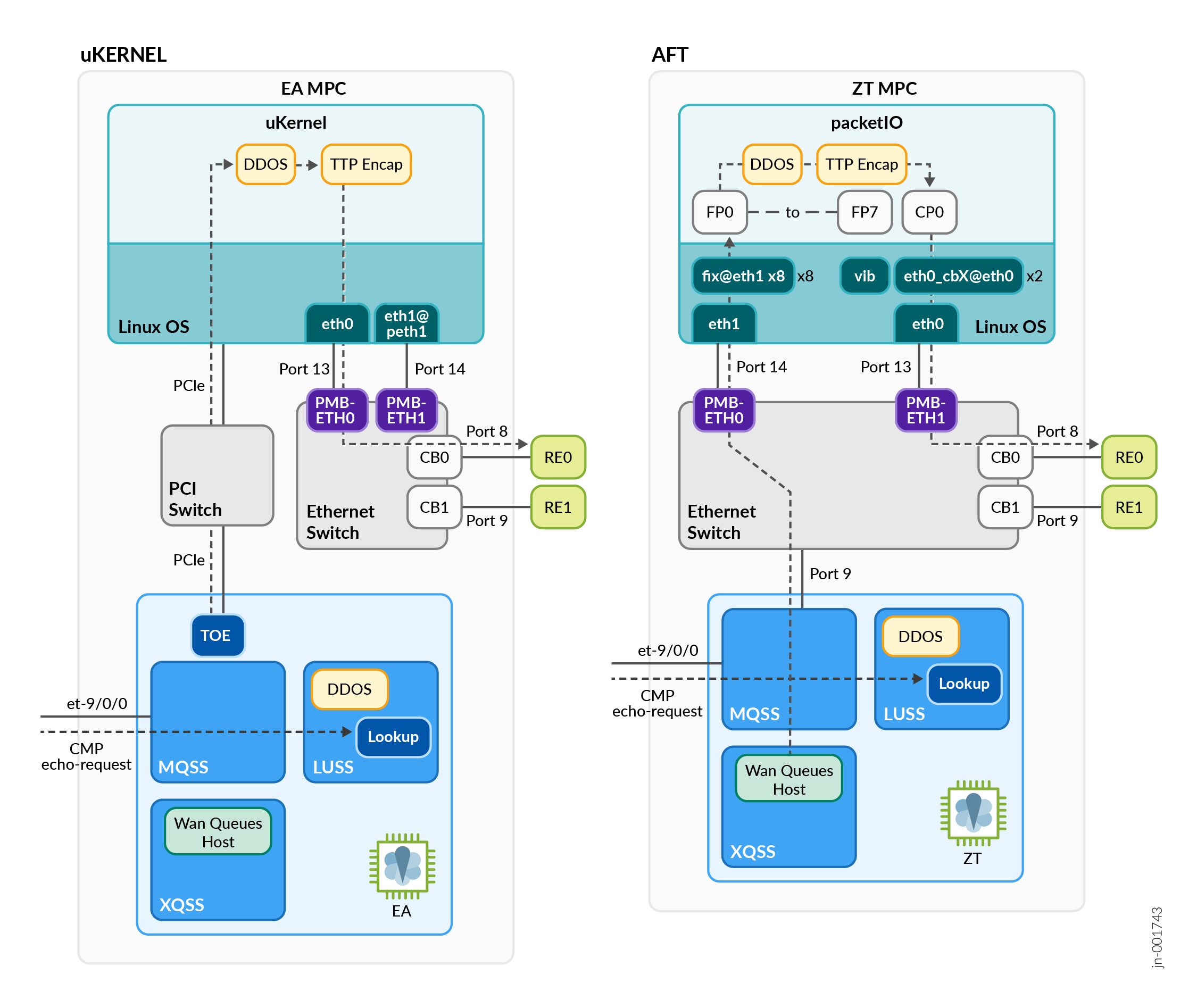
To protect the control plane, use the following mechanisms to filter or drop traffic at the ASIC level before it reaches the RE:
Firewall Filters on lo0.0
Use firewall filters on lo0.0 per address family which is
automatically replicated across all PFE ASICs.
Packet Classification in the Host Path
During ingress processing, the PFE classifies packets in hardware:
- Transit traffic — Forwarded through the data plane (local PFE, fabric, or back‑to‑back)
- Exception traffic — Sent to the host path for control plane processing (for example, packets destined to router IPs, TTL = 1, IP options, or checksum errors)
Key Protection Point for Inbound Traffic
Packets traverse multiple filtering stages before reaching the RE. The most critical control is the loopback firewall filter.
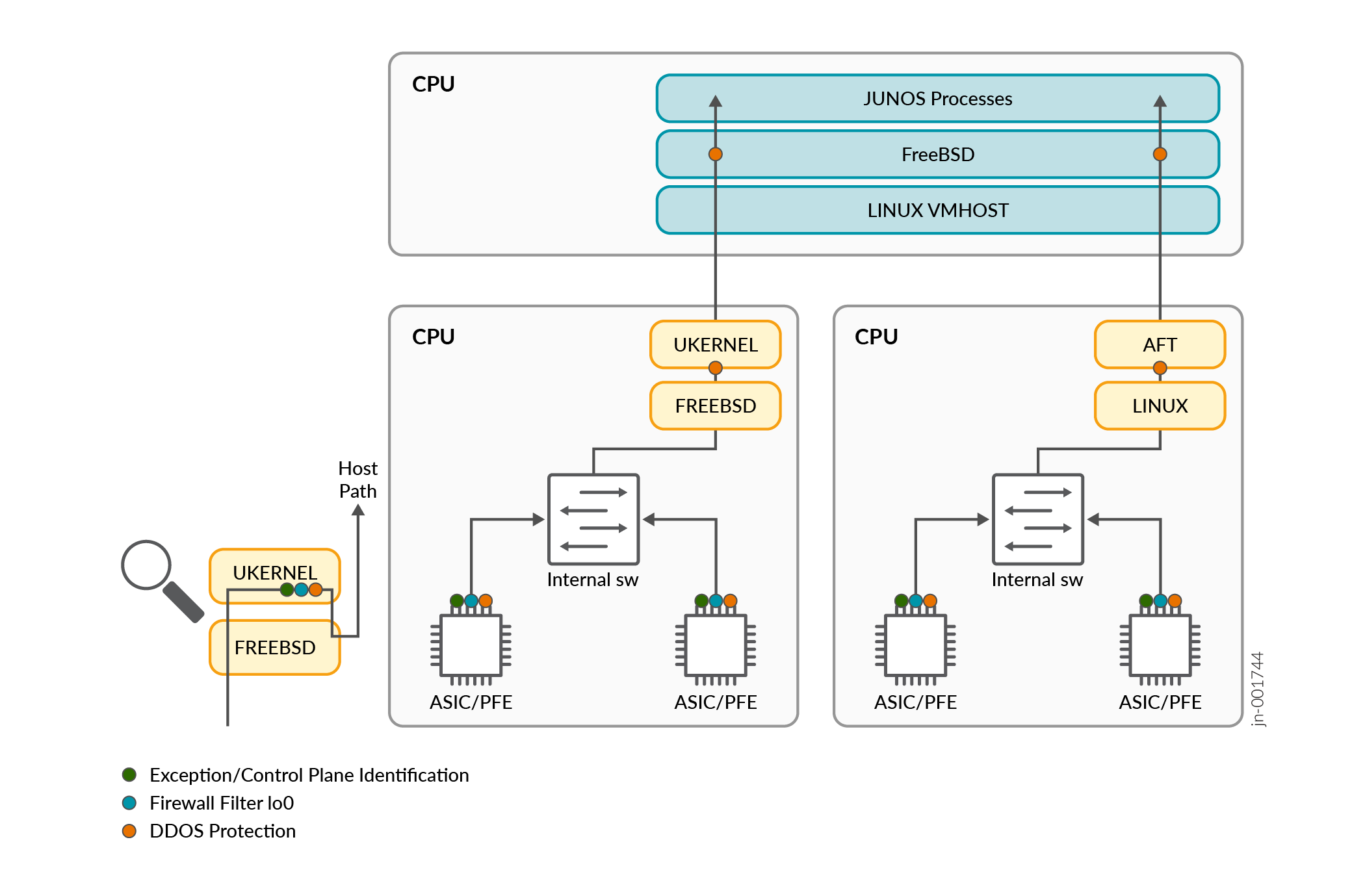
Loopback Firewall Filters
To enable early packet drops in hardware for host-path exception traffic without
affecting transit traffic, apply firewall filters to the lo0.0
interface for the inet, inet6, and
mpls protocol families. Junos OS automatically distributes
these filters to all PFE ASICs:
[edit interfaces]
lo0 {
    unit 0 {
        family inet {
            filter {
                input RE_PROTECT_IN;
            }
        }
        family inet6 {
            filter {
                input RE_PROTECT_INV6;
            }
        }
    }
}
Best Practices
Follow these guidelines when configuring control-plane protection with loopback firewall filters:
- Configure an input firewall filter on each
lo0unit for all relevant protocol families.
- Define separate terms for each protocol (for example, BGP, OSPF, SSH, SNMP, and ICMP).
- For each protocol, include:
- An allow term for trusted sources and required ports
- A deny term for all other traffic
Use Dynamic Prefix Lists with apply-path
-
Use
apply-pathto create prefix lists that automatically reflect the active configuration. This approach simplifies maintenance and ensures that filters stay synchronized with configuration changes.set policy-options prefix-list ALL-BGP apply-path "protocols bgp group <*> neighbor <*>" set policy-options prefix-list ALL-BGP-RI apply-path "routing-instances <*> protocols bgp group <*> neighbor <*>" set policy-options prefix-list BGPV6 apply-path "protocols bgp group <*> neighbor <*:*>" set policy-options prefix-list BGPV6-RI apply-path "routing-instances <*> protocols bgp group <*> neighbor <*:*>" set policy-options prefix-list DNS apply-path "system name-server <*>" set policy-options prefix-list NTP apply-path "system ntp server <*>" set policy-options prefix-list TACPLUS apply-path "system tacplus-server <*>" set policy-options prefix-list LO0 apply-path "interfaces lo0 unit 0 family inet address <*>" set policy-options prefix-list LO0V6 apply-path "interfaces lo0 unit 0 family inet6 address <*:*>"
Example BGP filter terms:
[edit policy-options]
prefix-list BGP {
    apply-path "protocols bgp group <*> neighbor <*>";
}
prefix-list BGP-VRF {
    apply-path "routing-instances <*> protocols bgp group <*> neighbor <*>";
}
[...]
term BGP-ACCEPT {
    from {
        source-prefix-list {
            BGP;
            BGP-VRF;
        }
        protocol tcp;
        port 179;
    }
    then {
        count BGP-ACCEPT;
        accept;
    }
}
term BGP-DROP {
    from {
        protocol tcp;
        port 179;
    }
    then {
        count BGP-DROP;
        discard;
    }
}
Use discard Instead of reject
-
Use
discard(silent drop) to avoid generating responses that can be exploited by scanners.
Enable Counters
-
Configure counters for each term to support monitoring through SNMP or telemetry.
Applly Policers to Open Protocols
-
Rate-limit protocols such as ICMP to protect control-plane resources:
term ICMP {
    from {
        protocol icmp;
        icmp-type [ echo-request echo-reply unreachable time-exceeded ];
    }
    then {
        policer RE-50M;
        accept;
    }
}
term ICMP-DROP {
    from {
        protocol icmp;
    }
    then {
        count ICMP-DROP;
        discard;
    }
}
Add Explicit Default Deny Terms
-
Drop unauthorized traffic directed to router addresses.
-
Add syslog action for further security analysis.
-
Drop all remaining exception traffic.
[edit policy-options]
prefix-list L00 {
    apply-path "interfaces lo0 unit 0 family inet address <*>";
}
[...]
term RJCT-UNTRUST {
    from {
        destination-prefix-list {
            L00;
        }
    }
    then {
        count UNTRUST;
        syslog;
        discard;
    }
}
term RJCT-PUNTED-EXCEPTIONS {
    then {
        count ALL-DROP;
        discard;
    }
}
Configure Logging for Untrusted Traffic
-
Create a dedicated syslog file to capture control-plane drops for auditing and troubleshooting:
[edit]
system {
    syslog {
        file control-plane-drops {
            daemon info;
            explicit-priority;
            archive {
                size 10m;
                files 10;
                world-readable;
            }
        }
    }
}
firewall {
    family inet {
        filter RE-PROTECT {
            term DEFAULT-DENY {
                then {
                    count CP-DROP-V4;
                    log;
                    discard;
                }
            }
        }
    }
}
interfaces {
    lo0 {
        unit 0 {
            family inet {
                filter {
                    input RE-PROTECT;
                }
            }
        }
    }
}
You can monitor firewall term and policer counters in near real time by using
streaming telemetry. Subscribe to the sensor path
/junos/system/linecard/firewall and set the collection interval
to 30 seconds.
DDOS Protection
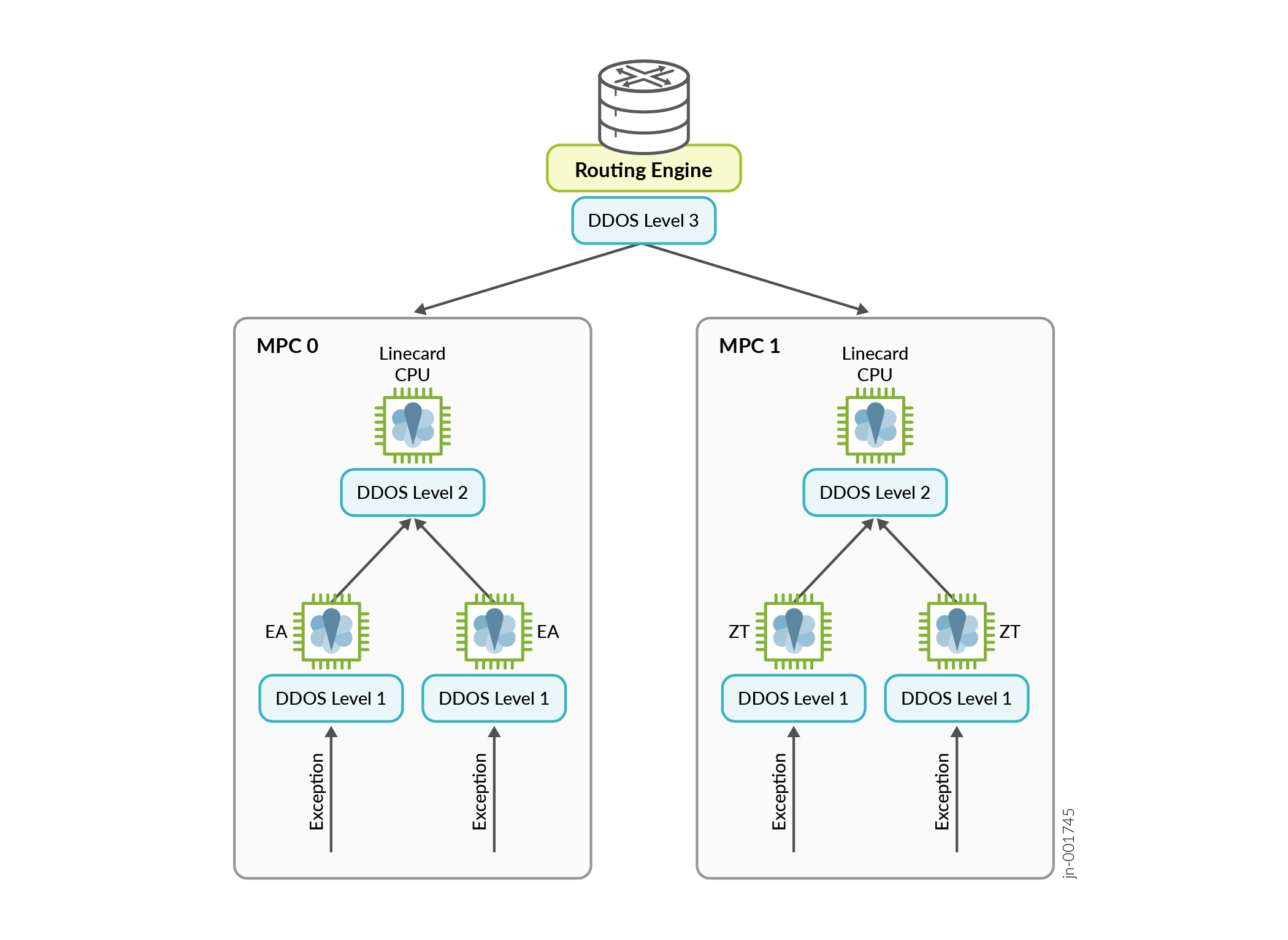
Junos DDoS protection (control-plane DDoS protection) is a distributed, hardware-accelerated and software-based mechanism that protects the Routing Engine (RE) from excessive exception traffic. The system operates in the Packet Forwarding Engine (PFE) on all line cards, dropping malicious or excessive traffic early in the forwarding pipeline before it reaches the RE CPU.
Unlike traditional control plane policing (CoPP), which relies on CPU-based rate limiting at a single point, Junos DDoS protection is fully distributed. Each PFE ASIC, line card CPU, and RE CPU enforces its own set of hardware or software policers that are consistent with RE-level policies. This architecture provides line-rate protection regardless of the number of Flexible PIC Concentrators (FPCs) in the system.
Junos DDoS protection uses a three-stage model:
- Stage 1 (Packet Forwarding Engine hardware)—Applies hardware rate limiters to drop or throttle traffic at the ingress pipeline.
- Stage 2 (line card CPU)—Applies software policers to traffic punted to the line card CPU.
- Stage 3 (Routing Engine CPU)—Applies software policers to protect the Routing Engine CPU.
This layered approach ensures scalable and effective protection of control-plane resources across the entire platform.
Junos DDoS protection supports two types of policers:
- Aggregate (AG) policers—Apply rate limits per protocol (for example, all BGP traffic).
- Specific packet (SP) policers—Apply fine-grained rate limits to individual packet types within a protocol (for example, BGP Open messages versus BGP Update messages).
The interaction between these policers is illustrated in the following example for DHCP protocol protection.
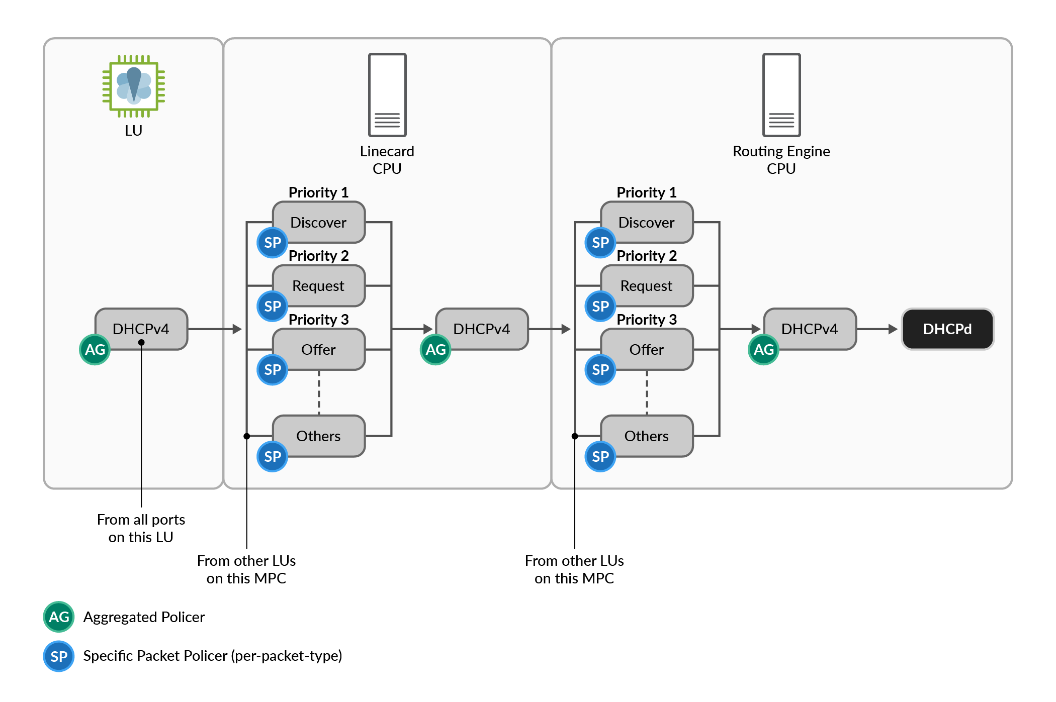
Default DDoS policers use conservative thresholds to reduce the risk of false positives. Adjust these values as needed based on network requirements:
- Bandwidth—Packets per second (PPS)
- Burst size—Number of packets allowed in a burst
- Violation handling—Events generate syslog messages
Configure protocol-specific policers under the following hierarchy:
show ddos-protection protocols dhcpv4 parameters brief
Packet types: 20, Modified: 0
* = User configured value

Protocol   Packet      Bandwidth  Burst  Priority  Recover  Policer  Bypass FPC
group      type        (pps)      (pkts)          time(sec) enabled  aggr. mod
dhcpv4     aggregate   5000       5000    --       300      yes      --    no
dhcpv4     unclass..   300        150     Low      300      yes      no    no
dhcpv4     discover    500        500     Low      300      yes      no    no
dhcpv4     offer       1000       1000    Low      300      yes      no    no
dhcpv4     request     1000       1000    Medium   300      yes      no    no
dhcpv4     decline     500        500     Low      300      yes      no    no
dhcpv4     ack         500        500     Medium   300      yes      no    no
dhcpv4     nak         500        500     Low      300      yes      no    no
dhcpv4     release     2000       2000    High     300      yes      no    no
dhcpv4     inform      500        500     Low      300      yes      no    no
dhcpv4     renew       2000       2000    High     300      yes      no    no
dhcpv4     forcerenew  2000       2000    High     300      yes      no    no
dhcpv4     leasequery  2000       2000    High     300      yes      no    no
dhcpv4     leaseuna..  2000       2000    High     300      yes      no    no
dhcpv4     leaseunk..  2000       2000    High     300      yes      no    no
dhcpv4     leaseact..  2000       2000    High     300      yes      no    no
dhcpv4     bootp       300        300     Low      300      yes      no    no
dhcpv4     no-msgtype  1000       1000    Low      300      yes      no    no
dhcpv4     bad-pack..  0          0       Low      300      yes      no    no
dhcpv4     rebind      2000       2000    High     300      yes      no    no
To monitor DDoS protection statistics, run the following command:
show ddos-protection protocols dhcpv4 statistics brief
Packet types: 20, Received traffic: 0, Currently violated: 0

Protocol   Packet      Received      Dropped      Rate    Violation State
group      type        (packets)     (packets)    (pps)   counts
dhcpv4     aggregate   0             0            0       0       ok
dhcpv4     unclass..   0             0            0       0       ok
dhcpv4     discover    0             0            0       0       ok
dhcpv4     offer       0             0            0       0       ok
dhcpv4     request     0             0            0       0       ok
dhcpv4     decline     0             0            0       0       ok
dhcpv4     ack         0             0            0       0       ok
dhcpv4     nak         0             0            0       0       ok
dhcpv4     release     0             0            0       0       ok
dhcpv4     inform      0             0            0       0       ok
dhcpv4     renew       0             0            0       0       ok
dhcpv4     forcerenew  0             0            0       0       ok
dhcpv4     leasequery  0             0            0       0       ok
dhcpv4     leaseuna..  0             0            0       0       ok
dhcpv4     leaseunk..  0             0            0       0       ok
dhcpv4     leaseact..  0             0            0       0       ok
dhcpv4     bootp       0             0            0       0       ok
dhcpv4     no-msgtype  0             0            0       0       ok
dhcpv4     bad-pack..  0             0            0       0       ok
dhcpv4     rebind      0             0            0       0       ok
You can also monitor DDOS protection statistics via streaming telemetry by
subscribing to the sensor path: /junos/system/linecard/ddos.
Recommended interval rate is 60 seconds.
For more information on securing the control plane on a MX device, see Security Services Administration Guide.