
End-to-End Layer 2 Connectivity Using VPLS-Based Layer 2 VPN
This section describes an enterprise WAN edge use case with the ACX7000 family of routers. The ACX7000 family of routers includes ACX7020, ACX7024, ACX7024X, ACX7100, ACX7332, ACX7348, and ACX7509 routers.
This section describes the essential configurations to establish end-to-end Layer 2 services across enterprise WAN using VPLS-based Layer 2 VPN. Use these configurations to seamlessly integrate customer networks with a resilient service-provider backbone.
You can use the following sample topology for your reference:
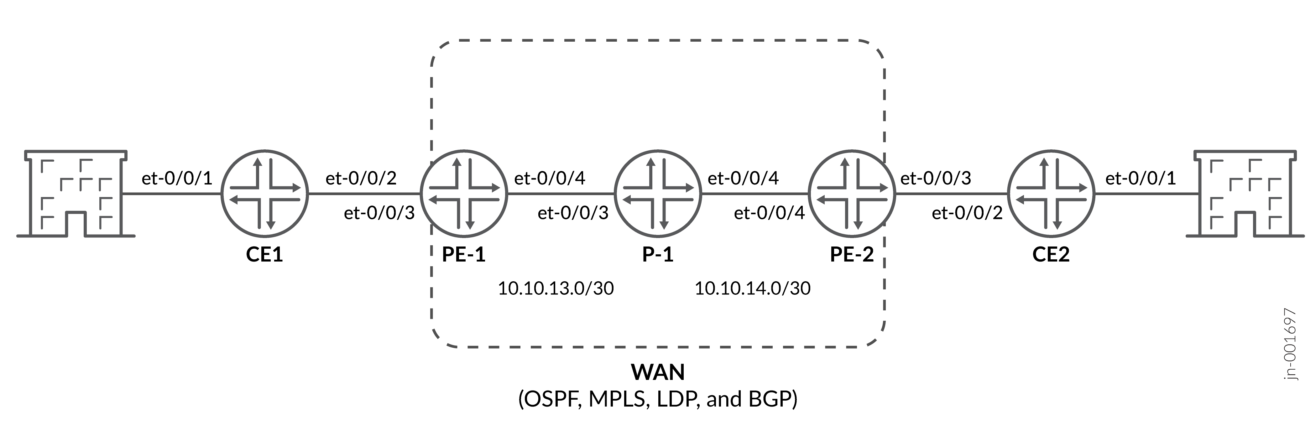
The topology shows two customer edge devices (CE1 and CE2) connected to their respective hosts and an enterprise WAN comprising two provider edge devices (PE1 and PE2) and one provider device (P1).
Benefits of using VPLS-based Layer 2 VPN:
-
Transparent Layer 2 connectivity—Enables geographically distributed sites to operate as if they are on the same Ethernet LAN or VLAN.
-
Ethernet-optimized service—Designed specifically for Ethernet services, making it ideal for enterprise LAN extension and data center interconnect use cases.
-
Service provider isolation—Keeps customer traffic logically separated using MPLS labels and VPN identifiers.
-
Scalability—Leverages MPLS to scale Layer 2 services efficiently across large WANs while keeping customer MAC address learning at provider edge, reducing core network complexity and improving overall scalability.
Customer Edge Device Configurations
Here is the configuration on the CE1 device:
Configure a unique system identity and loopback addressing.
set system host-name CE1
set routing-options router-id 172.16.0.1
set interfaces lo0 unit 0 family inet address 172.16.0.1/24
Configure CE interfaces in access or trunk mode to connect hosts and provider edge devices.
CE to host interfaces:
set interfaces et-0/0/1 unit 0 family ethernet-switching interface-mode access
CE to PE interfaces:
set interfaces et-0/0/2 unit 0 family ethernet-switching interface-mode trunk
Create VLANs and associate them with IRB interfaces to enable Layer 2 switching and Layer 3 routing.
set vlans VLAN100 vlan-id 100
set vlans VLAN100 l3-interface irb.100
set interfaces irb unit 100 family inet address 192.168.10.1/24
set interfaces et-0/0/1 unit 0 family ethernet-switching vlan members VLAN100
set interfaces et-0/0/2 unit 0 family ethernet-switching vlan members VLAN100
Provider Edge and Provider Device Configurations
Configure system parameters and loopback interfaces on provider edge and provider devices.
set system host-name PE1
set routing-options router-id 172.16.0.2
set interfaces lo0 unit 0 family inet address 172.16.0.2/24
Repeat this configuration on other provider edge and provider devices as applicable.
Assign an autonomous system number on provider edge devices.
set routing-options autonomous-system 65000
Repeat this configuration on other provider edge devices as applicable.
Configure core-facing interfaces on provider edge and provider devices for backbone connectivity.
On PE1:
set interfaces et-0/0/4 unit 0 family inet address 10.10.13.1/24
Repeat this configuration on other provider edge devices as applicable.
On P1:
set interfaces et-0/0/3 unit 0 family inet address 10.10.13.2/24
set interfaces et-0/0/4 unit 0 family inet address 10.10.14.1/24
Repeat this configuration on other provider devices as applicable.
Configure customer-facing interfaces on provider edge devices with appropriate VLAN tagging and encapsulation.
set interfaces et-0/0/4 unit 100 encapsulation vlan-vpls
set interfaces et-0/0/4 unit 100 vlan-id 100
set interfaces et-0/0/4 flexible-vlan-tagging
set interfaces et-0/0/4 encapsulation flexible-ethernet-services
Repeat this configuration on other provider edge devices as applicable.
Enable OSPF, MPLS, and LDP on provider edge and provider devices to establish the transport underlay across the provider network.
set protocols ospf area 0 interface lo0.0
set protocols ospf area 0 interface et-0/0/0.0
set protocols ospf area 0 interface et-0/0/1.0
set protocols mpls interface et-0/0/0.0
set protocols mpls interface et-0/0/1.0
set protocols ldp interface lo0.0
set protocols ldp interface et-0/0/0.0
set protocols ldp interface et-0/0/1.0
Repeat this configuration on other provider edge and provider devices as applicable.
Configure Multiprotocol BGP (MP-BGP) sessions on the provider edge devices to enable exchange of BGP-based VPLS signaling and autodiscovery information.
set protocols bgp group IBGP-VPLS type internal
set protocols bgp group IBGP-VPLS local-address 172.16.0.2
set protocols bgp group IBGP-VPLS inet-vpn unicast
set protocols bgp group IBGP-VPLS family l2vpn signaling
set protocols bgp group IBGP-VPLS family l2vpn auto-discovery-only
set protocols bgp group IBGP-VPLS neighbor 172.16.0.3 peer-as 65000
Repeat this configuration on other provider edge devices as applicable.
Create and configure a VPLS routing instance for customer Layer 2 VPN services on provider edge devices.
set routing-instances CUST-VPLS-100 instance-type virtual-switch
set routing-instances CUST-VPLS-100 route-distinguisher 65000:100
set routing-instances CUST-VPLS-100 vrf-target target:65000:100
set routing-instances CUST-VPLS-100 protocols vpls site-range 100
set routing-instances CUST-VPLS-100 protocols vpls no-tunnel-services
set routing-instances CUST-VPLS-100 protocols vpls vpls-id 100
set routing-instances CUST-VPLS-100 vlans VLAN100 vlan-id 100
set routing-instances CUST-VPLS-100 vlans VLAN100 interface et-0/0/4.100
Repeat this configuration on other provider edge devices as applicable.
Configure VPLS site identifiers to uniquely identify the provider edge participation within the VPLS instance.
set routing-instances CUST-VPLS-100 protocols vpls site PE1 site-identifier 1
set routing-instances CUST-VPLS-100 protocols vpls site PE1 interface et-0/0/4.100
Repeat this configuration on other provider edge devices as applicable.
For more information on Layer 2 services, see Layer 2 VPNs and VPLS User Guide for Routing Devices.
For more details, see Enterprise WAN Validated Designs.
Verification
The following table introduces a list of show commands which you can
use to verify the configuration in this example.
| What to Check | Command | Output Expected |
|---|---|---|
|
OSPF adjacencies |
All neighbors showing full adjacency across PE and P devices. |
|
|
BGP sessions |
Internal BGP (IBGP) sessions to all PE devices are established and Layer 2 VPN table is active. |
|
|
MPLS-enabled links |
All core MPLS interfaces are up. |
|
|
LDP peers/sessions |
Neighbor adjacencies and LDP sessions are established. |
|
|
Transport and service labels |
LDP and VPLS entries with LSI bindings. |
|
|
VPLS pseudowires |
All remote sites with incoming and outgoing labels and confirmation that VPLS pseudowires are up. |