BGP Subnets
The BGP subnets list can be used to list prefixes, or subnetworks (whose router configuration files are unavailable) originated from a particular router or AS node. Various BGP attributes associated with the subnetwork can be defined in the subnet file.
If useliveBGPrtbl=1 is set in the dparam file, or in Tools > Options > Design, Path Placement > BGP, then the subnets information will be ignored.
The subnet file can be viewed from the File Manager or from Network > Protocols > BGP > BGP Subnets... menu. To add, modify, or delete BGP subnets in the subnet file, first switch into the Modify action mode. Then bring up the BGP Subnets window via the Modify > Protocols > BGP > BGP Subnets... menu. The following figure shows a subnet entry for AS node, AS1301, being modified.
Figure 1: Modifying a BGP Subnet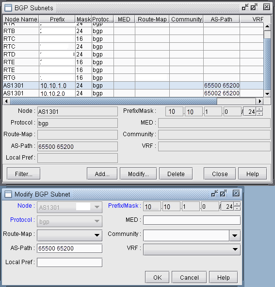
-
Note the Protocol field, which defaults to bgp. Specifying “bgp” indicates that this is the prefix advertised from the router. In-policies still need to be applied to this route by the router receiving the route. Specifying “bgptbl” in this field indicates the route that is in the router’s routing table. It has already been accepted by the router’s in policy, but may or may not be the preferred route. This option is used for routes received from other Autonomous Systems, since their configuration files may not be available.
To illustrate how to use the BGP subnet list (accessed via Network > Protocols > BGP > BGP Subnets...), a sample network and the corresponding BGP subnet list are shown in the following two figures. Note that within the BGP subnet list, ASnode AS1301 is declaring that it can reach subnet 10.10.1.0/24, which has an AS_PATH attribute that includes 65500. ASnode AS1301 is also declaring that it can reach subnet 10.10.2.0/24, which has an AS_PATH attribute that includes 65002.
Figure 2: View BGP Subnets Window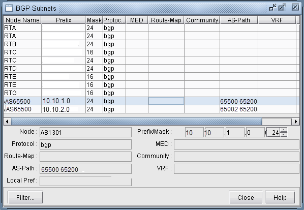 Figure 3: Main View and BGP View of the network
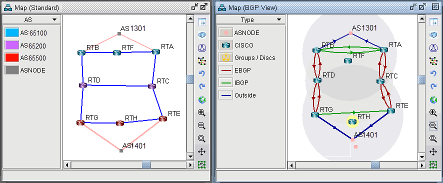
-
To see the BGP InPolicy defined at a router RTE, bring up the BGP Neighbors table and switch to the In Policy tab, as shown in the following figure. In this particular example, the InPolicy at router RTE is defined by a Cisco route-map and says that if an incoming route has 65001 included in its AS_PATH attribute, then set the LOCAL_PREF attribute to 123; otherwise, set the LOCAL_PREF attribute to 89. The InPolicy at router RTG is the same except that 65002 is matched for instead of 65001.
Figure 4: BGP In Policy for RTE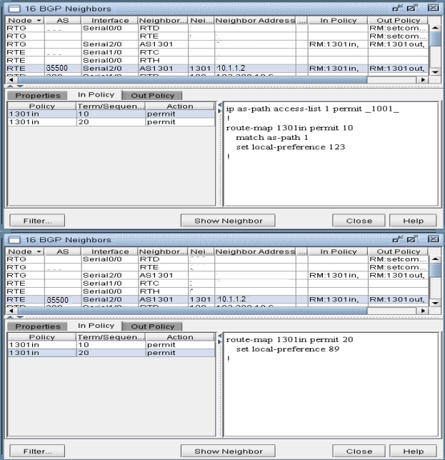
-
Continuing with our example, we bring up our BGP routing table to verify that the LOCAL_PREF attribute got set correctly to 123 for AS1301’s subnetwork 10.10.2.0/24, which has 65002 included in its AS_PATH attribute.
Figure 5: BGP Routing table from RTH to AS1301 subnet 10.10.2.0/24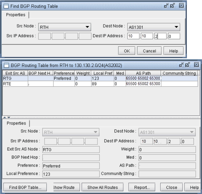 Note:
Note:In Internet routing, community is another commonly-used attribute to tag a particular route. Each service provider can define its own policy based on this attribute of the incoming route. The subnet file helps the user to simulate routing behavior to various Internet destinations.
-
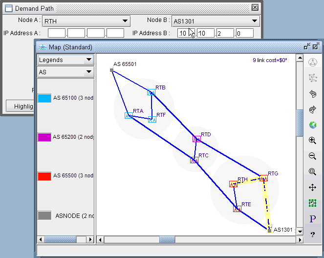
Finally, we can do a path trace from a router, say RTH, in AS65500 (which includes routers RTH, RTE, RTG) to AS1301’s subnetwork 10.10.2.0 and verify that RTG is indeed the preferred exit point for AS65500, as indicated by the higher LOCAL_PREF value of 123. The following figure shows the path trace.
Figure 6: Path trace illustrating the RTG being the preferred exit point