Changes Not Reflected in the GUI
Problem
The changes that you made in the live network do not appear in the GUI.
Solution
Ideally, the network model in the Paragon Pathfinder database is in sync with the live network. However, the network model might become out of sync with the live network for various reasons. For example, when the network model audit has unresolved discrepancies, the node ISO network entity title (NET) address changes, the node ID changes, and so on. To solve the problem, you can either synchronize the network model or reset the network model from the Pathfinder page (Configuration > Network Settings > Pathfinder Settings > Advanced Settings):
You can synchronize and reset the network model from the GUI only if your user role has the permissions to perform the Sync and Reset actions, respectively.
Perform the Reset action only with the supervision of Juniper Networks Technical Assistance Center (JTAC). This action erases the network data model and the data provided through the Add or Modify actions in the network information table. Therefore, reserve this action for a lab setting (not a production setting).
-
Synchronize the network model—Perform this action if you don't want to lose user planning data when you synchronize the network model with the live network. The Path Computation Server (PCS) still requests a topology synchronization, but the Toposerver does not delete the existing elements.
-
Reset the network model—Perform this action only if the sync operation does not resolve the discrepancies in the network model and you want to start over from scratch with your topology.
Synchronize the Network Model
When you synchronize the network model:
- Information associated with the network model remains intact. This includes information such as the information associated with the nodes, links, label-switched paths (LSPs), interfaces, shared risk link groups (SRLG), and user-defined parameters. Nothing is purged from the database.
- The network model is repopulated with live data learned from topology acquisition.
Figure 1 illustrates the flow from the PCS to the containerized routing protocol process (daemon) [cRPD] and Path Computation Element (PCE) server. It also illustrates the updates coming back to the Toposerver.
Reset the Network Model
If you execute the Reset Network Model operation, you will lose changes that you've made to the database. In a multi-user environment, one user might reset the network model without the knowledge of the other users.
When you reset the network model:-
When you request a reset, the request goes from the PCS to the Toposerver.
Following is a sample of the PCS log that indicates that a topology reset is requested:
Note:The logs that you view may differ from the logs in this document. The logs change based on the installed version of Paragon Automation.
Apr 25 10:54:50.385008 user-PCS PCServer [->TopoServer] Request topology reset
- Information associated with the network model (nodes, links, LSPs, interfaces, SRLGs, and
user-defined parameters) is purged from the database.Note:
Device profiles are not purged from the database.
The following sample of the Toposerver log indicates that the database elements are being removed:
Apr 25 10:54:50.386912 user-PCS TopoServer  Truncating pcs.links...
Apr 25 10:54:50.469722 user-PCS TopoServer  Truncating pcs.nodes...
Apr 25 10:54:50.517501 user-PCS TopoServer  Truncating pcs.lsps...
Apr 25 10:54:50.753705 user-PCS TopoServer  Truncating pcs.interfaces...
Apr 25 10:54:50.806737 user-PCS TopoServer  Truncating pcs.facilities...
-
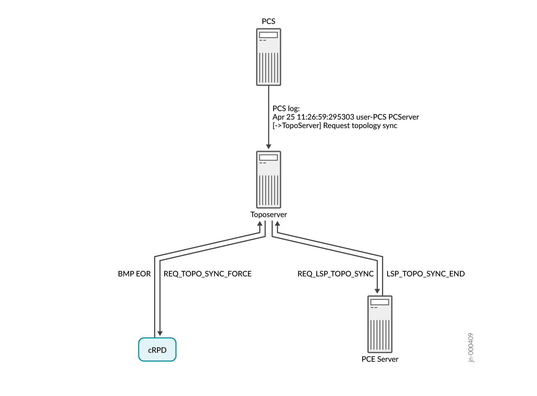
The Toposerver then requests a synchronization with both the cRPD (to retrieve the topology nodes and links) and the PCE server (to retrieve the LSPs). In this way, the Toposerver relearns the topology, but any user updates are missing. Figure 2 illustrates the flow from the topology reset request to the request for synchronization with the cRPD and the PCE Server.
Figure 2: Reset Model Request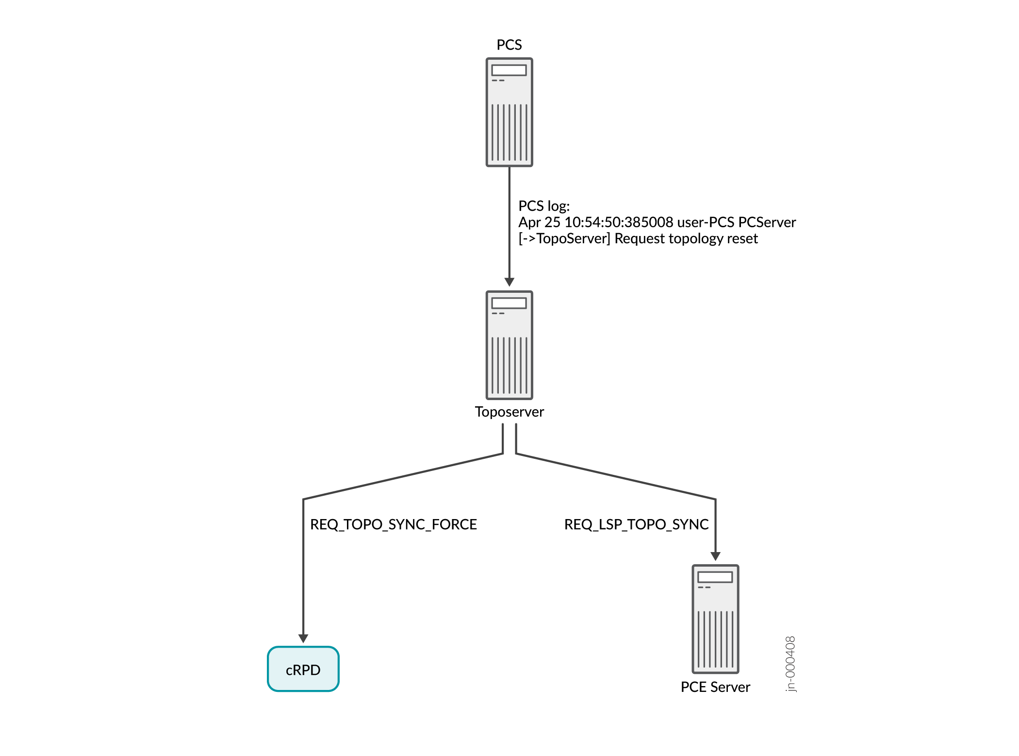
-
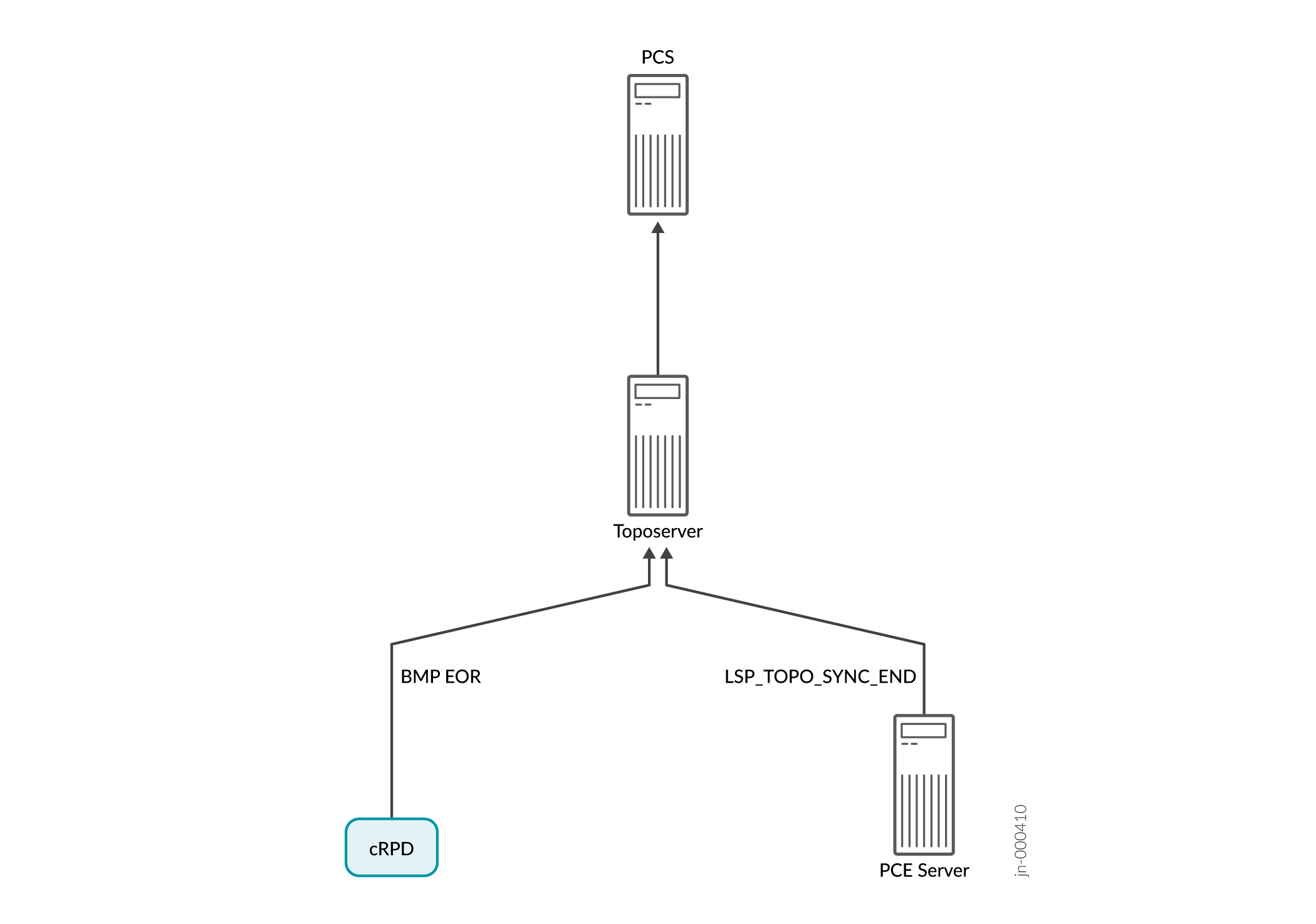
Upon receiving the synchronization requests, cRPD and the PCE server return topology updates that reflect the current live network.
The following sample of the PCS log indicates that the topology updates are being added to the database:
Apr 25 10:54:52.237882 user-PCS PCServer  [<-TopoServer] Update Topology
Apr 25 10:54:52.237894 user-PCS PCServer  [<-TopoServer] Update Topology Persisted Nodes (0)
Apr 25 10:54:52.238957 user-PCS PCServer  [<-TopoServer] Update Topology Live Nodes (7)
Apr 25 10:54:52.242336 user-PCS PCServer  [<-TopoServer] Update Topology Persisted Links (0)
Apr 25 10:54:52.242372 user-PCS PCServer  [<-TopoServer] Update Topology live Links (10)
Apr 25 10:54:52.242556 user-PCS PCServer  [<-TopoServer] Update Topology Persisted Facilities (1)
Apr 25 10:54:52.242674 user-PCS PCServer  [<-TopoServer] Update Topology Persisted LSPs (0)
Apr 25 10:54:52.279716 user-PCS PCServer  [<-TopoServer] Update Topology Live LSPs (47)
Apr 25 10:54:52.279765 user-PCS PCServer  [<-TopoServer] Update Topology Finished
Figure 3 illustrates the return of topology updates from the cRPD and the PCE Server to the Toposerver and the PCS.