Configuring the ML2 Plug-in
Juniper ML2 drivers support the following types of virtual networks:
VLAN based network
VXLAN based tunneled network with EVPN by using Hierarchical Port Binding
By using the features such as LAG and MC-LAG, ML2 drivers support the orchestration of aggregated links that connect the OpenStack nodes to the ToR switches.
Configuring the ML2 VLAN Plug-in
Juniper ML2 VLAN plug-in supports configuring VLAN of the network of each tenant on the corresponding switch port attached to the compute node. VM migration is supported from OpenStack Neutron version 2.7.1 onwards.
Supported Devices
EX series and QFX series devices.
Plug-in Configuration
To configure OpenStack Neutron to use VLAN type driver:
On the OpenStack Controller, open the file
/etc/neutron/neutron.confand update as follows:core_plugin = neutron.plugins.ml2.plugin.Ml2Pluginorcore_plugin = neutron.plugins.ml2.plugin_pt_ext.Ml2PluginPtExtOn Openstack Controller, update the ML2 configuration file
/etc/neutron/plugins/ml2/ml2_conf.inito set Juniper ML2 plug-in as the mechanism driver:[ml2] type_drivers = vlan mechanism_drivers = openvswitch,juniper tenant_network_types = vlan
Specify the VLAN range and the physical network alias to be used.
[ml2_type_vlan]
network_vlan_ranges = physnet1:1001:1200
Restart the OpenStack neutron server for the changes to take effect.
Login to OpenStack GUI and create VLAN based network and launch VMs. You can view the VLAN IDs of the OpenStack network are created on the switch and mapped to the interfaces that are configured through the
jnpr_switchport_mappingcommand.
Configuring ML2 VXLAN Plug-in with EVPN
ML2 EVPN driver is based on Neutron hierarchical port binding design. It configures the ToR switches as VXLAN endpoints (VTEPs), which is used to extend VLAN based L2 domain across routed networks.
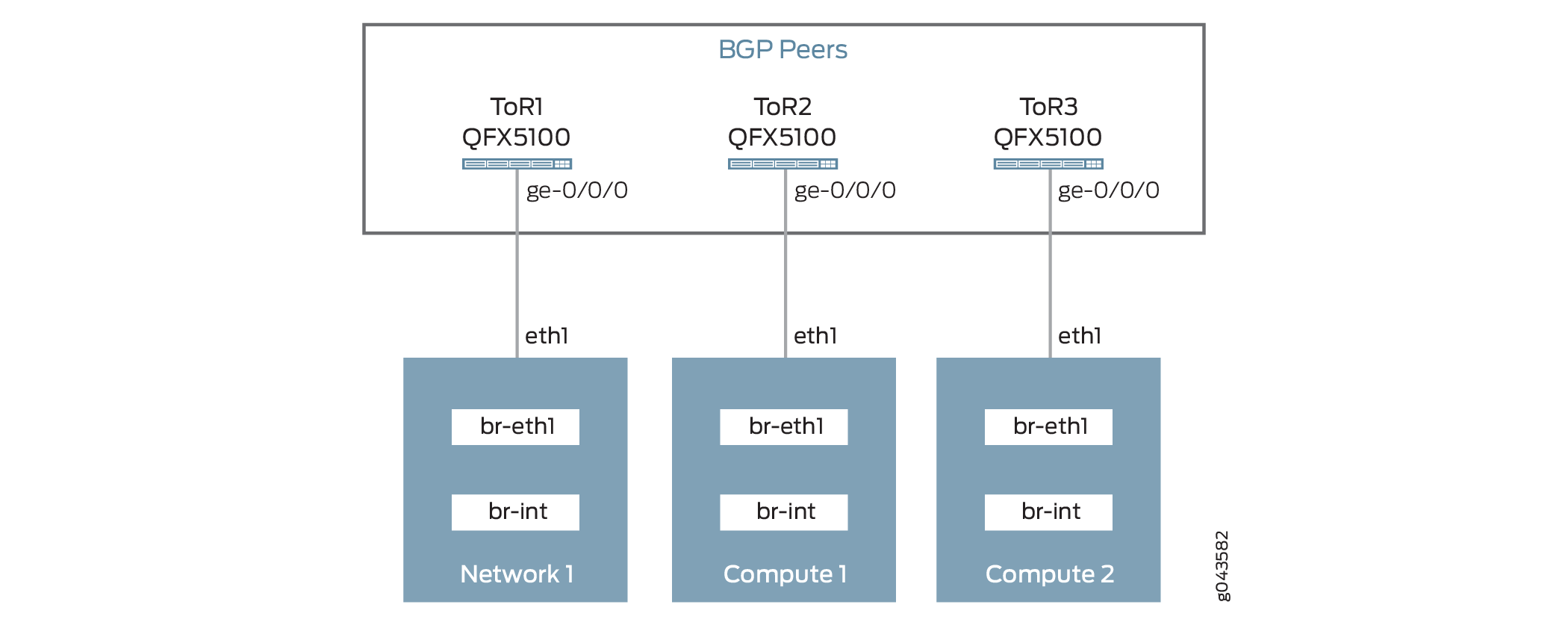
To provide L2 connectivity between the network ports and compute nodes, the L2 packets are Tagged with VLANs and sent to the Top of Rack (TOR) switch. The VLANs used to tag the packets are only locally significant to the TOR switch (Switch Local VLAN).
At the ToR switch, the Switch Local VLAN is mapped into a global VXLAN ID. The L2 packets are encapsulated into VXLAN packets and sent to the virtual tunnel endpoint (VTEP) on the destination node, where they are de-encapsulated and sent to the destination VM.
To make the L2 connectivity between the endpoints work with VXLAN, each endpoint must be informed about the presence of destination VM and VTEP. EVPN uses a BGP-based control plane to learn this information. The plug-in assumes that the ToRs are setup with BGP-based peering.
Refer to Junos documentation for configuring BGP on the ToR switches available at BGP Configuration Overview.
Supported Devices
QFX 5100 only
Plug-in Configuration
To install the Juniper neutron plug-in on the neutron server node, complete the following steps:
Configuring ML2 Driver with Link Aggregation
You can use Link Aggregation (LAG) between an OpenStack compute node and a Juniper switch to improve network resiliency.
Plug-in Configuration
Figure 2 describes the connectivity of OpenStack compute node to the Top of Rack (TOR) switch.

To configure LAG on Juniper ToR switches, refer to the following link:
Configuring Aggregated Ethernet Links (CLI Procedure)
To configure LAG on the OpenStack compute node:
Configuring ML2 Driver with Multi-Chassis Link Aggregation
You can configure Multi-Chassis Link Aggregation (MC-LAG) and use it with Juniper Neutron plug-ins.

Plugin Configuration
To configure MC-LAG on Juniper switches, refer to the following link:
Configuring Multichassis Link Aggregation on EX Series Switches
To configure LAG on Openstack compute: