Setting Up L2 and L3 Topologies
Figure 1 illustrates the L2 topology.
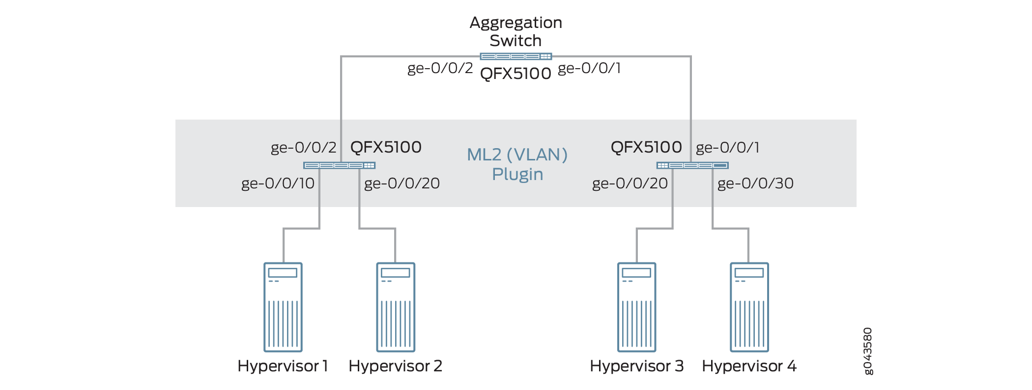
Figure 2 shows switches such as Switch1, Switch2, and Aggregation Switch, which you can configure to set up the topology.
To set up a topology, complete the following steps:
On the Aggregation Switch, set ge-0/0/1 and ge-0/0/2 interfaces to Trunk All mode.
On Switch 1, set ge-0/0/2 interface to Trunk All mode and enable vlan-tagging on ge-0/0/10 and ge-0/0/20 interfaces.
On Switch 2, set ge-0/0/1 interface to Trunk All mode and enable vlan-tagging on ge-0/0/30 and ge-0/0/20 interfaces.
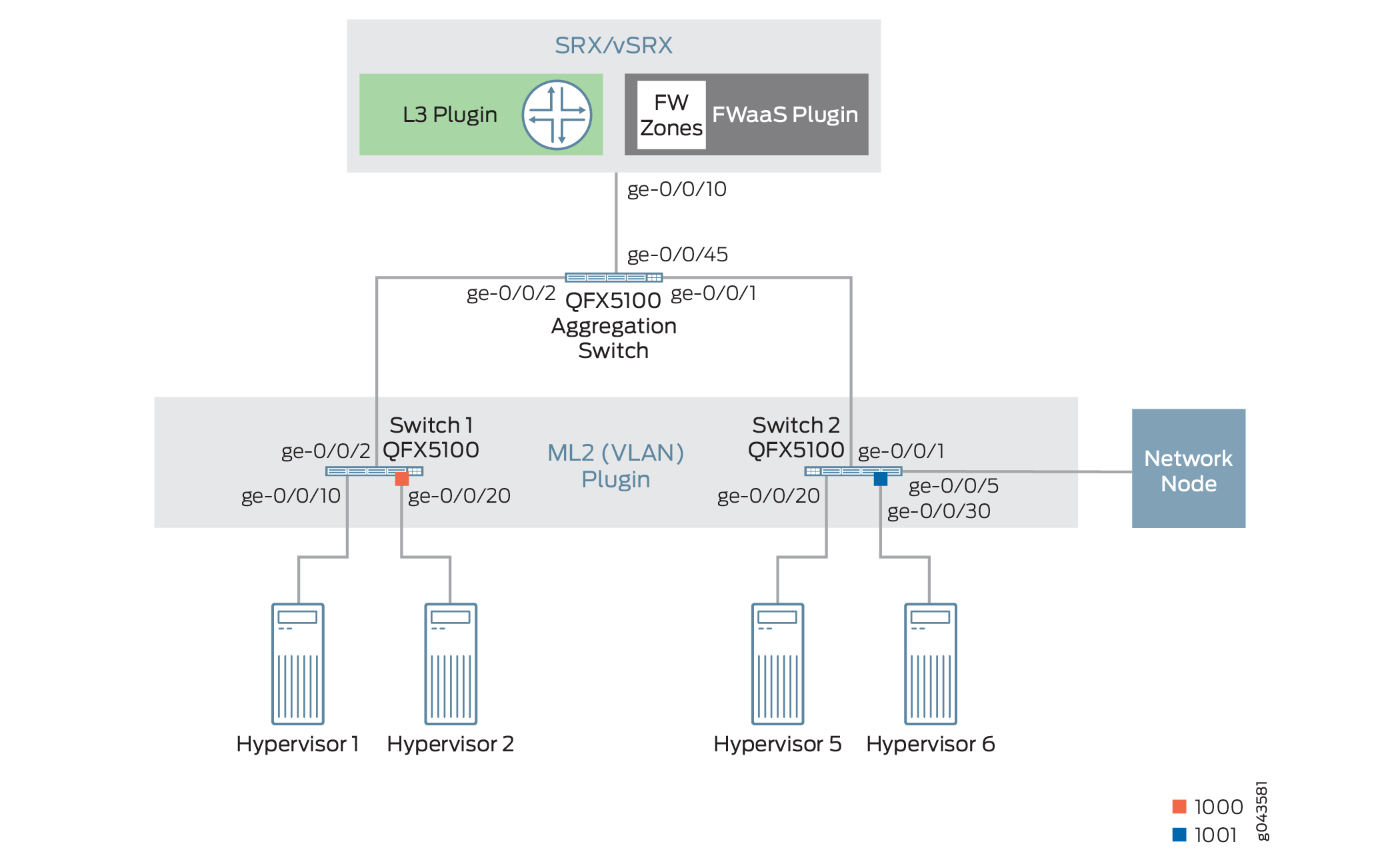
In Figure 2, the SRX acts as both a router as well as a firewall.
Setting Up the Physical Topology
To set up the physical topology:
- To configure the Juniper Networks plug-in with the reference
physical topology, use the commands listed in Table 1:
Juniper Neutron plug-ins include CLI tools, which enable the administrator to define the network topology. The plug-ins depend on the topology definition to carry out network orchestration.
Table 1: CLI Tools Name
Description
jnpr_device
Add device details
jnpr_nic_mapping
Add a mapping between physical network alias (ex: Physnet1) to the corresponding ethernet interface on the node.
jnpr_switchport_mapping
Add a mapping between the compute or network Node and its Ethernet Interface to the switch and the port that it is connected to.
jnpr_device_port
Define the downlink port of the router or firewall on which routed VLAN interface (RVI)RVI for each tenant VLAN is created.
jnpr_allocate_device
Define allocation of router and firewall to a tenant or group of tenants.
jnpr_vrrp_pool
Define the VRRP pool.
- To add devices to the topology, run the following command
on the OpenStack Neutron controller:Note:
Use a login credential with super-user class privilege on the devices that are added to the topology.
admin@controller:~$ jnpr_device add -d device-name or device-IP-address -c {switch, router, firewall} -u username -p device-password - To add and view switches that are added to the topology,
run the following command on the OpenStack Neutron controller:Note:
In the physical topology, Switch1 and Switch2 are connected to the hypervisors.
- To add Switch1 to the topology, run the following command
on the OpenStack Neutron controller::
admin@controller:~$ jnpr_device add -d switch1.juniper.net -c switch -u root -p root-password
+---------------------+---------------+-------------+---------+-------+------+---------------+
|        Device       |       Ip      | Device Type |  model  | login | vtep | vrrp_priority |
+---------------------+---------------+-------------+---------+-------+------+---------------+
| switch1.juniper.net | 10.107.52.136 |    switch   | qfx3500 |  root |  0   |       0       |
+---------------------+---------------+-------------+---------+-------+------+---------------+
- To add Switch2 to the topology, run the following command
on the OpenStack Neutron controller:
admin@controller:~$ jnpr_device add -d switch2.juniper.net -c switch -u root -p password
+---------------------+---------------+-------------+---------+-------+------+---------------+
|        Device       |       Ip      | Device Type |  model  | login | vtep | vrrp_priority |
+---------------------+---------------+-------------+---------+-------+------+---------------+
| switch2.juniper.net | 10.107.52.137 |    switch   | qfx3500 |  root |  0   |       0       |
+---------------------+---------------+-------------+---------+-------+------+---------------+
- To view the switches that are added to the topology, run
the following command on the OpenStack Neutron controller:
admin@controller:~$ jnpr_device list
+---------------------+---------------+-------------+---------+-------+------+---------------+
|        Device       |       Ip      | Device Type |  model  | login | vtep | vrrp_priority |
+---------------------+---------------+-------------+---------+-------+------+---------------+
| switch1.juniper.net | 10.107.52.136 |    switch   | qfx3500 |  root |  0   |       0       |
| switch2.juniper.net | 10.107.52.137 |    switch   | qfx3500 |  root |  0   |       0       |
+---------------------+---------------+-------------+---------+-------+------+---------------+
- To add Switch1 to the topology, run the following command
on the OpenStack Neutron controller::
- To add routers to the topology, run the following command
on the OpenStack Neutron controller:Note:
In the physical topology shown in Figure 2, the SRX acts as both a router as well as a firewall.
admin@controller:~$ jnpr_device add -d srx.juniper.net -c router -u root -p password
+-----------------+---------------+-------------+-------+-------+------+---------------+
|      Device     |       Ip      | Device Type | model | login | vtep | vrrp_priority |
+-----------------+---------------+-------------+-------+-------+------+---------------+
| srx.juniper.net | 10.107.23.103 |    router   |   srx  |  root |  0   |       0      |
+-----------------+---------------+-------------+-------+-------+------+---------------+
- To add firewall to the topology, run the following command
on the OpenStack Neutron controller:
admin@controller:~$ jnpr_device add -d srx.juniper.net -c firewall -u root -p password
+-----------------+---------------+-------------+-------+-------+------+---------------+
|      Device     |       Ip      | Device Type | model | login | vtep | vrrp_priority |
+-----------------+---------------+-------------+-------+-------+------+---------------+
| srx.juniper.net | 10.107.23.103 |   firewall  |   srx  |  root |  0   |       0      |
| srx.juniper.net | 10.107.23.103 |    router   |   srx  |  root |  0   |       0      |
+-----------------+---------------+-------------+-------+-------+------+---------------+
- Define the NIC to physical network mapping for each hypervisor.
In OpenStack, you generally define an alias for the physical network and its associated bridge by using the following configuration in
/etc/neutron/plugins/ml2/ml2_conf.inifile on the network node and all the compute nodes:[ovs] tenant_network_type = vlan bridge_mappings = physnet1:br-eth1
Because you can connect the bridge br-eth1 to any physical interface, you must add the link between the bridge br-eth1 and the physical interface to the topology by entering following command:
admin@controller:~$ jnpr_nic-mapping add -H compute-hostname -b physical-network-alias-name -n NIC
- To add Hypervisor 1 to the topology, run the following
command on the OpenStack Neutron controller:
admin@controller:~$ jnpr_nic_mapping add -H hypervisor1.juniper.net -b physnet1 -n eth1
Adding mapping
+---------------+------------+------+
|      Host     | BridgeName | Nic  |
+---------------+------------+------+
| 10.107.65.101 |  physnet1  | eth1 |
+---------------+------------+------+
- To add Hypervisor 2 to the topology, run the following
command on the OpenStack Neutron controller:
admin@controller:~$ jnpr_nic_mapping add -H hypervisor2.juniper.net -b physnet1 -n eth1
Adding mapping
+---------------+------------+------+
|      Host     | BridgeName | Nic  |
+---------------+------------+------+
| 10.107.65.102 |  physnet1  | eth1 |
+---------------+------------+------+
- To add Hypervisor 5 to the topology, run the following
command on the OpenStack Neutron controller:Note:
Hypervisor 5 is mapped to physnet1-- br-eth1 -- eth2.
admin@controller:~$ jnpr_nic_mapping add -H hypervisor5.juniper.net -b physnet1 -n eth2
Adding mapping
+---------------+------------+------+
|      Host     | BridgeName | Nic  |
+---------------+------------+------+
| 10.107.65.105 |  physnet1  | eth2 |
+---------------+------------+------+
- To add Hypervisor 6 to the topology, run the following
command on the OpenStack Neutron controller:
admin@controller:~$ jnpr_nic_mapping add -H hypervisor6.juniper.net -b physnet1 -n eth1
Adding mapping
+---------------+------------+------+
|      Host     | BridgeName | Nic  |
+---------------+------------+------+
| 10.107.65.106 |  physnet1  | eth1 |
+---------------+------------+------+
- To add network node to the topology, run the following
command on the OpenStack Neutron controller:
admin@controller:~$ jnpr_nic_mapping add -H networknode.juniper.net -b physnet1 -n eth1
Adding mapping
+---------------+------------+------+
|      Host     | BridgeName | Nic  |
+---------------+------------+------+
| 10.108.10.100 |  physnet1  | eth1 |
+---------------+------------+------+
- To view all the mappings, run the following command on
the OpenStack Neutron controller:
admin@controller:~$ jnpr_nic_mapping list
+---------------+------------+------+
|      Host     | BridgeName | Nic  |
+---------------+------------+------+
| 10.107.65.101 |  physnet1  | eth1 |
| 10.107.65.102 |  physnet1  | eth1 |
| 10.107.65.105 |  physnet1  | eth2 |
| 10.107.65.106 |  physnet1  | eth1 |
| 10.108.10.100 |  physnet1  | eth1 |
+---------------+------------+------+
- To add Hypervisor 1 to the topology, run the following
command on the OpenStack Neutron controller:
- Define the mapping from the compute to the switch.
To configure the VLANs on the switches, the ML2 plug-in must determine the port of the switch on which the Hypervisor is connected through its Ethernet interface. This provides the plug-in an overall view of the topology between physnet1 -- br-eth1 -- eth1 -- Switch-x: ge-0/0/x. You can determine this information by either enabling LLDP, or by configuring it by using the following command:
admin@controller:~$ jnpr_switchport_mapping add -H compute-hostname -n NIC -s switch-IP-address or switch-name -p switch-port
- To map Hypervisor 1 to Switch 1, run the following command
on the OpenStack Neutron controller:
admin@controller:~$ jnpr_switchport_mapping add -H hypervisor1.juniper.net -n eth1 -s switch1.juniper.net -p ge/0/0/10
Database updated with switch port binding
+---------------+------+---------------+-----------+-----------+
|      Host     | Nic  |     Switch    |    Port   | Aggregate |
+---------------+------+---------------+-----------+-----------+
| 10.107.65.101 | eth1 | 10.107.52.136 | ge/0/0/10 |           |
+---------------+------+---------------+-----------+-----------+
- To map Hypervisor 2 to Switch 1, run the following command
on the OpenStack Neutron controller:
admin@controller:~$ jnpr_switchport_mapping add -H hypervisor2.juniper.net -n eth1 -s switch1.juniper.net -p ge/0/0/20
Database updated with switch port binding
+---------------+------+---------------+-----------+-----------+
|      Host     | Nic  |     Switch    |    Port   | Aggregate |
+---------------+------+---------------+-----------+-----------+
| 10.107.65.102 | eth1 | 10.107.52.136 | ge/0/0/20 |           |
+---------------+------+---------------+-----------+-----------+
- To map Hypervisor 5 to Switch 2, run the following command
on the OpenStack Neutron controller:
admin@controller:~$ jnpr_switchport_mapping add -H hypervisor5.juniper.net -n eth2 -s switch2.juniper.net -p ge/0/0/20
Database updated with switch port binding
+---------------+------+---------------+-----------+-----------+
|      Host     | Nic  |     Switch    |    Port   | Aggregate |
+---------------+------+---------------+-----------+-----------+
| 10.107.65.105 | eth2 | 10.107.52.137 | ge/0/0/20 |           |
+---------------+------+---------------+-----------+-----------+
- To map Hypervisor 6 to Switch 2, run the following command
on the OpenStack Neutron controller:
admin@controller:~$ jnpr_switchport_mapping add -H hypervisor6.juniper.net -n eth1 -s switch2.juniper.net -p ge/0/0/30
Database updated with switch port binding
+---------------+------+---------------+-----------+-----------+
|      Host     | Nic  |     Switch    |    Port   | Aggregate |
+---------------+------+---------------+-----------+-----------+
| 10.107.65.106 | eth1 | 10.107.52.137 | ge/0/0/30 |           |
+---------------+------+---------------+-----------+-----------+
- To map Network Node to Switch 2, run the following command
on the OpenStack Neutron controller:
admin@controller:~$ jnpr_switchport_mapping add -H networknode.juniper.net -n eth1 -s switch2.juniper.net -p ge/0/0/5
Database updated with switch port binding
+---------------+------+---------------+----------+-----------+
|      Host     | Nic  |     Switch    |   Port   | Aggregate |
+---------------+------+---------------+----------+-----------+
| 10.108.10.100 | eth1 | 10.107.52.137 | ge/0/0/5 |           |
+---------------+------+---------------+----------+-----------+
- To list all mappings, run the following command on the
OpenStack Neutron controller:
admin@controller:~$ jnpr_switchport_mapping list
+---------------+------+---------------+-----------+-----------+
|      Host     | Nic  |     Switch    |    Port   | Aggregate |
+---------------+------+---------------+-----------+-----------+
| 10.107.65.101 | eth1 | 10.107.52.136 | ge/0/0/10 |           |
| 10.107.65.102 | eth1 | 10.107.52.136 | ge/0/0/20 |           |
| 10.107.65.105 | eth2 | 10.107.52.137 | ge/0/0/20 |           |
| 10.107.65.106 | eth1 | 10.107.52.137 | ge/0/0/30 |           |
| 10.108.10.100 | eth1 | 10.107.52.137 |  ge/0/0/5 |           |
+---------------+------+---------------+-----------+-----------+
- To map Hypervisor 1 to Switch 1, run the following command
on the OpenStack Neutron controller:
- Define the downlink port on the SRX device (Router) on
which the RVI is created by the plug-in.
You can update the plug-in database with the port on the SRX device to which the Aggregation Switch is connected by using the following command:
admin@controller:~$ jnpr_device_port -d SRX-device-name or switch-IP -p srx-port-name -t port_type: Downlink
- To add the downlink port of the SRX device to the topology,
run the following command on the OpenStack Neutron controller:
admin@controller:~$ jnpr_device_port add -d srx.juniper.net -p ge-0/0/10 -t Downlink
+---------------+-----------+---------------+
|     Device    |    port   |   port_type   |
+---------------+-----------+---------------+
| 10.107.23.103 | ge-0/0/10 | downlink_port |
+---------------+-----------+---------------+
- To add the downlink port of the SRX device to the topology,
run the following command on the OpenStack Neutron controller:
- Create a VRRP pool
The L3 plug-in supports high availability via VRRP. In order to use this functionality, you must create a VRRP pool and assign only one of the devices in the pool to a tenant using the
jnpr_allocate_devicecommand.Complete the following steps to create a VRRP pool:
- To add routers, run the following command on the OpenStack
Neutron controller:
admin@controller:~$ jnpr_device add -d 10.20.30.40 -c router -u root -p password
+-----------------+---------------+-------------+-------+-------+------+---------------+
|      Device     |       Ip      | Device Type | model | login | vtep | vrrp_priority |
+-----------------+---------------+-------------+-------+-------+------+---------------+
| 10.20.30.40     | 10.20.30.40   |    router   |  srx  |  root |  0   |       0       |
+-----------------+---------------+-------------+-------+-------+------+---------------+
admin@controller:~$ jnpr_device add -d 10.20.30.41 -c router -u root -p password
+-----------------+---------------+-------------+-------+-------+------+---------------+
|      Device     |       Ip      | Device Type | model | login | vtep | vrrp_priority |
+-----------------+---------------+-------------+-------+-------+------+---------------+
| 10.20.30.41     | 10.20.30.41   |    router   |  srx  |  root |  0   |       0       |
+-----------------+---------------+-------------+-------+-------+------+---------------+
- To create VRRP pools, run the following command on the
OpenStack Neutron controller:
admin@controller:~$ jnpr_vrrp_pool add –d 10.20.30.40 –p tenant1_pool1
+----------------------------------+-----------------+
|            Device ID             |  VRRP POOL NAME |
+----------------------------------+-----------------+
| 10.20.30.40                      | tenant1_pool1   |
+----------------------------------+-----------------+

admin@controller:~$ jnpr_vrrp_pool add –d 10.20.30.41 –p tenant1_pool1
+----------------------------------+-----------------+
|            Device ID             |  VRRP POOL NAME |
+----------------------------------+-----------------+
| 10.20.30.41                      | tenant1_pool1   |
+----------------------------------+-----------------+

admin@controller:~$ jnpr_vrrp_pool list
+---------------+----------------+
|   Device ID   | VRRP POOL NAME |
+---------------+----------------+
| 10.20.30.40   | tenant1_pool1  |
| 10.20.30.41   | tenant1_pool1  |
+---------------+----------------+
- To define allocation of devices to a tenant or a group
of tenants, run the following command on the OpenStack Neutron controller:
admin@controller:~$ jnpr_allocate_device add –t tenant-project_id -d device-hostname-or-IP-address
admin@controller:~$ jnpr_allocate_device add –t e0d6c7d2e25943c1b4460a4f471c033f  –d 10.20.30.40
+----------------------------------+---------------+
|            Tenant ID             |   Device IP   |
+----------------------------------+---------------+
| e0d6c7d2e25943c1b4460a4f471c033f | 10.20.30.40   |
+----------------------------------+---------------+
To use a device as the default device for multiple tenants, run the following command on the OpenStack Neutron controller and set the tenant as default. For example:
admin@controller:~$ jnpr_allocate_device add –t default –d 10.20.30.40
+----------------------------------+---------------+
|            Tenant ID             |   Device IP   |
+----------------------------------+---------------+
|             default              | 10.20.30.40   |
+----------------------------------+---------------+
- To add routers, run the following command on the OpenStack
Neutron controller: