Help us improve your experience.

Let us know what you think.

Do you have time for a two-minute survey?


VPN Topology View

The VPN Topology View (or VPN View) presents to the user a clear, logical view of each individual VPN.

To display a logical topology view of any particular VPN, simply click on the VPN Topology tab (next to the Details tab). You may also move the nodes around as desired in the VPN topology view map. The following figures show the VPN View for various VPNs. Note that CEs are shown as router icons when the config file is available; otherwise, a computer icon is shown.
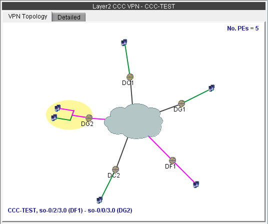
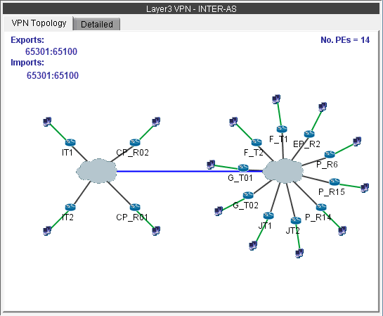
Figure 1: VPN View for a L2CCC VPN (with the selected circuit highlighted in pink)Layer 2 CCC VPN topology diagram with devices D01, DG1, DG2, DC1, DC2 connected via a cloud. Connection details shown: CCC-TEST so-0/2/3.0 DF1 - so-0/0/3.0 DG2. Five Provider Edges noted.
Figure 2: VPN View for an Inter-AS VPN (called INTER-AS)Network topology diagram for a Layer 3 VPN with Inter-AS configuration showing routers in two AS domains, key BGP route targets 65301:65100, and 14 PEs.

You may also display additional information (i.e., RD, Route Targets, interface) for a node by clicking on it for a pop-up window to appear, as shown in the following figure.
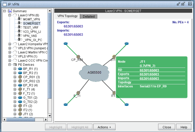
Figure 3: Green pop-up information window for a nodeScreenshot of network management interface showing Layer 3 VPN SOMERSET configuration with central node AS65500 and connected nodes CP_R01, EP_R11, IT1, JT1 with green lines indicating connections. Detailed info on node JT1 includes RD 65301:65003, Exports, Imports, and Interface Serial2/1 to EP_R9.

There is also a right-click menu that you can use to perform basic functions to manipulate the topology and the labels.
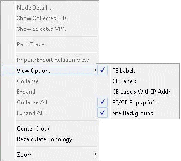
Figure 4: Right-click menu showing topology and label functionsContext menu for network topology management with options like Node Detail, Show Selected VPN, Path Trace, Import/Export, and View Options.