Viewing VLAN Topology
VLAN Topology View
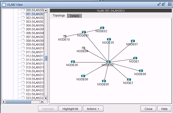
The VLAN topology view (or VLAN View) presents to the user a clear, logical view of each individual VLAN.To display logical topology view of any particular VLAN, simply click on the VLAN Topology tab (next to the Details tab). You may also move the nodes around as desired in the VLAN topology view map.
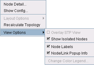
There is also a right-click menu that you can use to perform basic functions to manipulate the topology and the labels. Place the cursor on a node and do a right click to view node access and topology display options.
Spanning Tree Topology View
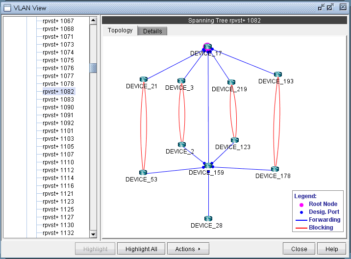
The topology of each spanning tree can be viewed on VLAN View window and also on the topology map with color coded links and nodes that identify root/designated nodes and port states.To view the topology on VLAN View window, click on a spanning tree on the left panel and open Topology tab.The legends at the bottom right corner explain the color codes.
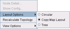
There is also right click menu that allows you to change the spanning tree topology layout into either tree or circular shape from the original MAP (standard) standard. Place the cursor on any point inside the topology window and do a right click to change the topology layout.
The Spanning tree topology can also be viewed on the topology map. Choose Subviews > L2STP from the top left drop-down menu on the Map (Standard) window.You should now view a list of all spanning trees present in the existing network with the following naming conventions: VLANID (Root Node) for PVSTs and STP-Type (Root Node) for all other types of spanning trees. Click on a spanning tree on the left panel to view its topology on the map. The nodes and links of the selected spanning tree are colored such that each color signifies their roles.
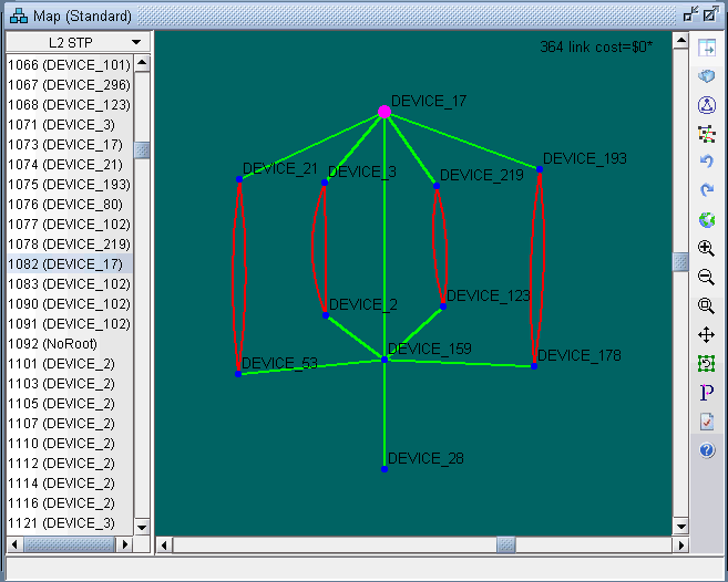
Following is a list of coloring conventions followed:
Pink Colored Node : Root Node.
Blue Colored Node : Designated Node.
Green Colored Node : Non-STP Node.
Green Colored Link : Ports on both ends of the link are in forwarding state.
Red Colored Link : Ports on one or both ends of the link are in blocking state.
