VLAN Modification and Design
Defining an Access Domain
An access domain is a group of physically connected layer2 devices that use spanning tree or direct connection to perform layer2 routing within the domain. Each access domain supports 4096 VLANs, thus allowing identical VLANs across multiple access domains. As direct physical connectivity information cannot be extracted from the config files, NorthStar Planner treats all the VLANs and STPs in the network as part of a default domain. The user should define access domains and assign the nodes to access domains to view VLAN and STP information categorized by access domains in VLAN View window.
To define an access domain, navigate to the Access Domains tab in the Network Info table. Click Add.
Enter Access Domain ID & Name details and choose spanning tree running across the access domain from the Spanning Tree Type drop-down menu in the top panel as shown in the following figure.
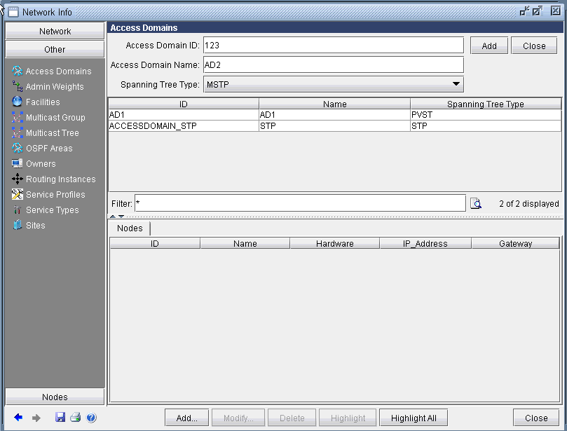
Click the Add button on the top right panel.The middle panel displays the list of all defined access domains and the newly added access domain should now add to the list.
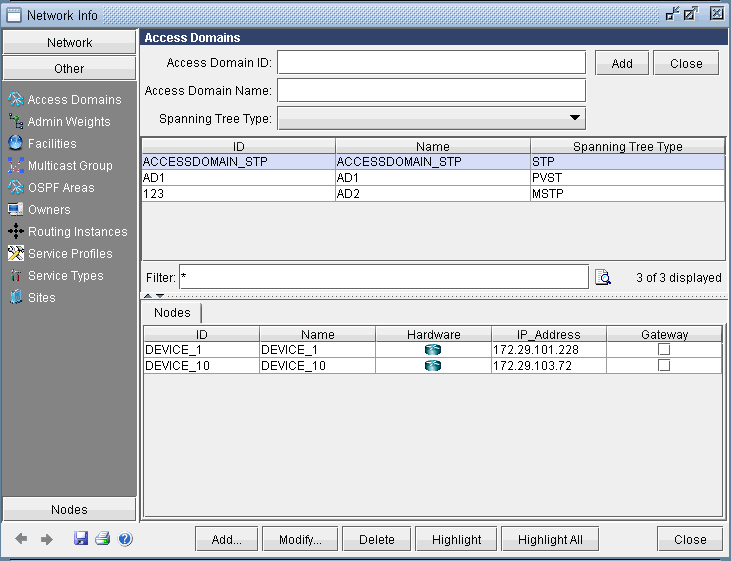
To view the nodes information of a particular access domain, click on an access domain in the middle panel and the bottom panel displays the information as shown in the following figure.
Modifying an Access Domain
To modify an existing access domain, click on an access domain in the middle panel, modify the access domain parameters and click Modify.
Deleting an Access Domain
To delete an access domain, click on an access domain in the middle panel and hit Delete. To only view the list of existing access domains and nodes details, click Close on the top right panel.
After adding all access domains, click Close at the bottom of Network Info window.
Assigning Nodes to Access Domain
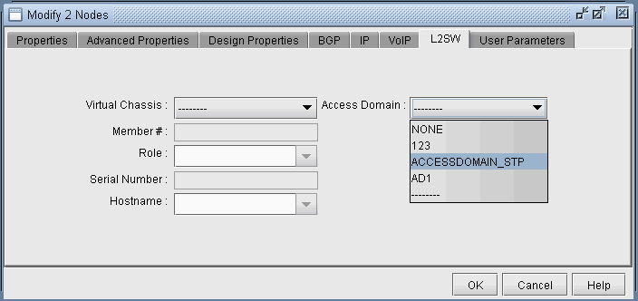
To assign nodes to an access domain, choose Network > Elements > Nodes...
Select a node/ multiple nodes that are located in an access domain and click Modify.
In the Modify Nodes window, select L2SW tab. Note that the L2SW tab is only available when a node is a layer 2 device (Properties tab > L2SW is true). Choose the access domain that the selected nodes belong to from the Access Domain drop-down menu, that lists access domain IDs, and hit OK. This completes the assignment of nodes to access domain.
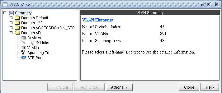
Below is a VLAN View window after adding access domains.
Adding Layer2 Links
To add Layer 2 links between switches, choose Modify > Services > VLAN.
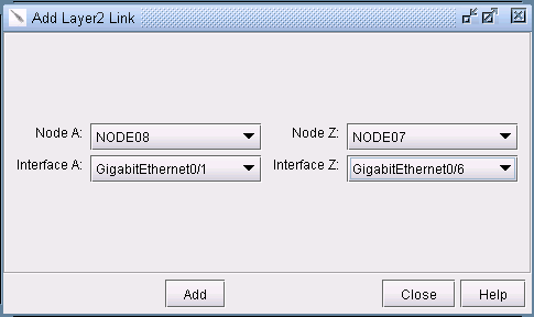
Click on the Layer2 Links sub-tree under the access domain and then click on the Add button form the VLAN View window.
Select two switches and the corresponding interfaces for the new link, and click on the Add button s shown in the following figure.
Adding VLAN Design and Modeling using VLAN Wizard
Besides the ability to derive the VLANs via network configuration import, the VLAN Module allows the network planner to construct and model a VLAN from scratch, and to modify or add to existing VLANs. The procedures described below on how to add VLANs also apply for modifying existing VLANs. Navigate to the VLAN tab on the Network Info tab.
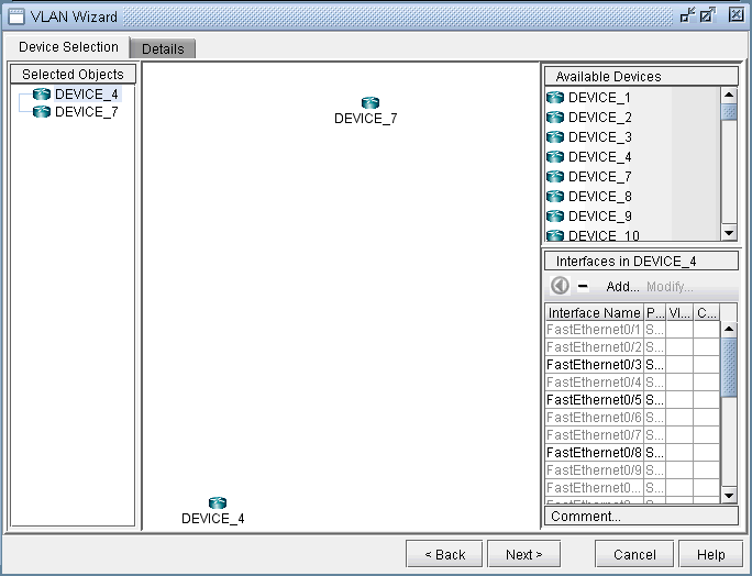
To add any VLAN in an access domain, click on the VLAN sub-tree under the Access Domain tab and then click on the Add button from the VLAN View window. To modify a VLAN, first select a particular VLAN and then click on the Modify button. When you click on Add, the VLAN Wizard window, shown in the following figure, is launched.
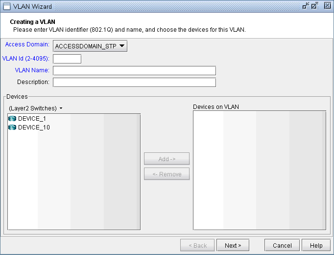
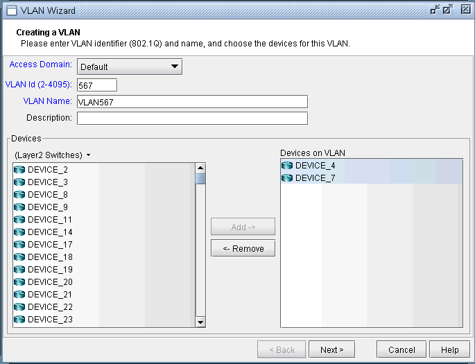
By default, the VLAN Wizard sets the access domain to the one you selected in the VLAN View window. You may choose a different domain from the Access Domain drop-down menu and then enter the VLAN details in the respective fields.In order to accommodate for multivendor non-management VLAN IDs, VLAN Wizard supports IDs above 2.
The Devices panel lists Layer2 Switches that belong to the selected Access domain. There is a drop-down menu under Devices (down arrow besides Layer2 Switches) from which you can select the device types you want to view and then add to Devices on VLANs. Choose the device type from the drop-down and use Add button to add the selected devices in Devices to Devices on VLANs panel. VLAN wizard adds the VLAN to the devices in Devices on VLANs.
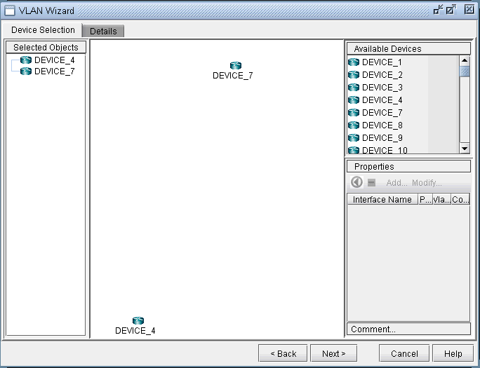
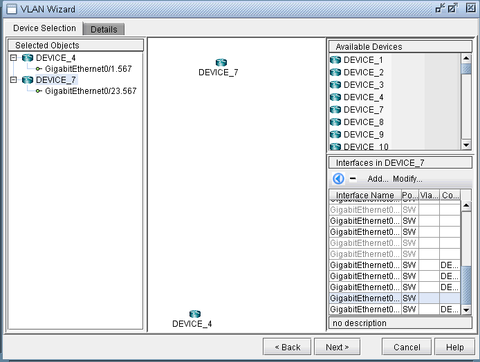
Click on Next to bring up the following window where you may add more devices and chosen devices interfaces to assign to the VLAN.
-
The middle part of the window show the topology area, where selected devices are placed.
-
The Selected Objects area, as the name implies, lists those devices that have been selected as VLAN devices.
-
The Available Devices box lists those routers for the currently chosen access domain.
-
The Properties box lists all the interfaces for a particular device when it is highlighted (a device is highlighted when it is clicked on either from the Available Devices list, the topology area of the window, or from the Selected Objects list)
The window is designed to be as user-friendly as possible, with drag/drop capabilities built in. The following figure shows the two devices that we have already added in the previous step.
In more detail, you may add additional devices to the VLAN from the Available Devices box via one of two methods:
Select one or more devices (at which point the icon that has the left arrow with a circle around it will change color from gray to blue), and then click on the blue arrow/circle icon to move it to the topology area part of the window (middle of the window).
Alternatively, you could simply drag and drop devices from the Available Devices list into the topology area of the window.
To assign interfaces to the selected devices, first select a particular device in order to have all its interfaces shown in the Properties box. A device is selected when it is clicked on from the Selected Objects list or from the topology area of the map. As shown in the following figure, the Properties box is now renamed as Interfaces in AD101, since the device AD101 has been selected. Another icon worth mentioning is the "-"/"+" button next to the arrow/circle button. Click on it to switch between "-" and "+". "-" means to show all interfaces, while "+" means to only display interfaces that are unassigned or not shutdown.
To assign an interface, you need to drag and drop a particular interface over to the device in the middle panel. Alternatively, you can select the device from the left hand side, and then select an interface from the interface list on the bottom right hand side, and click the blue arrow in the Interfaces section. The following figure shows the window after the interfaces have been assigned to the devices.
Note also the Add and Modify buttons in the Interface section. This can be used to add an additional interface, e.g., if you need to add a new subinterface, or to modify an existing interface.
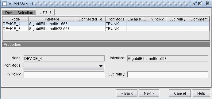
Click on the Details tab to assign in/out policies and port modes and then click Next. An interface’s port mode decides if multiple VLANs can be defined on it. An interface with the port mode set to ACCESS can belong to only one VLAN, while an interface with port mode set to TRUNK can belong to multiple VLANs. In general, the interfaces that are facing the customer are set to access modes.
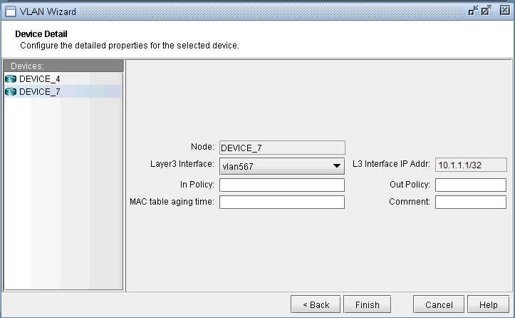
The details entered in the final VLAN wizard window facilitates for layer3 inter-VLAN routing. Click on a node in the left panel and choose a vlan interface from Layer3 Interface drop-down menu.
Layer3 interfaces are NorthStar Planner interfaces that should be created by the user to populate layer3 details in VLAN Wizard window. The procedure to create a vlan interface is similar to that of adding any new interface, either from Modify > Elements > Interfaces or from the Add button in the VLAN wizard window. Only rule is to begin the interface name with the keyword ‘vlan’ followed by VLAN ID.
IP address and in/out policies defined on the selected vlan interface will now be populated in the respective fields. L3 Interface IP Addr. field is used as node identifier while routing packets between VLANS with the applied in/out policies.
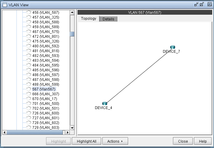
Click on Finish and you should now view the newly added VLAN to the VLANs sub-tree in the VLAN View window. The link between the two nodes signifies a direct physical connection between them. Click on the link to view the link details.
File Format
The following are special parameters in the dparam file related to VLANs.
-
keepl2stptree=1 : Setting this value to 1 will keep the spanning tree information parsed from the file. Setting this value to 0 will cause the program to be in a “smart” mode. For example, for isolated sections of a spanning tree without a root node, a root node will be selected.
-
addroot2treename=1 : When setting this value to 1, the spanning tree name in the VLAN view will be followed by the suffix @rootname to indicate the root node of the tree. If one tree is shown as multiple components in the VLAN window’s spanning tree view, this is an indication of missing links.
The following are special parameters in the specification file related to VLANs.
-
accdomain=filename : This file stores the region information for MST trees and is used to group trees by region in the VLAN window’s spanning tree view. This file can be commented out in the specification file by preceding the line in the specification file with a “#”.