ON THIS PAGE
Topology View Left Pane Options
The left pane drop-down menu offers several ways to filter the data that is displayed in the NorthStar Planner topology map pane. When you first open a network and display the topology, the initial view shows Protocols. Table 1 summarizes the left pane drop-down menu choices.
Option |
Description |
|---|---|
Protocols |
Lists protocols you can opt to display or hide on the topology map. Nodes configured with selected protocols are displayed. Selecting Default is the same as selecting all the protocols in the network. Click the check boxes corresponding to the protocols you want to select or deselect. |
Types |
Lists node types you can opt to display or hide on the topology map. Click the check boxes corresponding to the types you want to select or deselect. |
AS |
Selects autonomous systems (ASs) you can opt to display or hide on the topology map. Click the check boxes corresponding to the ASs you want to select or deselect. |
ISIS Areas |
Selects ISIS areas you can opt to display or hide on the topology map. Click the check boxes corresponding to the ISIS areas you want to select or deselect. |
OSPF Areas |
Selects OSPF areas you can opt to display or hide on the topology map. Click the check boxes corresponding to the OSPF areas you want to select or deselect. |
Node/Groups |
Displays user-created groups with or without listing the member nodes. Expanded groups are represented on the topology map by individual node icons. Collapsed groups are represented on the topology map by group icons, and the individual member nodes are not displayed. All nodes start out as ungrouped. |
The following sections describe the left pane display options:
Protocols
The Protocols list includes all protocols present in the current topology. Figure 1 shows an example.
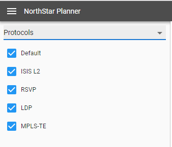
Protocols can be selected or deselected by checking or clearing the corresponding check boxes. Only network elements that support selected protocols are displayed in the topology map.
Select Default to display all protocols on the topology map. If you do not want elements supporting all protocols to be displayed on the topology map, be sure to clear the Default check box.
Types
The Types list in the left pane of the Topology view includes categories of nodes and links found in the network. Figure 2 shows a sample Types list.

Different types are associated with different icons, which are reflected in the topology map. You can select or deselect a type by checking or clearing the corresponding check box. Only selected options are displayed in the topology map.
All nodes of one type use the same icon.
AS
The autonomous systems (AS) list assigns a color, for purposes of representation on the topology map, for each AS number configured in the network. As noted in Figure 3, routers configured with AS 65536 would appear on the topology map as red dots. NONE shows the color assigned to routers with no AS configured.
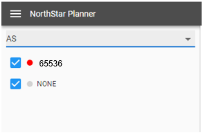
Select or deselect AS numbers by checking or clearing the corresponding check boxes. Only selected AS numbers are displayed in the topology map.
ISIS Areas
The ISIS Areas list assigns a color, for purposes of representation on the topology map, for each IS-IS area identifier configured in the network. The area identifier is the first three bytes of the ISO network entity title (NET) address. As noted in Figure 4, routers whose NET addresses include area identifier 11.0007 appear on the topology map as red dots. Those with area identifier 49.0011 appear as green dots. NONE shows the color assigned to routers with no NET address configured.
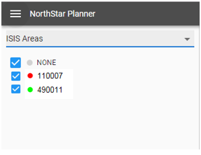
Select or deselect ISIS area identifiers by checking or clearing the corresponding check boxes. Only selected area identifiers are displayed in the topology map.
OSPF Areas
The OSPF Areas list assigns a color, for purposes of representation on the topology map, for each OSPF area configured in the network. NONE shows the color assigned to routers with no OSPF area configured.
As noted in Figure 5, routers with OSPF area 0 configured appear on the topology map as red dots. Those with OSPF area 1 appear as green dots. NONE shows the color assigned to routers with no OSPF area configured.
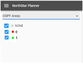
Select or deselect OSPF areas by checking or clearing the corresponding check boxes. Only selected areas are displayed in the topology map.
Node/Groups
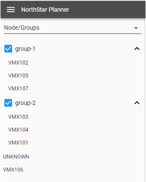
You can create groups of nodes by selecting nodes and using the right-click topology map functions. Nodes can also be auto-grouped using criteria that you provide. Once you have groups in your topology, the Node/Groups list in the left pane of the Topology view shows all your node groups, and lists all nodes not included in any group.
When you expand a group listing using the down arrow next to the group name, all the member nodes are listed. When you collapse a group listing using the up arrow next to the group name, only the group name appears in the list. In Figure 6, group-1 and group-2 are expanded. The nodes listed below group-2 are ungrouped.
The topology map reflects the expansion and collapse of the groups in the groups list. For an expanded group, all individual nodes are displayed in the topology map, without indication of which group they belong to. For a collapsed group, the individual node icons are collectively represented by a group icon. Hover over or click on the group icon in the map to display the group name.